Page is loading ...

Section 1:
Introduction
Welcome to the world of STAR TRAC. In your hands is the STAR TRAC TR 4500 Service Manual.
This manual is designed to be easy to use, providing detailed instructions on how to service and maintain
the TR 4500.
We highly recommend that you read all the applicable sections of the service manual prior to serving the
treadmill. The information on the following pages will enable you to begin easily, quickly, and safely.
Contents
1.1 How to use the Service Manual
1.2 Precautions
1.3 Product Support Assistance
1.0
1.4 Tools and Test Equipment
1.5 Treadmill Overview.

How To Use This Manual
• This Service Manual has been written to assist and instruct the repair technician on key
components for quick and efficient diagnosis of service problems.
• To assist in finding the applicable sections in the Service Manual. Each Section has a table of
contents to help locate specific symptoms and topics. Titles and major headings are located at the
top of every page.
• This manual is to be used strictly as a Maintenance manual for service and repair, not as an
owner’s manual.
• An illustrated Parts List is located at the back of this manual for identifying parts with part
numbers.
• Troubleshooting tables and Error Code Flowcharts are included for certain sections to help
diagnose the system problem and find the root cause.
1.1

Precautions
1. Always make sure that the treadmill is turned off and unplugged before starting any work, unless
otherwise noted, or when necessary for voltage testing.
2. Read each section through for NOTES before starting any work.
3. To pull apart electrical connectors, pull on the connector itself, not the wires.
4. When replacing fuses, be sure the new fuses is the correct amperage rating. Do Not exceed the
fuse amp rating. If necessary use a fuse of lower rating until the proper fuse may be attained.
5. When checking continuity at the wire connector, insert the test probe carefully to prevent the
terminals from bending.
1.2

Product Support Asistance
PRODUCT SUPPORT DEPARTMENT
STAR TRAC Product Support Department sets the industry standard in Customer Service and
Technical Assistance World Wide. Providing superior product support and customer service is at the
very heart of STAR TRAC’s business philosophy. This commitment to service has been a major
contributor to STAR TRAC’s success and growth in the worldwide fitness equipment industry.
Technical Assistance
• When purchasing a part or requesting technical assistance, please contact our Product Support
Department : CALL TOLL-FREE: 1-800-535-4634 or 800-503-1221 US and CANADA or
714-669-1660
• When placing the call, please have the following information available:
1. STAR TRAC model.
2. STAR TRAC serial number
3. Problem statement / symptom.
After Hours Voicemail Direct
• CALL TOLL-FREE: 1-800-486-4736
• When placing the call, please have the following information available:
1. STAR TRAC model.
2. STAR TRAC serial number
3. Problem statement / symptom.
4. Return phone number and contact name.
Fax Requests
• Domestic and International: Fax 714-669-0739
• When placing the fax, please supply the following information:
1. STAR TRAC model.
2. STAR TRAC serial number
3. Problem statement / symptom.
4. Return phone fax number and contact name.
5. Purchase order or reference number.
6. Part description and quantity.
7. Ship to/bill to.
Product Support Documentation Access
• Web page http://www.startrac.com/support/
• Docufacts CALL TOLL FREE 1-800-429-3228 ext. 640 US and Canada or 714-253-3878 for a list
Product Support Procedures and Bulletins.
1.3

Tools and Equipment
Equipment Function
Philips Head Screwdriver #2 Shroud
Motor Control Board Assembly
Side Bed Cover and End Caps
Auto-Transformer
Small Slotted Screwdriver 3/32” Motor Control Potentiometers (MAX SPD) & (IRCOMP)
Bungee Cord 28” Suspend Motor Shroud on Display Rail
5/32” Hex Allen key Handrail assembly
5/64” Hex Allen key Display Board set screws
1/8” Hex Allen key Display Assembly
1/4” Hex Allen key Running Belt
Head Roller
Tail Roller
5/16” Wrench or Nut Driver Drive Motor Bolts
9/64” Allen Wrench Elevation Motor
17-mm Socket Wrench
Multi-meter Voltage Checks
Continuity / OHM ΩChecks
1.4

Treadmill Overview
• DC POWER SUPPLY
The MCB provides power to the display assembly. Establishes a reference voltage
and potentiameter position from the elevation motor
• RUNNING BELT MOTOR DRIVE CONTROL
Takes Alternating Current and converts it to Pulse Width Modulation
(PWM) to power the Drive Motor.
Motor voltage feedback and control-speed-commands determine the level
of PWM power delivered to the motor.
Motor Control circuits include fault sensing and safety functions.
• TACHOMETER SIGNAL CONDITIONING
The signal from the RPM sensor is fed to signal conditioning circuits on the MCB, where the signal is
converted to a digital output that is utilized by the Display Assembly to indicate belt speed.
• ELEVATION MOTOR CONTROL
The elevation circuit on the MCB receives elevation direction and enable
information from the Display Assembly, using these signals to provide
control to the Elevation Motor. Elevation position information, in turn, is
fed to the Display Assembly to indicate percent of incline.
1.5

Section 2:
Preventive Maintenance
Schedules
Performing regular preventive maintenance on all Star Trac treadmills is strongly recommended. Without
preventive maintenance, normal wear and tear may cause cumulative effects, such as misalignment and
early replacement of parts. This may result in downtime. For this reason, we highly recommend following
the manufacturer’s maintenance schedules.
Contents:
2.1 Preventative Maintenace Chart
2.2 Waxing Procedure
2.0

Preventive Maintenance Chart
Maintenance Clean Inspect Lubricate Replace
Daily
Using a liquid
non-abrasive
cleaner, wipe
down the
following:
display board
handrails,
shroud, heart
rate grips.
Note: Do not
spray directly
onto the
display
board or heart
grips.
Inspect for wear
and tear on ex-
terior parts
regularly,
especially under
the running belt.
Inspect the line-
cord plug and
cord for possible
damage or loose
connection.
Weekly
Elevate the
treadmill and
vacuum under
the unit.
Note: Unplug
the unit when
vacuuming.
Verify running
belt alignment
and tension.
Inspect the area
under the
treadmill for
obstructions.
Monthly
Lift the motor
shroud and
vacuum
around the
motor and
electronics.
Clean and lub-
ricate the elev-
tion screws.
Note: This
must be done
with the unit
unplugged and
turned off.
Inspect the
display and
handrail screws
for loosening.
Inspect the
display panel
keys for wear.
Using a silicone
spray lubricate
the elevation
screws, while
the unit is
elevated.
Note: This must
be done with the
unit
unplugged and
turned off.
Quarterly
Wax the running
belt and deck
using Unisen
powder wax.
2.1

Quarterly Waxing
The treadmill is designed with an automatic prompt, which will display RE WAX
across the display screen every 2,000 miles or 3,000 kilometers. The procedure
below explains step-by- step how to apply wax and clear the RE WAX prompt.
Note: Apply wax
powder while
belt and deck are
still warm (from 5
to 15 minutes of
use) for optimum
benefit. The foll-
owing steps are
done with the
treadmill off.
Time Required:
5 minutes
Tools Required:
1 Wax Powder Bag (Unisen)
Teaspoon
1 Clean Towel
Paint Stick or Yard Stick
Diluted All-purpose Cleaner (409)
Bristle Brush
Note: Blow away
extra wax first
from around the
siderails and
deck before wip-
ing.
Note: The RE
WAX prompt may
be cleared either
in “Settings or
Configure Mode”.
PROCEDURE
STEP 1: Cleaning the deck and belt:
• Using the stick or ruler, slide a towel under the middle of the running belt from
one side of the frame to the other.
• Hold the edges of the towel, pull from head-roller down to the tailroller, then pull
the belt down to wipe the remaining of the belt. TIP: Careful when removing the
towel, it will be dirty. Fold the dirty towel and shake into trash.
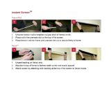
STEP 2: Re-waxing the deck and belt:
• Lift the left side (facing the display) of the belt, about 12 inches down from the
motor shroud (see above figure). Hold the belt up such that the width of the belt
is elevated from the deck.
• Gently place one level teaspoon of wax powder on the deck about two inches
from the edge, and blow the wax steadily under the belt, so that the wax powder
is spread evenly across the deck (see above figure). Gently place a second
level teaspoon of wax 18 inches down the belt.
• Repeat the above step to the right side of the belt and deck.
STEP 3: Walking the wax in:
• Start the treadmill at 1 mph and walk on all sections of the belt and deck for 1
minute to ensure the wax has been evenly distributed and worked-in properly.
STEP 4: Clean-up:
• Remove any excess wax with diluted cleaner (409) and towel, or bristle brush.
STEP 5: Clear RE WAX prompt:
• Engage Settings or Configure Modes. Press and hold the “0”, “1” or(2) &
“START” keys down, release the “1” or (2) key only. Display will beep and
display SETTINGS or CONFIGURE momentarily (depending if the 1 or 2 key
was released), then UNITS will be displayed.
• Press the Incline Down Key (elevation) until LSTDCK is displayed. Press and
release the HEART Key, this will automatically transfer the accumulated
miles/kilometers into the LSTDCK, press the ENTER Key to save.
2.2

Section 3:
Diagnostics
The STAR TRAC 4500 Treadmill series contains diagnostic and customizing modes. In these modes
you are able to check accumulated data about the past usage of the treadmill, test its motor and
display controls, and investigate display code messages. For these reasons, your treadmill is equipped
with a ;
• Manager Mode (customize)
• Maintenance Mode (diagnostics)
• Motor Test Mode (diagnostics)
• Display Test Mode (diagnostics)
• Heart Rate Test Mode (diagnostics)
Contents:
3.1 Engaging Manager Mode
3.2 Engaging Maintenance Mode
3.3 Description of parameters
3.8 Engaging Motor Test Mode
3.9 Calibration
3.10 Engaging Display Test Mode
Heart rate test
3.0

Manager Mode
After having used you Star Trac 4500 treadmill for several workouts, you may wish to specially
customize your treadmill by changing some of its settings.
To engage Manager Mode:
1. Press and hold the “ 0 ”, “ 1 ” & “ START ” keys together. While holding the “ 0 ” &
“ START ” keys down, release the “ 1 ” key only.
2. The display will beep and display Manager Mode momentarily, then UNITS will be displayed.
Once the treadmill is in Manager Mode, you may use the following keys:
INCLINE KEY: Displays the next or previous parameter.
SPEED KEYS: Allows the variable to be changed within the parameter.
ENTER KEY: Saves the value if changed in the EPROM (software).
Note: ENTER KEY must be pressed, for each value changed.
STOP KEY: Exists Manager Mode and restarts the treadmill with a “warm start.”
0 – 9 KEYS: Enters new parameter values. If UNITS parameter is displayed, key 5
starts DISPLAY TEST and key 8 starts MOTOR TEST.
HEART HEART KEY: When pressed will automatically display manufactures default value.
Note: ENTER KEY must be pressed, to save the default values if changed.
3.1

Manager Mode
The following parameters may be changed using the previous keys:
Parameters Lowest
Value
Highest
Value
Option 1 Option 2 Default
Value
Meaning
UNITS
--- --- English Metric English English= units of lbs.,
miles, hours, minutes
Metric= units of kg.,
km, hours, minutes.
MN SPD
0.1 2.5 English=0.5 Metric=1.0 0.5 Minimum speed in
MPH or KM/HR
MX SPD
5.0 20.0 English=10.0 Metric=20.0 10.0 Maximum speed in
MPH or KM/HR
EL OPT
--- --- ON OFF ON Turns the elevation
system ON or OFF.
TIME
5 99 99 Maximum time in
minutes allowed for
program, including
warm-up/cool-down.
OP HRS
0 0 --- --- 6,553.5 Total operating hours
DIST
0 0 --- --- 65,635 Total treadmill miles
(Units=English)
or kilometers
(Units=Metric)
WEIGHT
0 399 --- --- 155 Defaults (to user),
typical weight in lbs/kg
depending on what
setting (UNITS=
English or Metric
SER NO
0 0 --- --- 65,535 Treadmill serial
number.
LANG
--- --- --- --- English Language in English,
Dutch, German,
Portuguese, Spanish,
Swedish, or Italian.
ENTRY
--- --- Units Tenths Units This variable changes
the starting speed in
Units or Tenths
3.2

Maintenance Mode
Maintenance Mode includes all of the items of Manager Mode, plus additional data that is automatically
saved to properly troubleshoot in case of a problem. To engage Maintenance Mode:
1. Press and hold the “ 0 ”, “ 2 ” & “ START ” keys together. While holding the “ 0 ” &
“ START ” keys down, release the “ 2 ” key only.
2. The display will beep and display MAINTENANCE momentarily, then UNITS will be displayed.
Once the treadmill is in Maintenance Mode, you may use the following keys:
INCLINE KEY: Displays the next or previous parameter.
SPEED KEYS: Allows the variable to be changed within the parameter.
ENTER KEY: Saves the value if changed in the EPROM (software).
Note: ENTER KEY must be pressed, for each value changed.
STOP KEY: Exists Manager Mode and restarts the treadmill with a “warm start.”
0 – 9 KEYS: Enters new parameter values. If UNITS parameter is displayed, key 5
starts DISPLAY TEST and key 8 starts MOTOR TEST.
HEART HEART KEY: When pressed will automatically display manufactures default value.
Note: ENTER KEY must be pressed, to save the default values if changed.
3.3

Maintenance Mode
The following parameters may be changed using the previous keys:
Parameters Lowest
Value
Highest
Value
Option 1 Option 2 Default
Value
Meaning
UNITS
--- --- English Metric English English= units of lbs.,
miles, hours, minutes
Metric= units of kg.,
km, hours, minutes.
MN SPD
0.1 2.5 English=0.5 Metric=1.0 0.5 Minimum speed in
MPH or KM/HR
MX SPD
5.0 20.0 English=10.0 Metric=20.0 10.0 Maximum speed in
MPH or KM/HR
EL OPT
--- --- ON OFF ON Turns the elevation
system ON or OFF.
TIME
5 99 99 Maximum time in
minutes allowed for
program, including
warm-up/cool-down.
OP HRS
0 0 --- --- 0 Total operating hours
DIST
0 0 --- --- 0 Total treadmill miles
(Units=English)
or kilometers
(Units=Metric)
WEIGHT
0 399 --- --- 155 Defaults (to user),
typical weight in lbs/kg
depending on what
setting (UNITS=
English or Metric
SER NO
0 0 --- --- 0 Treadmill serial
number.
LANG
--- --- --- --- English Language in English,
Dutch, German,
Portuguese, Spanish,
Swedish, or Italian.
ENTRY
--- --- Units Tenths Units This variable changes
the starting speed in
Units or Tenths
3.4

Maintenance Mode
Parameters Lowest
Value
Highest
Value
Option 1 Option 2 Default
Value
Meaning
HRT CON
--- --- ON OFF OFF OFF= Heart Control
disable
ON= Heart Control
enabled
HRT
--- --- CNT DN
POLAR
CONTACT
BOTH
CNT DN
POLAR
CONTACT
BOTH
CNT DN CNT DN= Manual
countdown heart rate
POLAR, CONTACT or
BOTH (Polar &
Contact)
10 REV
22.0 74.0 30.7 = For
110v units.
35.8 = For
220v units
29.1 Inches of running belt
travel for 10 flywheel
revolutions, measured
in inches.
1.8” pulley:30.7 (110v)
2.1”pulley:35.8(220v)
CNT/REV
1 255 31 =
Magnetic
RPM Sensor
125 =
Optical
Sensor
31 Number of counts per
RPM Sensor
revolution.
MN PWM
2 50 --- --- 30 Minimum PWM to
obtain minimum
speed, automatically
done.
1/2 PWM
25 170 --- --- 130 1/2 Maximum PWM to
obtain 1/2 maximum
speed, automatically
done.
MX PWM
86 255 --- --- 230 Maximum PWM to
obtain maximum
speed, automatically
done.
DATE
1.00 12.99 --- --- 1.96 Treadmill
manufacturing date.
NO STO
0 255 --- --- 0 Number of times the
Stop Switch was down
or disconnected on
power-up since last
reset.
3.5

Maintenance Mode
Parameters Lowest
Value
Highest
Value
Option 1 Option 2 Default
Value
Meaning
KEY DN
0 255 --- --- 0 Number of times the
Stop Switch was down
or disconnected on
power-up since last
reset.
NO RPM
0 255 --- --- 0 Number of times the
display did not detect
a RMP signal.
SP CNG
0 255 --- --- 0 Number of times a
sudden change in
speed was detected
EL STL
0 255 --- --- 0 Number of times an
elevation stall was
detected.
EL RNG
0 255 --- --- 0 Number of counts per
RPM Sensor
revolution.
EL LOST
0 255 --- --- 0 Number of times no
elevation was
detected.
ELZERO
0 255 --- --- 240 Represents the incline
number for 0%.
EL MAX
0 255 --- --- 57 Represents the incline
number for 15%.
LSTERR
0 25 --- --- 0 Indicates what display
code appeared last.
18 = NO STO
19 = KEYDN
20 = NO RPM
21 = SP CNG
22 = EL STL
23 = EL RNG
24 = EL LOST
LSTELV
0 255 --- --- 0 Displays the target
elevation prior to the
display code.
LSTPOT
0 255 --- --- 0 Displays the incline
number prior to the
display code.
3.6

Maintenance Mode
Parameters Lowest
Value
Highest
Value
Option 1 Option 2 Default
Value
Meaning
LSTRES
0 2 --- --- 0 Displays
1 = Unit was resetting
to 0%.
0 = Unit finished
resetting to 0% prior
to the display code.
LSTSSP
0 255 --- --- 0 Displays the speed
prior to the display
code.
LSTPWM
0 255 --- --- 0 Displays the PWM
number prior to the
display code.
LSTMSP
0 255 --- --- 0 Display the actual
measured speed prior
to the display code.
LST TM
0 65355 --- --- 0 Displays the elapsed
time, in seconds, prior
to the display code.
LSTDCK
0 65355 --- --- 0 Number of miles when
the deck was last
waxed. After a 2000
mile (or 3000 KM)
difference, “REWAX
BELT” will scroll in the
display until “LST
DCK” miles are
updated.
LSTBLT
0 65355 --- --- --- Number of miles when
the last belt was
replaced.
3.7

Motor Test Mode
Motor Test Mode allows the treadmill to calibrate both elevation and running belt speed. Verifies RPM
Sensor feedback, Drive Motor and MCB response, and verifies Elevation Motor range (count). Also
burns in the motor, by way of the controls and displays of the treadmill.
***Caution*** : Do not stand on the running belt while performing these test.
Engage Test Mode:
1. Press and hold the “ 0 ”, “ 1 ” & “ START ” keys together (or the “0” , “2” ). While holding the “ 0 ”
& “ START ” keys down, release the “ 1 ” (or 2) key only. The display will beep and display
MANAGER (or MAINTENANCE) momentarily, then UNITS will be displayed.
2. Press and release the “8” key. Display will read: 240 3 .0 if treadmill is at 0%.
Alternative mode to enter Motor Test Mode:
1. Turn the power switch on while pressing the “ 8” key simultaneously on the display.
240 3 .0
A. Elevation Motor Range. B. PWM Duty Cycle. C. RPM Sensor Feedback
Once the treadmill is in TEST Mode, you may use the following keys:
INCLINE KEY: Adjust voltage to incline motor, inclines the treadmill in increments of 1%.
When using the Incline Keys verify the elevation system is responding correctly by the
following:
• As the treadmill elevates up and down verify the corresponding LEDs light up on the MCB.
• Verify that the Elevation Motor Range (see above A column) is changing in increments of
1% as the treadmill elevates up and down.
Caution:Do not elevate treadmill above 15% = 57 (110v units), 80 (220v units) or below
0% = 240 (110 & 220v units) mechanical damage may occur.
SPEED KEYS: Adjust the PWM duty cycle and motor speed up and down, respectively,
in increments of 0.1 mph (UNITS=English) or 0.1km/hr (UNITS = Metric).
When using the Speed Keys verify the speed control system is responding correctly by the
the following:
• As the treadmill begins to increase speed, verify that the display registers RPM feedback
(see above C column) in increments of 0.1 mph/km.
START KEY: Starts burn-in mode. (continuous operation of running belt and incline using
program 8 at maximum speed. Press STOP KEY to stop burn-in.
STOP KEY: Exists MOTOR TEST Mode and restarts the treadmill.
HEART KEY: Starts automatic calibration of minimum, 1/2 maximum, & maximum speed.
3.8

Calibration
***Caution*** : Do not stand on the running belt while performing these test.
Automatic Speed Calibration:
In this mode minimum and maximum speed is automatically calibrated. Calibration lasts less than 3
minutes; belt will be in motion during this test.
Auto-calibration should be done every time MN, MX SPD & UNITS parameters have been changed in
either SETTINGS or CONFIGURE Mode. Auto-calibration must be engaged when ever speed
controlling components have been upgraded or replaced such as; MCB, Display Board, Drive Motor &
RPM Sensor.
1. Press and hold the “ 0 ”, “ 1 ” & “ START ” keys together (or the “0” , “2” ). While holding the “ 0 ”
& “ START ” keys down, release the “ 1 ” (or 2) key. The display will beep and display MANAGER
(or MAINTENANCE) momentarily, then UNITS will be displayed.
2. Press and release the “8” key. Display will read: XXX 3 .0 if treadmill is at 0% display will read:
240 3 .0
3. Press “HEART” key, display will read: CAL treadmill will go into an automatic speed calibration for
less than 3 minutes. Press “STOP” key to exit Motor Test.
NOTE: If Auto-calibration fails to give the correct response refer to Section 4.
3.9

Display Test Mode
Display Test Mode allows you to test the light-emitting diodes (LEDs), 15-segment displays, and the
watchdog timer of the Display Control Panel by way of its own controls and displays. It also allows
EPROM version to be displayed. To enter Display Test Mode:
***Caution*** : Do not stand on the running belt while performing these test.
1. Press and hold the “ 0 ”, “ 1 ” & “ START ” keys together (or the “0” , “2” ). While holding the “ 0 ”
& “ START ” keys down, release the “ 1 ” (or 2) key.
2. The display will beep and display MANAGER (or MAINTENANCE) momentarily, then UNITS will
be
displayed.
3. Press and release the “5 key. Observe all the LEDs light up.
4. Pressing any key once will display the EPROM version.
Alternative mode to enter Motor Test Mode:
1. Turn the power switch on while pressing the “5” key simultaneously on the display. Observe all the
LEDs light up.
Once the treadmill is in Display Test Mode, you may use the following keys:
INCLINE KEYS: Lights % grade LED’s one at a time, also segments of 15-segment
screen one at a time.
PROGRAM SELECT KEY: Lights the six LEDs bordering the 15-segment display.
HEART KEY: Displays “HEART HEART” on the 15-segment display.
START KEY: Displays “START START” on the 15-segment display.
0 – 9 KEYS: Lights corresponding LEDs in the Number/Program Select Keys, (except
for key 9), alongside the Pre-Designed Program profiles.
STOP KEY: Displays “WD TEST” on the 15-segment display. Activates the watchdog
timer, resetting the processor and returning the program back to Start Mode.
3.10
/