
Dear User,
we are sincerely grateful to you for purchasing one of our products.
We are sure that the appliance modern, functional and easy to use, built with the finest materials
and components will satisfy all your needs.
We would ask that you read the instructions within this booklet very carefully so as to enable you
to obtain quality results from the outsets.
The appliance must be installed only by a qualified electrician in compliance with the
instructions provided. The manufacturer declines all responsability for improper installation.
USE, INSTALLATION AND MAINTENANCE
INSTRUCTIONS FOR ELECTRICAL
BUILT-IN HOT PLATES
The manufacturer is not responsible for any transcription errors or misprints contained in this handbook and,
furthermore, reserves the right to make any modification on the products, which might be deemed
necessary or usefull, this being in the user’s interest, without altering their basic operating or safety
features.
COD. 120116SMN1 (120116ING) - 26.10.2009
SMEG S.p.A.
Via Leonardo da Vinci, 4
42016 GUASTALLA - ITALIA
TYPE: PFVZ 02
MOD.: SE32CX

14
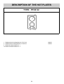
DESCRIPTION OF THE HOT PLATES
1 Radiant electric heating element Ø 145 mm 1200 W
2 Radiant electric heating element Ø 180 mm 1700 W
9 Switch for electric element n. 1
14 Switch for electric element n. 2
TYPE: PFVZ 02

15
USE
1) ELECTRIC HOB
The hot plates are equipped with radiant heating
elements with different powers and diameters.
Cooking zones are aesily identifiables thanks to the
circles (see illustration in description) on the top;
relative powers are listed in the scheme n.1.
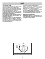
On the frontal panel, close to each knob, has been
silk-screened a scheme where is indicated to which
cooking zone the knob refers (fig. 1).
In some particular models the scheme annexes a
light indicator that turns on when the cooking zone
temperature is above 60° C.
The indicator will turn off only when the temperature
of the cooking zone will be below the value: this is
the reason why we call it residual heat indicator.
Some other models they have only one indicator
(see description paragraph).
Connection of electric heating elements
Heating elements are controlled by energy
regulators with 12 positions (fig. 1) that permit to
obtain a big range of different temperatures.
In Scheme 1, by way of information, we give
instructions to obtain different cooking levels.
To connect the heating elements is necessary to
turn clockwise or anticlockwise the relative knob.
How to use the cooking zones
Heating takes place only in the inside part of the
circles drawn on the special glass. The circles have
to be wholly covered by the pots.
FIG. 1

16
USE
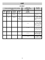
SCHEME 1
1 145 Radiant 1200 1
2 180 Radiant 1700 1 - 4
(1800 if
"Hilight")
8 - 10
4 - 8
Zone Diameter Heating Power Energy
n° in mm element W regulators
12
10 - 12
To heat foods,
thaw deep-frozen
foods, to cook
fruits and pulses.
To melt butter,
chocolate and
else.
To fry with oil and
to heat big
quantities of water.
To cook roast of
meat, fish; to cook
steaks and eggs.
To cook meat, fish,
pulses with sauce.
To heat small
quantities of liquid
and to keep dishes
warm.
Power and dimensions of the cooking
zones
Position for
regulation of the
knobs
Possible
cookings

17
USE
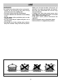
WARNINGS:
for a correct use, please look at fig. 2 and remind:
- Switch on the electricity only after having
placed the pot on the cooking zone.
- Use pots and pans with flat solid bottoms.
- Use pots with the same diameter of the cooking
zones.
- Dry the bottom of the pot before put in on the
cooking zones.
- Do not scrape the pot against the glass so to
not damage it.
- During the use of the cooking zones, please,
keep the children away from the hot plates.
Make sure that the handles of the pots are
placed in the right way towards the interior.
Be aware that overheated fats and oils may
become inflamed.
- Cooking zones after using remain warm; don’t
leave objects, don’t lean your hands so to avoid
burns, till the indicator light is off.
- If the glass cracks, please, disconnect the
appliance.
- Don’t use plastic pots or alluminium sheets.
- Don’t use hob as a supplementary surface.
FIG. 2

18
CLEANING
Before any cleaning operation, disconnect the
appliance from the electric circuit.
2) ELECTRIC HOB
If you want to preserve the surface clean and bright,
we recommend you to use a silicone conditioner.
The use of this conditioners, prior to jam-making,
helps to protect the surface of the hob.
It is very important to clean the surface soon after
every use, when the glass is still tepid.
Do not use metallic sponges, powder abrasives or
corrosive sprays.
Depending on the dirty level we recommend:
- slights stains: it is enought the use of a moist clean
rag.
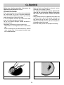
- Burnt or soiling may be removed with a special
razor scraper (fig. 3); be aware that the razor
can cause wounds.
- Marks of liquid, overflowed from the pot, can be
removed using vinegar or lemon.
- Pay attention to not let fall sugar or element with
sugar. In this case turn the switch off and clean
the surface with hot water and the razor blade
scraper.
- After a period of time may appear metal reflex and
scratches (fig. 4) due to the wrong cleaning and
the wrong use of the pots. The scratches are
difficultly removable, but they do not compromise
the good working of the hob.
- Don’t use steam jets for the equipment cleaning.
FIG. 3
FIG. 4

19
INSTALLATION
TECHNICAL INSTRUCTIONS FOR THE
INSTALLER
Installation, transformations and maintenances
below listed, may only be carried out by a
competent technician.
A wrong installation may provoke damages to
persons, animals or things, for which the builder
can not be responsible.
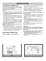
3) INSERTING
After having cleared out all the packing components,
make sure of the integrity of the appliance.
Please keep children away from all packing
elements ( carton, polystyrene, nails,..).
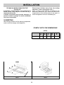
Make a cutout in the worktop, according to the
dimensions indicated in fig. 5; make sure that will be
respected the critical dimensions of the space in
which the appliance has to be installed (fig.6).
COMPLY WITH THE DIMENSIONS
(mm)
A B C D E
EL. HOB 30 282 482 59 59 100
min.
FIG. 5 FIG. 6

20
INSTALLATION
4) FIXING
A special sealing strip underneath the hob for
damage. Make sure it is correctly positioned with no
gaps; it avoids any water infiltration. To fix in the right
way the strip, please, respect the following
instructions:
- fix the hooks in the relative accomodations of the
body (see fig. 7).
- Overturn the hob, take the seal strips off from their
support, having care that the transparent protection
remains attached to the seal. Correctly place the
seal "E" (fig.7) under the hob edge, so that the
external side of the seal fits together with the
external perimentrical edge of the hob. The ends of
the strip must fit together without overlapping.
- Stick the seal to the hotplate uniformly, pressing it
with fingers.
- Take the protective paper strip of the seal off, place
the hotplate in the opening made in the table top,
and lock it with the special screws "F" (fig. 8).
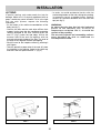
- In order to avoid accidental touch with the
overheating bottom of the hob, during the working,
is necessary to put a wooden insert, fixed by
screws, at a minimum distance of 60 mm from the
top (see fig. 5).
WARNINGS:
be aware that the glue that join the laminated
plastic to the furniture, has to resist to
temperature not below 150 °C, to avoid the
unstuck of the panelling.
The rear wall, adjacent and surrounding surfaces
must therefore be able to withstand an
overtemperature of 65K.
FIG. 7 FIG. 8

21
INSTALLATION
5) ELECTRICAL CONNECTION
The electrical connection has to be done in
accordance with all electrical and installation
requirements of the regulation.
Before proceeding with the connection, please,
verify that:
- the power of the electrical system and the power
of the outlets is adequate to the maximum power
of the appliance (see the identification label in the
lower part of the body).
- The outelets and all the electrical system has an
efficient connection to the "earth" according with
the Regulation. We disclaim all responsabilities
for not observing such points.
- If the appliance is not equipped with an input
cable, connect to the clump with an adequate
section cable (see scheme paragraph 7) keeping
the "earth" conductor longer than "live" ones,
following the scheme of fig. 9.
When the connection to the input system has
been done through a outlet:
- apply to the input cable "C", if unprovided, a
normalized plug adequate to the load indicated in
the identification label. Connect the cables
according to the scheme of fig. 9, making sure to
respect the undermentioned respondences:
Letter L (Live) = cable brown colour;
Letter N (Neutral) = cable blue colour;
Earth symbol = green - yellow wire.
- The input cable has to be located so that never
reach the over temperature of 75K.
- Please do not use in the connection any
reduction, adaptation that may provoke a false
contact with following dangerous overheatings.
- The outlet must be accessible after the built-in.
When the connection has been done directly to
the input system:
- interpose between the appliance and the system
an onnipolar switch, adequate to the load of the
appliance, with a minimum nose between the
contacts of 3 mm.
- Keep in mind that the " earth " cable does not
have to be interrupted by the switch.
- In an alternative solution the electrical connection
can also be protected by a differential switch with
high sensitivity.
We recommend to fix the earth coloured cable to
an appropriate earth installation.
WARNINGS:
all our products are projected and built
according with the European Norms
EN 60 335-1, EN 60 335-2-6 and relative
amendments.
Th e ap p li a n c e h a s b e e n p r o d u c e d
according with the European Directives:
- CE E 2 0 0 4 / 1 0 8 / C E c o n c e r n i n g th e
compatibility electromagnetic.
- CEE 2006/95 concerning the electrical
security.
FIG. 9
FIG. 10

22
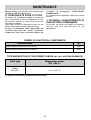
MAINTENANCE
Before doing any action, disconnect the
appliance from the input power.
6) COMPONENTS SUBSTITUTION
To replace the components lodged in the internal
part, is necessary to take the appliance up from
the furniture, overturn it, loosen the screws and
take away the bottom.
After these actions is possible to work on the
plates, commutators, clamps and input cable.
In case of substitution of the input cable, the
installer must keep the "earth" conductor
longer than "live" ones, and must respect the
cautions in paragraph "ELECTRICAL
CONNECTION".
To reassemble the appliance repeat the inverse
process.
7) TECHNICAL CHARACTERISTICS OF
THE ELECTRICAL COMPONENTS
To facilitate the job of the installer we present a
scheme with the characteristics of the
components.
Denominations W
Radiant electric heating element Ø 145 mm 1200
Radiant electric heating element Ø 180 mm 1700
POWER OF ELECTRICAL COMPONENTS
TYPE AND SECTION OF THE POWER CABLES (for 2 or 1 HEATING ELEMENTS)
(*) keeping in mind the contemporaneousness factor
3 X 1.5 mm
2
(*)
Cable type Single phase power
230 - 240 V ~
Rubber
H05 RR-F

23
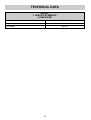
TECHNICAL DATA
MODEL
2 HEATING ELEMENTS
(2 RADIANTS)
Voltage 230 – 240 V ~
Frequency 50/60 Hz
Tot. Rating 2900 W

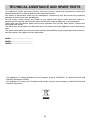
This appliance, before leaving the factory, has been carefully tested and regulated by expert and
specialized personnel in order to guarantee the best performances.
Any repairs or adjustments which may be subsequently required may only be carried out by qualified
personnel with the utmost care and attention.
For this reason, always contact your Dealer or your nearest After Sales Centre whenever repairs or
adjustments are required, specifying the type of fault and the model of appliance in your possession.
Please also note that genuine spare parts are only available from our After Sales Service Centres and
authorized retail outlets.
The above data are printed on the data label put on the inferior part of the appliance and on the packing
label.
The above informations give to the technical assistant the possibility to get fit spare parts and a heaven-
sent intervention. We suggest to fill the table below.
MARK: ................................................
MODEL: .............................................
SERIES: .............................................
This appliance is marked according to the European directive 2002/96/EC on Waste Electrical and
Electronic Equipment (WEEE).
This guideline is the frame of a European-wide validity of return and recycling on Waste Electrical and
Electronic Equipment.
TECHNICAL ASSISTANCE AND SPARE PARTS
24
-
 1
1
-
 2
2
-
 3
3
-
 4
4
-
 5
5
-
 6
6
-
 7
7
-
 8
8
-
 9
9
-
 10
10
-
 11
11
-
 12
12


Ask a question and I''ll find the answer in the document
Finding information in a document is now easier with AI
Related papers
Other documents
-
Ignis AKL 359/BR/02 Owner's manual
-
Whirlpool 6AKM 613/IX Program Chart
-
 Trieste TRV602WH Use & Installation Manual
-
Whirlpool AKM 925/BA Program Chart
-
-
-
-
-
-
Whirlpool AKM 900/NE/01 Program Chart
