Network Technologies UNIMUX-DVI-xHD User manual

Category
KVM switches
Type
User manual

Network Technologies UNIMUX-DVI-xHD is a high-quality KVM switch that allows you to control multiple computers from a single keyboard, mouse, and monitor. With support for up to 16 computers, the UNIMUX-DVI-xHD is perfect for small businesses, home offices, and anyone who needs to manage multiple computers simultaneously.

Key features:

  • Control up to 16 computers from a single keyboard, mouse, and monitor
  • Supports DVI video input and output
  • USB 2.0 connectivity
  • Rack-mountable design
  • Easy to install and use

Benefits:

  • Simplifies the management of multiple computers
  • Saves space on your desk
MAN005 Rev Date 6/6/2008
UNIMUX-DVI-xHD
USB DVI KVM Switch
Installation and Operation Manual
UNIMUX
TM
Series
NETWORK
TECHNOLOGIES
INCORPORATED
Tel:330-562-7070
Fax:330-562-1999
1275 Danner Dr
Aurora, OH 44202
www.networktechinc.com
NTI
R
i
TRADEMARK
UNIMUX is a trademark of Network Technologies Inc in the U.S. and other countries
COPYRIGHT
Copyright © 2000,2008 by Network Technologies Inc. All rights reserved. No part of this publication may be reproduced, stored
in a retrieval system, or transmitted, in any form or by any means, electronic, mechanical, photocopying, recording, or otherwise,
without the prior written consent of Network Technologies Inc, 1275 Danner Drive, Aurora, Ohio 44202.
CHANGES
The material in this guide is for information only and is subject to change without notice. Network Technologies Inc reserves the
right to make changes in the product design without reservation and without notification to its users.
CE Statement
We, Network Technologies Inc, declare under our sole responsibility that the UNIMUX-DVI-4/8/16 is in conformity with European
Standard EN55022.
Typographic Conventions
Typeface meaning Font Configuration Example
On-screen computer output Courier New-(not bold)
C:>
What you type on the computer Courier New-bold
C:>edit text.bat
<L> (press the “L” key)
.
ii
TABLE OF CONTENTS
INTRODUCTION............................................................................................................................................................. 1
MATERIALS .................................................................................................................................................................... 2
DEFINITIONS.................................................................................................................................................................. 3
FEATURES AND FUNCTIONS.......................................................................................................................................4
RACKMOUNTING INSTRUCTIONS............................................................................................................................... 5
To Mount to a Rack .....................................................................................................................................................5
INSTALLATION............................................................................................................................................................... 6
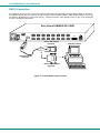
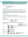
RS232 Connection.......................................................................................................................................................8
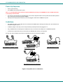
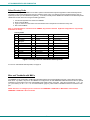
Power-Up Sequence.................................................................................................................................................... 9
Limitations.................................................................................................................................................................... 9
USING THE UNIMUX DVI KVM SWITCH .................................................................................................................... 10
Front Panel Control.................................................................................................................................................... 10
Keyboard Control.......................................................................................................................................................10
Command Mode ........................................................................................................................................................ 10
Scan Mode.............................................................................................................................................................. 11
Broadcast Mode...................................................................................................................................................... 11
Normal Mode ..........................................................................................................................................................11
No Sun Sleep Mode................................................................................................................................................ 11
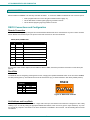
Select Country Code............................................................................................................................................... 12
Mice and Trackballs with MACs.............................................................................................................................. 12
RS232 CONTROL......................................................................................................................................................... 13
RS232 Connections and Configuration ..................................................................................................................... 13
Remote Connection ................................................................................................................................................ 13
Baud Rate ...............................................................................................................................................................13
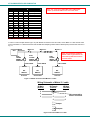
Unit Address and Loop Back .................................................................................................................................. 13
Command Protocol ................................................................................................................................................. 15
NTI Switch Control Program For Windows 9X, NT, 2000, XP, And Vista ................................................................. 16
SerTest- RS232 Interface Test Program ................................................................................................................... 16
Main Options........................................................................................................................................................... 16
KEYBOARD FEATURES .............................................................................................................................................. 18
Keyboard-To-Computer Translation .......................................................................................................................... 18
Translation Capabilities .......................................................................................................................................... 18
Translation Tables .................................................................................................................................................. 18
International Sun Keyboards .....................................................................................................................................19
TROUBLESHOOTING .................................................................................................................................................. 20
INDEX............................................................................................................................................................................ 20
WARRANTY INFORMATION........................................................................................................................................ 20
TABLE OF FIGURES
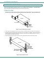
Figure 1- Secure rackmount ears to switch..................................................................................................................... 5
Figure 2- Secure switch to a rack.................................................................................................................................... 5
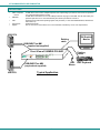
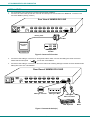
Figure 3- Connect a DVI monitor ....................................................................................................................................6
Figure 4- Connect the device(s)...................................................................................................................................... 6
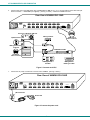
Figure 5- Connect each CPU .......................................................................................................................................... 7
Figure 6- Connect the power cord................................................................................................................................... 7
Figure 7- Connect RS232 control terminal...................................................................................................................... 8
Figure 8- Compatible device combinations ..................................................................................................................... 9
Figure 9- Country Codes for international SUN keyboards........................................................................................... 12
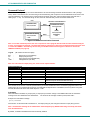
Figure 10- RS232 DIP switches ....................................................................................................................................13
Figure 11- RS232 connection with Matrix-Y-1 cable..................................................................................................... 14
Figure 12- Pinout of Matrix-Y-1 cable ........................................................................................................................... 14
Figure 13- RS232 Communication Illustrated ............................................................................................................... 15
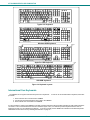
Figure 14- Keyboard Layouts........................................................................................................................................ 19
NTI UNIMUX SERIES USB KVM SWITCH
1
INTRODUCTION
The UNIMUX-DVI-xHD 4,8 or 16-Port USB DVI KVM switch (UNIMUX) allows access to up to sixteen (16) Windows, MAC, or
SUN USB CPUs from one USB keyboard and mouse and a DVI video-enabled monitor. Internal microprocessor circuitry allows
all USB CPUs to be booted simultaneously without keyboard error. Port selection is accomplished by front panel push buttons or
commands typed on the keyboard. Port lights and status LEDs continuously update on the front panel.
Types of User Input Devices Supported:
USB keyboard with Windows layout
USB keyboard with SUN layout
USB keyboard with MAC layout
USB Mouse - (up to 3 buttons)
USB IntelliMouse (scrollwheel)
USB Hub
Mouse-Trak trackball
Logitech, Kensington and Microsoft Wheelmouse or Trackball on Mac CPUs with special drivers
Logitech Cordless Elite Duo keyboard and mouse
Logitech wireless (S510, EX110, diNovo, LX710,MX5000)
Crystal Vision keyboard with touchpad
Gyration keyboard/mouse (Go 2.4)
NTI USB-PS/2-R Adapter
NTI USB-SUN-R Adapter
Kensington wireless (64379)
MS Wireless Optical Desktop (3000 and 4000)
HP P2360AA
Fellowes wireless keyboard (KBR0108) with mouse (MSR0238T)
Creative Desktop Wireless 8000
DVI monitors
Apple USB 2.0 Keyboard (MB110LL/A)
Apple USB 2.0 Mouse (MB112LL/A)
Types of CPUs Supported:
Any USB CPU supporting USB version 1.0 or above including:
USB WINxx
USB MAC
USB SUN
USB Linux
USB Unix
USB Free BSD
NTI UNIMUX SERIES USB KVM SWITCH
2
MATERIALS
Materials supplied with this kit:
NTI UNIMUX-DVI-xHD (4,8 or 16 ports) USB DVI Video KVM Switch
Line cord, country specific
Rack mount kit
CD with pdf file of this manual
1- DB9 Female-to-RJ45 Female adapter
1- DB25 Female-to-RJ45 Female adapter
1- 5 foot RJ45-to-RJ45 CAT5 patch cable
Materials Not supplied but REQUIRED:
USB-DHEXT-xx-MM cable for each CPU being connected to the switch- for DVI monitor, USB keyboard, and USB mouse
support- available in 3, 6,10, and 15 foot lengths
where:
xx is the length of the cable in feet
MM indicates male-to-male connector
Cables can be purchased from Network Technologies Inc by calling (800) 742-8324 (800-RGB-TECH) in the US and Canada or
(330) 562-7070 (worldwide).
HDMI Type A Male
USBType A Male
DVI-D-Male
Single Link
DVI-D-Male
USB Type A
Male
HDMI Type A
Male
USB-DHEXT-xx-MM
(3,6,10 and 15 foot cables available)
NTI UNIMUX SERIES USB KVM SWITCH
3
DEFINITIONS
USB Composite
Device
A USB device that contains multiple endpoints each representing input devices that cannot be separated
(i.e. a keyboard with a built-in mouse)
USB Hub
A USB device that allows one or more USB input devices to plug in to the USB. The hub has exactly one
upstream port with one or more downstream ports which input devices connect to
CPU
Enclosure that contains the operating system and processor (i.e. Sun with SPARCstation5, Windows 95
with Pentium II)
Input Device
Keyboard or Mouse
System
One or more CPUs connected to one or more switches controlled by one or more input devices
Front View of UNIMUX-DVI-8HD
USB Keyboard
USB
Mouse
DVI Enabled
Monitor
USB CPU
USB CPU
USB-DHEXT-xx-MM
Typical Application
Existing
cables
(required-not supplied)
USB-DHEXT-xx-MM
161514131211109
87654321
Scan
Command
Broa dcast
RS232
UNIMUX
R
DDC
NTI
R
Network Technologies Inc
Existing
cable
1
8
ON
NTI UNIMUX SERIES USB KVM SWITCH
4
FEATURES AND FUNCTIONS
1. RS232- DIP switches for configuring switch address when RS232 is used
2. DDC- for refreshing the DDC information between the monitor and CPU
3. CPU Select Switches- push to manually switch to a specific CPU or change the switch operating mode
4. CPU Status LEDs- for visual indication of connection between the user and a specific CPU.
5. Mode Status LEDs- for visual indication of switch operating mode
6. IEC Connector w/Built-in 2A 240VAC Replaceable Fuse- for attachment of the IEC power cord to power the UNIMUX
7. Switch- for powering ON and OFF the UNIMUX
8. RS232- RJ45 serial connector- for attachment of RS232 control cable
9. CPU x- HDMI Type A female connector- for connection of the cable from the CPU(s)
10. MONITOR- female DVI connector- for connecting DVI cable from user monitor
11. USB- USB type A female connector- for connection of user USB keyboard and mouse
9
Rear View of UNIMUX-DVI-16HD
13
5
Front View of UNIMUX-DVI-16HD
6
8
2
161514131211109
87654321
Scan
CommandBroadcast
RS232
UNIMUX
R
DDC
NTI
R
Ne twor k Tec hnolo gies Inc
CPU 1CPU 2CPU 3CP U 4CPU 5CPU 6CPU 7CP U 8
CPU 9CPU 10CPU 11CPU 12CPU 13CPU 14CP U 15CPU 16
RS232
250V,2A
MONITOR
NTI
Tel:330-562-7070
Fax:330-562-1999
1275 Danner Dr
Aurora, OH 44202
www.networktechinc.com
R
7 1110
4
18
ON
NTI UNIMUX SERIES USB KVM SWITCH
5
RACKMOUNTING INSTRUCTIONS
This NTI switch was designed to be mounted to a rack or to sit on a desktop. It includes rackmount ears to make attachment to a
rack easy, and rubber feet to be applied to the bottom of the case if it will instead sit on a flat surface. If this will sit on a flat
surface, simply apply the rubber feet to the bottom of the case in each of the 4 corners.
To Mount in a Rack
1. Attach the ears to the switch using the 6-32x3/16" flat Phillips-head screws (6) provided as shown in the illustration below.
The holes in the ears should line up with pre-threaded holes in the sides of the NTI switch. Tighten the screws securely.
Figure 1- Secure rackmount ears to switch
2. Install 4 cage nuts (not supplied) to the rack in locations that line up with the holes in the mounting ear on the NTI switch.
3. Secure the NTI switch to the rack using four rack screws (10-32, 12-24, M6, etc.- not supplied). Each screw should be of
sufficient length to go completely through the NTI mounting ear, rack frame and fully engage all threads in the cage nut.
Be sure to tighten all mounting screws securely.
4. Attach all cables securely to the switch and where necessary supply adequate means of strain relief for cables.
Figure 2- Secure switch to a rack
6-32x3/16"
Flat Head
Screws
(Provided)
Rackmount Ear
NTI Switch
Front of Switch
Cage Nuts
Rack Screws
Rack
(not supplied)
(not supplied)
NTI Switch
NTI UNIMUX SERIES USB KVM SWITCH
6
INSTALLATION
1. It is not necessary to turn the CPUs or monitors OFF during this installation.
2. Connect a DVI-to-DVI cable (should have come with the monitor) from a DVI monitor to the “MONTOR” connector on the
rear of the UNIMUX (See Fig. 3 below.)
Figure 3- Connect a DVI monitor
3. Connect the male USB type A connector on the keyboard cable to either one of the two USB type A female connectors
labeled with the USB symbol ( ) on the rear of the UNIMUX.
4. Connect the male USB type A connector on the mouse cable to the remaining USB type A female connector labeled with the
USB symbol on the rear of the UNIMUX.
Figure 4- Connect the device(s)
DVI Enabled
Monitor
Mating Face of
DVI Male
Rear View of UNIMUX-DVI-16HD
CPU 1CPU 2CPU 3CPU 4CPU 5CPU 6CPU 7CPU 8
CPU 9CPU 10CPU 11CPU 12CPU 13CP U 14CPU 15CPU 16
RS232
250V,2A
MONITOR
NTI
Tel:330-562-7070
Fax:330-562-1999
1275 Danner Dr
Aurora, OH 44202
ww w.n etwo rk tech inc. co m
R
DVI-D-Male
Existing Cable
USB Keyboard
USB
Mouse
USB Type A
Male Connectors
USB Type A Male
USB Type A Female
Rear View of UNIMUX-DVI-16HD
CPU 1CPU 2CPU 3CP U 4CPU 5CPU 6CPU 7CP U 8
CPU 9CPU 10CPU 11CPU 12CPU 13CPU 14CP U 15CPU 16
RS232
250V,2A
MONITOR
NTI
Tel:330-562-7070
Fax:330-562-1999
1275 Danner Dr
Aurora, OH 44202
www.networktechinc.com
R
NTI UNIMUX SERIES USB KVM SWITCH
7
5. Connect each CPU to the USB switch using a USB-DHEXT-xx-MM (xx=3, 6, 10, or 15 foot) cable for each video and input
device connection – REQUIRED (not supplied). (See Fig. 5 below.) Cables are available from NTI.
Figure 5- Connect each CPU
7. Connect the AC power cord with IEC connector to the UNIMUX. (See Fig. 6 below.)
Figure 6- Connect the power cord
USB Type A Female
USB Type A Male
DVI Female
Video Connector
Rear View of Windows USB CPU
Video Port
Input Device Port
HDMI Type A
Video Connector
Mating Face of
DVI Male
Mating Face of
HDMI Type A Male
Rear View of UNIMUX-DVI-16HD
CPU 1CPU 2CPU 3CPU 4CPU 5CPU 6CPU 7CPU 8
CPU 9CPU 10CPU 11CPU 12CPU 13CPU 14CPU 15CP U 16
RS232
250V,2A
MONITOR
NTI
Tel:330-562-7070
Fax:330-562-1999
1275 Danner Dr
Aurora, OH 44202
www.networktechinc.com
R
USB-DHEXT-xx-MM
(3,6,10 and 15 foot cables available)
Rear View of UNIMUX-DVI-16HD
CPU 1CPU 2CPU 3CP U 4CPU 5CPU 6CPU 7CP U 8
CPU 9CPU 10CPU 11CPU 12CPU 13CPU 14CP U 15CPU 16
RS232
250V,2A
MONITOR
NTI
Tel:330-562-7070
Fax:330-562-1999
1275 Danner Dr
Aurora, OH 44202
www.networktechinc.com
R
Power cord
IEC Connector
NTI UNIMUX SERIES USB KVM SWITCH
8
RS232 Connection
If the RS232 is going to be used, connect one end of the CAT5 patch cable (supplied) to the port labeled “RS232” on the rear of
the UNIMUX. Plug the other end of the CAT5 cable into either the RJ45-to-DB9 or RJ45-to-DB25 adapter supplied, and connect
the adapter to the RS232 port on the control terminal. Follow the instruction under “RS232 Control” on page 13 for configuration
and use of the RS232 control feature.
Figure 7- Connect RS232 control terminal
VGA
Multi-Scan
Monitor
Control Terminal
RJ45-to-DB9 Adapter
(supplied)
CAT5 Patch Cable
(supplied)
RJ45-to-DB25 Adapter
(supplied)
or
Rear View of UNIMUX-DVI-16HD
CPU 1CPU 2CPU 3CP U 4CPU 5CPU 6CPU 7CP U 8
CPU 9CPU 10CPU 11CPU 12CPU 13CPU 14CP U 15CPU 16
RS232
250V,2A
MONITOR
NTI
Tel:330-562-7070
Fax:330-562-1999
1275 Danner Dr
Aurora, OH 44202
www.networktechinc.com
R
NTI UNIMUX SERIES USB KVM SWITCH
9
Power-Up Sequence
Power-up the monitor(s).
The UNIMUX can be powered at any time.
Note: It is recommended that the monitor be powered-ON before powering on the UNIMUX in order for DDC information
to be properly communicated.
The CPUs can be powered at any time although if a CPU needs a keyboard and/or mouse at power-ON it should be powered
after connecting to and powering-ON the UNIMUX.
USB input devices (keyboard and mouse) can be hot plugged to and from the UNIMUX at any time.
Limitations
Only USB input device or hub cables can be connected to the UNIMUX at the USB Type A female ports. (See Features and
Functions on page 3, item 11.)
A USB hub (single or multi-port) can be used provided only USB input devices are plugged into it.
Only a USB Windows or SUN keyboard or USB mouse may be connected to the USB port on a USB MAC keyboard
A maximum of 8 input devices may be connected to the UNIMUX either directly or through hubs.
See Fig. 8 for some examples of input device combinations that can be used with the UNIMUX.
Figure 8- Compatible device combinations
USB Windows Keyboard
USB
Mouse
USB Type A
Male Connectors
USB MAC Keyboard
USB
Mouse
USB
Mouse
USB
Mouse
USB Windows Keyboard
Typical Installation- 1 keyboard, 1 mouse
Multiple keyboards and mice
MAC USB keyboard and mouse
USB
Hub
USB MAC Keyboard
USB
Mouse
MAC USB keyboard and mouse through hub
USB
Hub
NTI UNIMUX SERIES USB KVM SWITCH
10
USING THE UNIMUX DVI KVM SWITCH
Once the UNIMUX is properly connected, the UNIMUX will enable a connection to be made between the CPUs attached to its
VIDEO and CPU ports and the monitor and input devices attached to the MONITOR and USB Device ports. The LEDs on the
control panel of the UNIMUX will illuminate depending on which port (and corresponding CPU) is being connected to the monitor
and input devices.
The UNIMUX can be controlled by three methods:
front control panel using touch-switches and LEDs
keyboard control through Command Mode
RS232 control (page 13)
Front Panel Control
There is a touch-switch and LED on the front panel of the UNIMUX for each CPU the switch will connect the monitor and
input devices to. Pressing any touch-switch on the front panel of the UNIMUX will connect the corresponding CPU to the monitor
and input devices.
Holding down any front panel touch-switch for more than 2 seconds will cause the UNIMUX to cycle through all modes of
operation including COMMAND, BROADCAST, SCAN, and NORMAL (described in "Command Mode" below). The three MODE
LEDs on the front panel indicate which mode is selected. Release the touch-switch when the LEDs indicate the desired mode.
When no mode LEDs are illuminated the user is in Normal Mode controlling directly the CPU to which the user is connected
through the UNIMUX.
Keyboard Control
Keyboard control of the UNIMUX can be achieved using Command Mode (below). The keyboard can be used to control all
functions of the UNIMUX as an alternative to using the front panel on the UNIMUX.
By pressing <Ctrl> + < ` > (accent/tilde key), the user can enter Command Mode. Once in Command Mode, typing a series of
commands will cause the UNIMUX to connect the user to any one CPU connected to the switch. Pressing the <Esc> key will exit
Command Mode.
Command Mode
In order to control the UNIMUX with the keyboard connected, Command Mode must be enabled. To enter Command Mode from
the keyboard:
Press
When the COMMAND LED is illuminated, all 3 status lights on the keyboard will illuminate (if they aren't already due to caps lock,
scroll lock, and/or num lock) to indicate that Command Mode is enabled and the following functions are available:
Basic Command Functions
Function: Keystroke:
Increment Port
Decrement Port
Toggle Scan Mode
ON and OFF
Toggle Broadcast Mode
ON and OFF
Sets scan time-out
period for each port.
CHORDED SEQUENCE- PRESS CONSECUTIVELY
AND KEEP KEYS PRESSED UNTIL ALL ARE PRESSED.
+
-
PRESS CONSECUTIVELY
or
PRESS EITHER KEY
KEY SYMBOLS LEGEND:
D
or
(select the next lower port
ex. 02 01)
S
(The SCAN Mode LED will
also toggle ON and OFF)
T
-
-
(xxx from 002 to 255. ie. T002
would set the time-out period
for 2 seconds)
-
(0-2)
x
(0-9)
x
(0-9)
x
B
(The Broadcast Mode LED
will toggle ON and OFF.)
I
(select the next higher port
ex. 03 04)
or
`
Ctrl
~
(ACCENT/TILDE
KEY)
`
NTI UNIMUX SERIES USB KVM SWITCH
11
Selects a specific
port
Configure port to connect
To a MAC CPU
Configure port to connect
To a WINDOWS or SUN
CPU
Exit Command Mode
Scan Mode
To activate Scan Mode press <S> from the Command Mode menu. When in Scan Mode the switch scans to each port with a
CPU powered-ON. (The SCAN LED on the front panel will illuminate and remain ON while in Scan Mode. ) The port with the CPU
powered-ON remains active while in use until it becomes idle for the configured dwell time (default time-out period is 5 seconds)
before switching to the next powered-ON CPU port. See Command Mode section above for configuring the scan dwell time.
Note: The keyboard and mouse must remain idle for the full scan dwell time before the switch selects the next active
port.
Broadcast Mode
To activate Broadcast Mode press <B> from the Command Mode menu. (The BROADCAST LED on the front panel will illuminate
and remain ON while in Broadcast Mode.) Broadcast Mode enables the user to type characters to all powered-ON CPUs
simultaneously.
Note: The user must type somewhat slowly when in Broadcast Mode (less than 20 wpm) and cannot use the
<Backspace> key.
Normal Mode
When all of the UNIMUX mode LEDs are OFF the user is in Normal Mode, controlling the CPU to which the user is connected
through the UNIMUX.
No Sun Sleep Mode
Note: It is necessary to configure a Sun CPU (most versions) such that the Sleep Mode is not enabled. If the Sun CPU
goes into Sleep Mode either automatically or manually, the user must reboot the Sun CPU in order to resume use of the
Sun CPU.
To disable the Sleep Mode, perform the following steps:
1. Select "Power Manager"
2. Look for "Device Idle Time Before Power Saving Starts"
3. Select "Always ON"
4. Look for "Override Device Idle Time For:"
5. Make sure neither "Monitors" nor "Disks" are selected.
P
-
-
(Pxx would be P01, P02, etc.)
(0-9)
x
(0-9)
x
Esc
FYI: The user must exit Command Mode to type to a CPU.
To exit Command Mode, either hold down any touch-switch on the
front panel for more than 2 seconds, OR press <ESC> on the
keyboard.
+
M
x
(xx= 01-8 <M> + <0> + <1> will enable function on Port 1
<M> + <0> + <4> will enable function on Port 4. Keyboard
LED's will flash once to confirm command. )
+
x
+
W
x
(xx= 01-8 <W> + <0> + <1> will disable function on Port 1
<W> + <0> + <4> will disable function on Port 4. Keyboard
LED's will flash once to confirm command. )
x
+
NTI UNIMUX SERIES USB KVM SWITCH
12
Select Country Code
It is possible to configure the UNIMUX to emulate a specific international Sun keyboard regardless of what actual keyboard is
connected. This is recommended when the CPU needs the layout code (i.e. a SUN CPU) and the keyboard doesn't have an
explicit layout code (i.e. some Windows keyboards). To do this, manually set the UNIMUX to indicate the international keyboard
identification number to the CPU using the following procedure;
1. Connect the keyboard to be used to the UNIMUX
2. Enter Command Mode
3. Type Lxx, where xx is the number from the list below that corresponds to the desired country code
4. Exit Command Mode
Note: If any SUN CPUs are connected to the UNIMUX, they must be rebooted. Keyboard configuration is only read by
SUN CPUs on startup.
Country Codes
00 Auto Detect 13 International (ISO) 26 Swedish
01 Arabic 14 Italian 27 Swiss/French
02 Belgian 15 Japan (Katakana) 28 Swiss/German
03 Canadian-
Bilingual
16 Korean 29 Switzerland
04 Canadian-French 17 Latin American 30 Taiwan
05 Czech Republic 18 Netherlands/Dutch 31 Turkish
06 Danish 19 Norwegian 32 UK
07 Finnish 20 Persian (Farsi) 33 US
08 French 21 Poland 34 Yugoslavia
09 German 22 Portuguese
10 Greek 23 Russia
11 Hebrew 24 Slovakia
12 Hungary 25 Spanish
Figure 9- Country Codes for international SUN keyboards
For more on international SUN keyboards, see page 19.
Mice and Trackballs with MACs
The UNIMUX can be configured to enable full functionality between mice and trackballs having two or more buttons and USB
MAC CPUs. By default, the ports on the UNIMUX are configured for use with WINDOWS and SUN CPUs and have no special
translation for using multi-function mice and trackballs when a MAC CPU is connected. Using the commands <M> + <x> + <x>
(xx = port number), or <W> + <x> + <x> in Command Mode (page 10), either enable or disable this feature as needed for each
port.
NOTE: Be sure to re-configure port for connection to a WINDOWS or SUN CPU if a MAC CPU is removed and a
WINDOWS or SUN CPU is then connected.
NTI UNIMUX SERIES USB KVM SWITCH
13
RS232 CONTROL
RS232 enables the UNIMUX to be remotely controlled via RS232. To control the UNIMUX via RS232 the user has three options:
write a program that runs on a PC using the Command Protocol (page 15)
use the NTI Switch Control Program (page 16) provided on the CD
use the SerTest program (page 16) provided on the CD
RS232 Connections and Configuration
Remote Connection
The RS232 Interface (optional) is designed to meet the RS232C standard and can be controlled from any CPU or other controller
with an RS232 communications port. The pin-out for the RJ45 connector on the unit is as follows:
RS232 (RJ45) CONNECTOR
PIN SIGNAL FUNCTION
1 - No connection
2 - No connection
3 RX+ Receive data (TXD at host)
4 GND Ground
5 - No connection
6 TX+ Transmit data (RXD at host)
7 - No connection
8 - No connection
A 5 foot patch cable and two adapters, RJ45-to-DB9 and RJ45-to-DB25, have been provided for connection to most CPUs (see
page 8).
Baud Rate
The baud rate can be changed by powering down the unit, changing the 8 position RS232 DIP switch on the front of the UNIMUX,
and then powering back up. This table shows how to set the baud rate. (Fig. 10 shows switches in their factory default position.)
DIP
SWITCH
BAUD RATE
3 2
OFF OFF 2400
OFF ON 9600 (default)
ON OFF 19200
ON ON 38400
Figure 10- RS232 DIP switches
Unit Address and Loop Back
To allow multiple units to be controlled from a single CPU serial port, the RS232 control interface is designed to allow "daisy
chaining" up to 15 units. By setting the appropriate RS232 DIP switches, each unit can be given a unique address (1-15). Then
the unit will only respond to commands on the bus if its address is embedded in the command. Use the following table to set the
unit address.
RS232
1
8
ON
NTI UNIMUX SERIES USB KVM SWITCH
14
DIP SWITCH UNIT ADDRESS
8 7 6 5
OFF OFF OFF OFF 0 (not valid)
OFF OFF OFF ON 1 (default)
OFF OFF ON OFF 2
OFF OFF ON ON 3
OFF ON OFF OFF 4
OFF ON OFF ON 5
OFF ON ON OFF 6
OFF ON ON ON 7
ON OFF OFF OFF 8
ON OFF OFF ON 9
ON OFF ON OFF 10
ON OFF ON ON 11
ON ON OFF OFF 12
ON ON OFF ON 13
ON ON ON OFF 14
ON ON ON ON 15
Note: Switch 4 on the RS232 DIP switch is not used.
In order to connect multiple switches (up to 15) with RS232 connections to the same CPU, an NTI Matrix-Y-1 cable must be used.
Connect the Matrix-Y-1 cable between the RJ45-to-DB9 serial adapter (provided with the RS232 option) and the CPU as shown in
Fig. 11.
Figure 11- RS232 connection with Matrix-Y-1 cable
Figure 12- Pinout of Matrix-Y-1 cable
(Unit #1)
(Source)
23
33
555
22
7
8
1
4
6
Jumper
Jumpers
Not connected to
source connector
(Unit #2)
9D Female9D Male 9D Male
Wiring Schematic of Matrix-Y-1 cable
Note: The "loop back" RS232 DIP switch (RS232 DIP
switch 1) should be ON for each unit in the chain.
NTI
SWITCH
CPU
RS232
First Unit
NTI
SWITCH
RS232
NTI
SWITCH
RS232
Second Unit Last Unit
RS232
Serial Port
Matrix-Y-1
Matrix-Y-1 Matrix-Y-1
RJ45
TO DB9
SERIAL
ADAPTER
RJ45
TO DB9
SERIAL
ADAPTER
RJ45
TO DB9
SERIAL
ADAPTER
CAT5 CABLE CAT5 CABLE CAT5 CABLE
Note: The maximum combined
RS232 cable length between the
CPU and any NTI switch cannot
exceed 15 feet.
NTI UNIMUX SERIES USB KVM SWITCH
15
Command Protocol
RS232 commands supported by the unit are defined below. All command strings should be terminated with a <CR> (carriage
return). When a command is sent, the entire string is echoed back along with a response from the addressed unit as shown in the
command definitions. All characters in the command string should be upper case, and all numbers below 10 should have a
leading 0 (ex: 1 = 01). As command strings are sent, the inner character delay cannot exceed 500 milliseconds.
Figure 13- RS232 Communication Illustrated
Note: To use this command protocol, the user is required to write a program that will send an entire command string all
at once, not character by character. Programs that send one character at a time (such as HyperTerminal) cannot be used
to control the UNIMUX. Alternatively, the user may use the NTI Switch Control Program or SerTest to control the
UNIMUX via RS232 (see page 16).
Legend: (All numbers must be two digits)
SW : Switch (01-15) (Unit Address)
OP : Output (User) Port (01)
IP : Input (CPU) Port (01-MAXINPUTS)
<CR> : Carriage Return (Hex 0xD)
Note: For units with one output (user) port, use 01 for the output selection.
Command Definitions
Command String Good Response Description
CS SW,IP,OP *<CR> Connect Output (User) Port To specific Input (CPU) Port
RO SW,OP *<CR>IP<CR> Read Connection For Output (User) Port to Input (CPU) Port
RS SW *<CR> Internal Reset
RU SW *<CR>IP,OP<CR> Read Unit Size
SS SW,00 *<CR> Disable Autostatus feature (see below)
SS SW,01 *<CR> Enable Autostatus feature (see below)
GO SW,OP *<CR>go SW,OP:IP<CR> Read connection of a Output (User) Port to Input (CPU) Port
(different response format than RO command)
GM SW,00 *<CR>go OP,IP (all ports)<CR> Read connection matrix of all Output (User) ports
If the first field is not a known command (as listed above) or SW field is different from the unit address programmed at the DIP
switch (page 13), the command will be ignored. If the SW field corresponds to the unit address, but if the syntax is wrong after
this field, the switch will answer with a bad response ?<CR>.
Autostatus
When Autostatus is enabled, any output (user) -to-input (CPU) connection change in the UNIMUX will cause an Autostatus
message to be sent via RS232 to the administrator. The format of the message would be "pc SW,OP:IP<CR>"
Example of an Autostatus message:
pc 01,01:04<CR>
which means "At the switch with unit address 01, the output (User) (01) has changed connection to input (CPU) port 04."
Note: An Autostatus message to the administrator will be delayed by any RS232 traffic being received by the switch
from the administrator.
By default, Autostatus is disabled and must be manually enabled.
CS 01,01,03<CR>
CS 01,01,03<CR>
(COMMAND RECEIVED)
(RESPOND)
* <CR>
(COMMAND SENT)
(RESPONSE RECEIVED)
CS 01,01,03<CR>
* <CR>
CPU
SWITCH AT UNIT ADDRESS 01
RS232
RS232
(ECHO)
CS 01,01,03<CR>
NTI UNIMUX SERIES USB KVM SWITCH
16
NTI Switch Control Program For Windows 9X, NT, 2000, XP, And Vista
The NTI Switch Control Program is an easy and powerful graphical program that controls NTI switches through an RS232
interface. The NTI Switch Control Program is included on the CD packaged with the UNIMUX. The NTI Switch Control
Program is downloaded by clicking on the link "Download NTI Switch Control Program".
To install the NTI Switch Control Program after downloading
1. Locate the Setup.exe in the directory the program was downloaded to and double-click on it
2. Follow the instructions on the screen
Note: In order to use the NTI Switch Control Program to control the UNIMUX, the UNIMUX RS232 port must be set at a
baud rate of 9600 bps (see page 13).
The NTI Switch Control Program performs best on monitors set to a screen resolution of at least 800 X 600. Instruction for using
the NTI Switch Control Program is available by opening "MSCP Help" in the "NTI" program group once the program has been
installed and is open on the screen.
To open "MSCP Help" from the Windows desktop
1. Click on START
2. Click on PROGRAMS
3. Click on NTI
4. Click on MSCP Help
SerTest- RS232 Interface Test Program
This software allows a user to test the functions of an NTI server switch, matrix switch or Multi-user/Multi-platform/Single-user
switch RS232 interface. The SerTest program is automatically loaded when installing the NTI Switch Control Program as
described above. The SerTest program, located in the NTI program group, generates a main menu with the 4 selections
described below:
Main Options
Switch Operations
- send commands to the unit.
Ethernet Operations
- set ethernet connection variables (not applicable to this model)
Setup Options
- set COM port, baud rate, and unit address
About SerTest
- display the program version
If Matrix Operations is selected, the following menu is displayed:
SWITCH OPERATIONS
1) Reset Unit
- send a reset command to the switch
- the current unit address is displayed in parentheses
2) Reset All Units
- send an internal reset command to all switches
3) Connect Output/User to an Input/CPU
- connect an output to an input
4) Connect All Outputs/Users to an Input/CPU (not applicable to this model)
- connect all outputs to an input
5) Connect Audio Output/User to an Input/CPU (not applicable to this model)
- connect an output to an input
6) Connect All Audio Outputs/Users to an Input/CPU (not applicable to this model)
- connect all outputs to an input
7) Change Mute Status for Audio Output/User (not applicable to this model)
- mute or un-mute the Audio port output
NTI UNIMUX SERIES USB KVM SWITCH
17
8) Change Volume for Audio Output/User (not applicable to this model)
- change Audio port output volume
9) Read Connection for Output/User
- read what input is connected to the specified output
a) Read Connection for Audio Output/User (not applicable to this model)
- read what input is connected to the specified output
b) Read Mute Status and Volume for Audio Output/User (not applicable to this model)
- read the volume and the mute status of the specified output
c) Read Unit Size
- read the switch size (number of inputs and outputs)
d) Read Unit Version/Revision String (not supported by this model)
- read a string containing the switch version, type, and size
e) Save I/O Connections into Unit Memory (not applicable to this model)
- save the connections into switch memory bank
f) Restore I/O Connections from Unit Memory (not applicable to this model)
- restore the connections from switch memory bank
g) Save All Units I/O Connections into Units Memory (not applicable to this model)
- save the connections into switch memory bank, command for all switches
h) Restore All Units I/O Connections from Units Memory (not applicable to this model)
- restore the connections from switch memory bank, command for all switches
i) Change All Units Baud Rate (9600/COM1)
- change RS232 Baud rate of all switches
- the current baud rate and serial port are displayed in parentheses
ETHERNET OPERATIONS (not applicable to this model)
SETUP OPTIONS
1) select Com port current: (COM1:)
- select PC serial port
- the current PC serial port is displayed in parentheses
2) select Baud rate current: (9600)
- select PC serial port baud rate
- the current baud rate is displayed in parentheses
3) set unit Address current: (1)
- select the unit address of the switch to be connected to by this program
- the current address is displayed in parentheses
For any selection that requires user input, the user is prompted. When commands are sent to the UNIMUX, the command string
and UNIMUX responses are echoed to the screen. All commands generated by the program are formatted according to the
information provided in sections above. If any transmission problems are detected, an error message is displayed.
Press <Esc> or <Enter> to back out to the main menu and press again to exit.
  • Page 1 1
  • Page 2 2
  • Page 3 3
  • Page 4 4
  • Page 5 5
  • Page 6 6
  • Page 7 7
  • Page 8 8
  • Page 9 9
  • Page 10 10
  • Page 11 11
  • Page 12 12
  • Page 13 13
  • Page 14 14
  • Page 15 15
  • Page 16 16
  • Page 17 17
  • Page 18 18
  • Page 19 19
  • Page 20 20
  • Page 21 21
  • Page 22 22
  • Page 23 23

Network Technologies UNIMUX-DVI-xHD User manual

Category
KVM switches
Type
User manual

Network Technologies UNIMUX-DVI-xHD is a high-quality KVM switch that allows you to control multiple computers from a single keyboard, mouse, and monitor. With support for up to 16 computers, the UNIMUX-DVI-xHD is perfect for small businesses, home offices, and anyone who needs to manage multiple computers simultaneously.

Key features:

  • Control up to 16 computers from a single keyboard, mouse, and monitor
  • Supports DVI video input and output
  • USB 2.0 connectivity
  • Rack-mountable design
  • Easy to install and use

Benefits:

  • Simplifies the management of multiple computers
  • Saves space on your desk

Ask a question and I''ll find the answer in the document

Finding information in a document is now easier with AI