MODEL
T250S-F16P
16 Gauge Straight
Finish Nailer
IMPORTANT!
DO NOT DESTROY
It is the customerʼs responsibility to have all
operators and service personnel read and
understand this manual.
OPERATING MANUAL AND
TOOL SCHEMATIC
P
Part No. 515500
219495-1
08/17
PRINTED IN TAIWAN
© 2017, Illinois Tool Works Inc.

2
INTRODUCTION
The PASLODE
®
T250S-F16P
finish nailer is a quality-built tool designed for use in residential
trim applications. This tool will deliver efficient, dependable performance when used according
to the manufactures guidelines. Please study this manual including the safety instructions to
fully understand the operation of this tool.
TOOL AND FASTENER SPECIFICATIONS ....................................................... 3
SAFETY INSTRUCTIONS ...................................................................................4
TOOL OPERATION ..............................................................................................5
EXPLODED VIEW AND SPARE PARTS LIST ..............................................10-11
ACCESSORIES ..................................................................................................12
TOOL WARRANTY AND LIMITATIONS
Paslode warrants that newly purchased power
fastening tools, parts and accessories will be free
from defects in material and workmanship for the
period shown below, after the date of delivery to
the original user.
ONE-YEAR FULL WARRANTY
A one-year warranty will apply to all parts, except
those which are specifically covered by an extended
warranty.
FIVE-YEAR EXTENDED LIMITED WARRANTY
A
five-year warranty will apply to all housing and cap
assembly castings.
WARRANTY STATEMENT
This warranty is limited to tools sold and service requested
in the United States. To obtain information on warranty
service in the United States, refer to the Service Center
listing that was provided with your tool.
Paslode's sole liability hereunder will be to replace any part
or accessory which proves to be defective within the specific
time period. Any replacement part or accessory provided in
accordance with this warranty will carry a warranty for the
balance of the period of warranty applicable to the part it
replaces. This warranty does not apply to part replacement
required due to normal wear.
This warranty is void as to any tool which has been subjected
to misuse, abuse, accidental or intentional damage, use with
fasteners,not meeting
Paslode specification, size, or quality,
repaired with other than genuine
damaged in transit or handling, or
has been altered or repaired in a
from the performance of the tool.
PASLODE MAKES NO WARRANTY, EXPRESSED OR
IMPLIED, RELATING TO MERCHANTABILITY, FITNESS, OR
OTHERWISE, EXCEPT AS STATED ABOVE, and Paslode's
liability AS STATED ABOVE AND AS ASSUMED ABOVE is
in lieu of all other warranties arising out of, or in connection
with, the use and performance of the tool, except to the extent
other wise provided by applicable law. PASLODE SHALL IN
NO EVENT BE LIABLE FOR ANY DIRECT, INDIRECT, OR
CONSEQUENTIAL DAMAGES, INCLUDING, BUT NOT
LIMITED TO, DAMAGES WHICH MAY ARISE FROM LOSS
OF ANTICIPATED PROFITS OR PRODUCTION, SPOILAGE
OF MATERIALS, INCREASED COST OF OPERATION, OR
OTHERWISE.
improperly maintained,
Paslode replacement parts,
which, in Paslode's opinion,
way that affects or detracts
Paslode reserves the right to change specifications, equipment, or
designs at any time without notice and without incurring obligation.

TOOL SPECIFICATIONS
MODEL NO. T250S-F16P (Part# 515500)
HEIGHT 11.6"
WIDTH 2.9"
LENGTH 12.3"
WEIGHT 3.9lbs.
OPERATING PRESSURE 80 to 120 p.s.i. (5.5 to 8.3 bars)
FASTENER SPECIFICATIONS
TOOL AIR FITTINGS:
This tool uses a 1/4” N.P.T. male plug. The inside diameter should be .28” (7mm)
or larger. The fitting must be capable of discharging tool air pressure when
disconnected from the air supply.
OPERATING AIR PRESSURE:
80 to 120 p.s.i. (5.5 to 8.3 bars). Select the operating air pressure within this range
for best tool performance.
DO NOT EXCEED THIS RECOMMENDED OPERATING PRESSURE.
NAIL LENGTH 1" - 2-½"
SHANK DIAMETER 16 gauge
TOOL AND FASTENER SPECIFICATIONS
3

4
WARNING
Failure to follow any of the above instructions could result in severe personal
injury to tool user and bystanders or cause damage to tool and property.
Contact your local Paslode Representative for presentation of Paslodeʼs Safety Awareness Program
SAFETY INSTRUCTIONS
SAFETY FIRST
These safety instructions provide information necessary
for safe operation of Paslode
®
tools.
DO NOT ATTEMPT
TO OPERATE THE TOOL UNTIL YOU READ AND
UNDERSTAND ALL SAFETY PRECAUTIONS AND
MANUAL INSTRUCTIONS.
WEAR EYE AND HEARING PROTECTION
Always wear hearing and eye protection devices, that
conform to ANSI Z87.1 requirements, when operating
or working in the vicinity of a tool. As an employer you
are responsible for enforcing the use of eye protection.
Wear hard hats in environments that require their use.
THE TOOL MUST BE USED ONLY FOR THE PUR-
POSE FOR WHICH IT WAS DESIGNED
Do not throw the tool on the floor, strike the housing in
any way or use the tool as a hammer to knock material
into place.
NEVER ENGAGE IN HORSEPLAY WITH THE TOOL
The tool is not a toy so do not use it like one. Never
engage in horseplay with the tool or point it at yourself
or any other person, even if you think it is not loaded.
NEVER ASSUME THE TOOL IS EMPTY
Check the magazine for fasteners that may be left in the
tool. Even if you think the tool is empty or disconnected,
never point it at anyone or yourself. Unseen fasteners
could fire from the tool.
NEVER CLAMP THE TRIGGER IN A LOCKED OR
OPERATING POSITION
The trigger of the tool must never be tampered with,
disabled or clamped in a locked or operating position
since this will cause the tool to drive a fastener any time
the work contacting element depressed.
DO NOT LOAD FASTENERS WITH THE AIR LINE
CONNECTED, OR WITH THE TOOL TRIGGER OR
WORK CONTACTING ELEMENT DEPRESSED
When loading fasteners into the tool be sure you
disconnect the air line and that you do not depress
the trigger or work contacting element.
OPERATE THE TOOL ONLY ON A WORKPIECE
The tool should be operated only when it is in contact
with the workpiece. Even then you should be careful
when fastening thin material or working near the edges
and corners of the workpiece since the fasteners may
drive through or away from the workpiece.
DO NOT DISABLE OR REMOVE THE WORK
CONTACTING ELEMENT
This tool is equipped with a safety mechanism, called a
work contacting element, to help prevent accidental
firing. Never tamper with, disable or remove the work
contacting element. Do not use the tool unless the work
contacting element is working properly. The tool could
fire unexpectedly.
DISCONNECT THE TOOL WHEN NOT IN USE
Always disconnect the tool from the air line when it
is not in use, when you leave the work area or when
moving the tool to a new location. The tool must
never be left unattended because people who are
not familiar with the tool might handle it and injure
themselves or others.
CARRY THE TOOL ONLY BY THE HANDLE
Always carry the tool by the handle only. Never carry
the tool by the air hose or with the trigger depressed
since you could drive a fastener unintentionally and
injure yourself or someone else.
DO NOT WEAKEN THE TOOL HOUSING
The tool housing is a pressure vessel and should never
be weakened by having your companyʼs name, area of
work or anything else stamped or engraved into its
surface.
DISCONNECT THE TOOL WHEN PERFORMING
REPAIRS AND CLEARING JAMS
Never attempt to clear a jam or repair a tool unless you
have disconnected the tool from the air line and removed
all remaining fasteners from the tool.
ALWAYS USE THE PROPER FITTING FOR THE
TOOL
Only MALE pneumatic type air connectors should be
fitted to the tool, so that high pressure air in the tool is
vented to atmosphere as soon as the air line is dis-
connected.
NEVER install FEMALE quick disconnect couplings on
the tool. Female couplings will trap high pressure air in
the tool when the air line is disconnected, leaving the
tool charged and able to drive at least one fastener.
DO NOT EXCEED THE MAXIMUM RECOMMENDED
AIR PRESSURE
.erusserp ria dednemmocer eht ta ylno loot eht etarepO
Do not exceed the maximum air
pressure marked on
the tool. Be sure the air pressure gauge is operating
properly and check it at least twice a day.
Never use any bottled air or gases such as oxygen to
operate the tool since they could cause the tool to
explode. Do not operate in explosive atmospheres.
INSPECT TOOL FOR PROPER OPERATION
USE ONLY PASLODE RECOMMENDED PARTS AND
FASTENERS
Use only parts and fasteners specifically designed and
recommended by Paslode for use in the tool and for
work to be done. Using unauthorized parts and fasteners
or modifying the tool in any way creates dagerous
situations. Replace all missing warning labels. Refer
to tool schematic for correct placement and part number.

Fasteners
T
he Paslode T250S-F16P Finish Nailer drives
Paslode
®
16 gauge fasteners designed to be used
with the tool. The use of fasteners that do not meet
Paslode standards could cause tool damage and
will void all warranty claims.
Loading Fasteners
STEP 1: Align the heads of the Paslode 16 ga.Finish
nails to the brad channel in the rear of the magazine
and insert one or two strips. Push the nails strips
forward.
STEP 2: Next,
pull the follower toward the rear of the
until the follower passes the last strip of
Release the follower and let the follower
push the nails forward into the nose of the tool.
When the follower reaches the reload area, marked
on the side of the magazine, you may insert a new
strip of nails. When the follower arrow reaches the
lockout area the tool automatically locks the tool to
prevent the tool from operating. To unlock the tool,
simply reload another strip of nails.
Depth of Drive Adjustment
Disconnect the air supply.
The depth of drive adjustment is done by turning the
adjustment wheel located below the trigger.
Clearing a Jam
An occasional problem you may encounter is a jammed
fastener. Because of the unique design of the Paslode
Finish Nailer, clearing a jammed fastener is easy:
1. Disconnect the air supply.
2. Pull the latch, releasing front guide. Pivot front guide
forward.
3. Clear jam, and push driver blade back up to its normal
position.
4. Close front guide and latch it. Check that work
contacting element moves freely.
TOOL OPERATION
5
Lockout Feature
The purpose of this feature is to prevent needless
blank cycling, which could mar woods and damage
tool components.
Ten (10) nails will be left in the
magazine when the follower reaches the lockout
area. When changing fastener length or loading
at the beginning of the work day, you should inspect
the magazine and nose for any fasteners left in the
tool.
These nails will not be
visible unless you open
the nose of the tool.
magazine
fasteners.
–
–
+

TOOL OPERATION
Trigger Methods:
The Paslode T250S-F16P Finish Nailer has a triggering
system than can be switched from sequential to contact
trip.
T
o switch the trigger, press in the round button
on the left side of the trigger and rotate the right side
of the button to the desired triggering method. The TTT
indicates contact trip and the
T indicates sequential
operation.
Successive (Bounce) Driving -
Grasp the handle firmly.
Squeeze the trigger and move the tool along the work-
piece with a bouncing motion, depressing the work con-
tacting element at the points where you want to drive a
fastener.
Keep the trigger depressed and continue to bounce the
work contacing element against the workpiece, position-
ing the tool above as carefully as possible.
When the desired number of fasteners have been
driven, release the tool trigger to avoid unintentional
fastener discharge.
6
Reversible Belt Hook:
The belt hook can be changed from the left hand side of the
tool to the right hand side.
To change the position, squeeze
the base of the belt hook and remove it from the tool and tool
and position it on the desired side.
Sequential Operation -
The sequential setting T prevents succesive or "bounce"
driving.
Depress the work contacting element and hold it
against the work surface before pulling the trigger.
After each fastener is driven, completely release the
trigger and lift the tool from the work surface.
Sequential
Operation
Successive (Bounce)
Driving
Trigger select
indicator
Unload Nails:
magazine and press the center lock button on the follower.
magazine. To release the lock simply pull the follower back
move forward.
To unload nails, simply pull the follower to the rear of the
The lock will move the follower out of the way and allow
nails to slide past the follower and out of the rear of the
and the lock button will release and allow the follower to

7
MAINTENANCE
Paslode
®
tools are built for ease of maintenance. A few
simple details will assure trouble-free operation and long
tool life. Anyone who uses or maintains the tool must read
the safety and maintenance instructions. Study the sche-
matic drawing before starting any repairs on the tool.
Air-operated tools must be inspected periodically, and worn
or broken parts must be replaced to keep the tool operating
safely and efficiently. Also the items on the maintenance
chart must be checked often.
Cold Weather Care
When temperatures are below freezing, tools should be
kept warm by any convenient, safe method. If this is not
possible, the following procedure should be used to warm
up the tools.
❑ Reduce the regulated air pressure to 30 psi.
❑ Remove all fasteners from the tool.
❑
Collect an air line and blank fire the tool. The reduced
air pressure will be enough to free-
fi
re the tool. Slow speed
operation tends to warm up the moving parts. Slowing up
the piston helps the bumper and the O-rings to become
springy.
❑ Once the tool is warmed up, readjust the regulator to
the proper working pressure and reload the tool.
❑
Open the drain on the air compressor tank to drain any
moisture at least daily in extremely cold or humid weather.
A few ounces of anti-freeze in the tank will keep the air
free of frost.
Testing the Tool After Servicing
After replacing any part or parts, it is important to check
the tool for proper operation. This ensures that the tool
was put together correctly, is safe to use, and will perform
the job properly.
❑ Ensure that all hardware is tight.
❑
Ensure that the work contacting element is installed
correctly in relation to the trigger, and that both parts move
freely.
❑ Ensure that the magazine is properly attached.
❑
Ensure that the required safety information on the tool
is legible.
❑
Use only Paslode approved fasteners in the tool, and
ensure that they are correct for the application.
❑
Ensure that a male air fitting is securely connected to
the tool.
❑
Test the tool by driving fasteners into a workpiece iden-
tical to the tool's application.
❑
Check the tool for air leaks during testing and for the
proper sequence of operation.
❑
Ensure that all fasteners are driven to the same depth
and that the crown of the fastener is flush with the work-
piece.
Most minor problems can be resolved quickly and easily
using the maintenance table that follows. If problems per-
sist, contact your Paslode dealer for assistance.

MAINTENANCE
Drain air line filter (daily).
Clean filter element, then blow
air through filter in direction
opposite to normal flow.
Check that all screws on tool
are tight.
Keep work contacting element
working properly.
Keep magazine and feeder
mechanism clean.
Use only Paslode replacement
parts.
WOHYHWNOITCA
Prevent accumulation of
moisture and dirt.
Prevent clogging of filter with
dirt.
Prevent air leakage and pro-
mote efficient operation.
Promote operator safety and
efficient tool operation.
Prevent jamming of fasteners.
Keep tool operating efficiently
and maintain Paslode tool
warranty.
Open manual petcock (most
air supply systems have such
a valve).
Wash with soap and water or
follow manufacturers instruc-
tions.
Check screws daily.
Blow clean daily.
Blow clean daily.
Order any replacement parts
needed from Paslode Dealer.
8

OPERATOR TROUBLESHOOTING
PROBLEM CORRECTIVE ACTION
Fasteners will not drive completely into wood.
Fasteners penetrate properly during normal
operation, but won't drive fully at faster speeds.
Fasteners drive too deeply into wood.
Fastener jams in nose of tool.
Tool skips during operation - no fasteners are driven
from time to time.
Tool operates, but no fasteners are driven.
Air leaks at cap when tool is connected to air.
Adjust the
depth of drive adjustment (retract length).
Increase air pressure (do not exceed 120 psi).
Increase air flow to tool -- use larger air lines
(3/8 inch ID minimum).
Adjust the
depth of drive adjustment (extend length).
Reduce air pressure.
Open front guide latch, release jammed fastener,
and close latch securely.
Check magazine for proper fasteners. Magazine
follower should slide freely. Clean as needed to
remove debris.
Make sure correct fasteners are being used.
Use fasteners that meet Paslode
®
specifications only.
Increase air flow to tool -- use larger air lines
(3/8 ID minimum).
Adjust work contacting element where available.
Check magazine for proper fasteners. Fasteners
should slide freely with no follower pressure.
Open front guide latch and check for jams or debris
necessary.
Increase air pressure (do not exceed 120psi).
Tighten cap screws.
9
in the nose area. Clear as

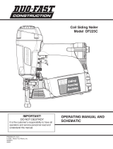
PARTS LEGEND
T250S-F16P Part #515500
45 515545 1 Spring Pin
46 515546 1 Upper Plate
47 515547 1 Nail Guide
48 515548 2 Hex. Soc.Hd. Bolt
49 515549 1 Belt Hook
50 515550 1 Trigger Valve Assembly
51 617780 1 Spring
52 515552 1 Selectable Trigger
53 515553 1 Magazine (Right)
54 515554 1 Pusher
55 515555 1 Spring
56 515556 1 Spring Pin
57 515557 1 Pusher Seat Assembly
58 515558 1 Roll Spring
59 515559 1 Magazine (Left)
60 515560 2 Lock Nut
61 515561 1 Flat self-tapping Bolt
62 515562 1 Pusher Upper seat
63 515563 1 Push Button
64 515564 1 Spring
65 515565 2 UM. HD. Bolt
66 515566 1 Lower Plate
67 515567 2 Logo Label
68
69 515569 1 Model Label
70 515570 1 Magazine Assembly
71 515571 1 Lock Label
3
4 515504 1 Top Cap Ring
5 515505 1 Hex. Soc. Hd. Bolt
6 515506 1 Spacer
7 515507 1 Piston Stopper
8 515508 1 Spring
9 515509 1 Head Valve Assembly
10 515510 1 O-Ring
11 515511 O-Ring
12 515512 1 Seal
13
14 515514 1 Collar
15 515515 1 Driver Blade Assembly
16 515516 1 Wear-Ring
17 515517 1 O-Ring
18 515518 1 Cylinder
19 515519 1 O-Ring
20 515520 1 Cylinder-Ring
21 515521 1 O-Ring
22 515522 1 O-Ring
23 515523 1 Bumper
24 515524 1 Housing
25 515525 1 End Cap Seal
26 515526 1 End Cap
27 615920 1 Air Plug
28 515528 4 Spring Pin
29 515529 1 Bumper Seal
30 515530 1 Depth of Drive A
31 515531 1 WCE Connector
32 403713 1 E-Ring
33 515533 1 Latch Spring Assembly
34 515534 1 Latch
35 515535 1 Spring Pin
36 515536 1 Door
37 515537 1 Spring Pin
38 515538 1 WCE
39 515539 2 Hex. Soc.Hd. Bolt
40 515540 1 Set Plate
41 515541 1 Nose
42 617456 1 Spring
43 515543 1 Lock-out Lever
44 515544 1 Spring Pin
* Denotes Normal Wear Items.
** Make sure Warning Label (515568) is properly affixed.
Replace if necessary.
DO NOT EXCEED MAXIMUM
RECOMMENDED AIR PRESSURE
60
0
120
60
0
120
Always wear hearing protection and eye protection devices,
including side shields when operating or working in the vicinity
of a tool.
Operate the tool using only the recommended air pressure. Do
not exceed the maximum air pressure marked on the tool. Be
sure the air pressure gauge is operating properly and check it
at least twice a day.
SAFETY INSTRUCTIONS
WEAR EYE AND HEARING PROTECTION
10
Never use any bottled air or gases such as
oxygen to operate the tool since they could cause
the tool to explode.
*
*
*
*
*
*
*
*
*
*
*
**
1 515501 7 Hex. Soc. Hd. Bolt
2 515502 1 Cap
515503 1 O-Ring
2
515513 1 Top Cap Seal
515568 1 Warning Label
*
*
*
*
*
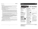
AIR CONSUMPTION CHART
AIR CONSUMPTION-CFM FASTENER
AIR PRESSURE-PSIG
.040
.035
.020
.025
.030
120
.010
.015
11010090807060
.034
.

WARNING
All parts must be periodically inspected and
replaced if worn or broken.
Failure to do this can
affect the toolʼs operation and present a safety
hazard.
T250S-F16P
515500
11

P
Safety Glasses
382104 .oN traP
raelC
ACCESSORIES
An Illinois Tool Works Company
155 Harlem Avenue
Glenview, IL 60025
© 2017, Illinois Tool Works, Inc.
12
/