Page is loading ...

1
PRE-ASSEMBLY INSPECTION
All parts should be examined for any damage during the
shipping and handling process. Measurements should be taken
to ensure parts meet application mounting requirements. All
parts must be clean and free of any foreign material before
attempting assembly.
NOTE: IEB electric brakes are power on units (brake engages
when power is on). IEB brakes are preburnished at the factory
and do not require break-in operation. IEB brakes are designed
with DYNAGAP™ self-adjusting feature that will automatically
compensate for friction surface wear. Armature air gaps should
range from 0.030” to 0.050”, which have been pre-set at the
factory. Do not oil or grease friction surfaces.
IEB brakes may be mounted on either a thru shaft or motor with
shaft extension.
DODGE IEB Series brakes meet UL508 standards and are also
CSA (Canadian Standards Association) approved.
INSTALLATION: Thru Shaft Mounting
WARNING: To ensure that drive is not unexpectedly started,
turn off and lock out or tag power source before proceeding.
Failure to observe these precautions could result in bodily
injury.
1. The lEB-375 is furnished as straight bored brake only and
mounts directly on a thru shaft. Install key and slide brake into
position. Tighten the two setscrews to 78 in-lbs.
All other IEB brakes are mounted using TAPER-LOCK®
bushings. Pre-position TAPER-LOCK bushing in armature hub
before sliding onto shaft. Do not completely draw-in TAPER-
LOCK bushing.
2. Install reaction arm on brake housing, (see Installing Brake
Reaction Arm section).
Table 1 - Brake/Bushing Compatibility
Brake Size TAPER-LOCK Bushing Size Used
IEB-375 None Used – Bored-to-Size
IEB-475 #1008 – 1" Max. Bore
IEB-650 #1310 – 1-7/16" Max. Bore
IEB-825 #1615 – 1-11/16" Max. Bore
WARNING: Because of the possible danger to person(s) or property from
accidents which may result from the improper use of products, it is
important that correct procedures be followed. Products must be used
in accordance with the engineering information specified in the catalog.
Proper installation, maintenance and operation procedures must be
observed. The instructions in the instruction manuals must be followed.
Inspections should be made as necessary to assure safe operation
under prevailing conditions. Proper guards and other suitable safety
devices or procedures, as may be desirable, or as may be specified in
safety codes should be provided, and are neither provided by Baldor
Electric Company, nor are the responsibility of Baldor Electric Company.
This unit and its associated equipment must be installed, adjusted and
maintained by qualified personnel who are familiar with the construction
and operation of all equipment in the system and the potential hazards
involved. When risks to persons or property may be involved, a holding
device must be an integral part of the driven equipment beyond the
speed reducer output shaft.
Instruction Manual
DODGE IEB Series Electric Brakes
These instructions must be read thoroughly before installation or operation.
Table 2 - Electrical Coil Data
IEB-375
Voltage—DC 90 24 6
Resistance @ 20ºC—Ohms 458 30 1.97
Current—Amperes .196 .800 3.05
Watts 17.6 19.2 18.3
Coil Build-up—milliseconds 35 36 32
Coil Decay—milliseconds 6 6 6
IEB-475
Voltage—DC 90 24 6
Resistance @ 20ºC—Ohms 476 32.3 2.06
Current—Amperes .189 .743 2.92
Watts 17.0 17.8 17.5
Coil Build-up—milliseconds 96 97 91
Coil Decay—milliseconds 16 16 16
IEB-650
Voltage—DC 90 24 6
Resistance @ 20ºC—Ohms 250 16.2 .910
Current—Amperes .36 1.48 6.63
Watts 32 36 39
Coil Build-up—milliseconds 115 112 110
Coil Decay—milliseconds 20 20 20
IEB-825
Voltage—DC 90 24 6
Resistance @ 20ºC—Ohms 220 14.5 1.10
Current—Amperes .40 1.65 5.4
Watts 36 40 32
Coil Build-up—milliseconds 175 172 170
Coil Decay—milliseconds 85 83 80
NOTE: Coil build-up is to 80% of Rated Current. Coil Decay Time is with DODGE
Power Supply. Due to variations in other manufacturers’ supplies, the delay time
may vary.
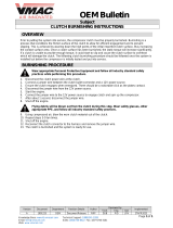
INSTALLATION: Motor Mounting
Mounting the IEB brake onto a motor shaft may require an
optional shaft extension.
1. Mount a standard sheave, sprocket or pulley on the usable
length of the brake adapter (see Table 5 for brake adapter
dimensions). The drive component can be mounted using
TAPER-LOCK® or Q.D. Bushings.
2. Insert the proper TAPER-LOCK® bushing into the IEB Brake.
NOTE: IEB-375 is straight bore mounted.
3. Finger tighten setscrews (loosely) into bushing.
4. Mount IEB brake on end of motor adapter. Tighten setscrews
in bushing (or hub for IEB 375) per recommended tightening
torques.
5. Slide complete assembly (brake, drive component and
adapter) onto motor shaft extension and tighten setscrews.
(Be sure key is installed in keyway).
6. Position V-belts, chains, etc. on drive component.
7. Fasten reaction arm on brake housing. See Installation: Brake
Reaction Arm.
Figure 1

2
8. Be sure all parts are securely fastened before attempting to
operate this unit.
ELECTRICAL CONNECTIONS
DANGER: The user is responsible for conforming with the
National Electrical Code and all other applicable local codes.
Wiring practices, grounding, disconnects and overcurrent
protection are of particular importance. Failure to observe
these precautions could result in severe bodily injury or loss
of life.
DODGE IEB Series brakes operate on standard DC voltage coils.
To operate the brake with alternating current, an AC to DC power
supply is required. Do not connect AC voltage directly to coil
leads. Wire the two leads to the power supply. DODGE power
supplies are available with a wiring diagram showing proper
electrical connections.
INSTALLATION: Brake Reaction Arm
The reaction arm acts as a restraining mechanism when the
brake is applied. The IEB brake operates best when used with
the supplied reaction arm. The ball joint ensures proper housing
reactions. If an alternate reaction arm is being used, be sure
to use a ball-type joint that pivots to allow the holding reaction
without binding the magnet eld. The threaded rod provided
can be cut to any length desired. The reaction arm should be
mounted so the arm is at a right angle and in tension rather than
compression.
MAINTENANCE GUIDE
WARNING: To ensure that drive is not unexpectedly started,
turn off and lock out or tag power source before proceeding.
Failure to observe these precautions could result in bodily
injury.
TASK PROCEDURE
Armature
Replacement
Replacing the
Brake Magnet
TROUBLESHOOTING GUIDE
DANGER: Subsequent steps require rotating parts and/or
electrical circuits to be exposed. Stay clear if unit must be
running or disconnect and lockout or tag power source if
contact must be made. Failure to observe these precautions
could result in severe bodily injury or loss of life.
SYMPTOM/CAUSE SOLUTION
Armature rubbing,
periodic noise to
constant rubbing.
No engagement
when coil is
energized.
(1) Coil may be
shorted to ground.
(2) Armature air
gap is too large.
Figure 2
Figure 3
Remove worn armature by rotating and
gradually prying the armature off the splined
hub. (On sizes 650 and 825 this will involve
rst removing the retaining ring on the
outside diameter of the spline hub.) You
must overcome gripping force of the grip
ring, therefore, the use of a small puller
simplies this task. You must overcome this
same gripping force when installing the new
armature. Care must be taken not to bend
armature washers during assembly. A soft
mallet and/or block of wood can be used to
start the armature onto the spline. With the
nned armature surface facing away from
the friction surface, push brake armature
ush against brake magnet friction surface
and release. The DYNAGAP™ feature will
automatically set air gap. Reinstall retaining
ring when nished.
MOTOR ADAPTER FOR
SINGLE SHAFT MOTORS
IEB SERIES BRAKE
MOUNTED ON DOUBLE
SHAFTED MOTOR
REACTION ARM MAY BE MOUNTED
IN ANY DIRECTION
CLOCKWISE ROTATION
DIRECTION
OF BELT
PULL
THEN POSITION
REACTION ARM &
TAB IN LOCATION A
LOC.
A
DIRECTION OF
BELT PULL
THEN POSITION
REACTION ARM &
TAB IN LOCATION B
LOC.
B
LOC.
A
COUNTERCLOCKWISE ROTATION
LOC.
B
DIRECTION OF
BELT PULL
THEN POSITION
REACTION
ARM & TAB IN
LOCATION A
DIRECTION
OF BELT PULL
THEN
POSITION
REACTION
ARM & TAB
IN LOCATION B
IEB SERIES BRAKE
VIEWED FROM ARMATURE
Remove brake from shaft. Remove armature
using Armature replacement procedure.
Press splined hub out of unit for use with
new brake magnet. A new brake magnet
assembly consists of a brake magnet
(including friction material) and ball bearing.
Using the splined hub out of old unit, press
into new brake magnet assembly. Important:
Ensure inner race of ball bearing is properly
supported to avoid damage to the bearing.
After replacing the snap ring, reinstall the
armature again using Armature replacement
procedure.
Disconnect power to motor. Adjust armature
position using a screwdriver to pry the
armature away (.060” to .090”) from friction
surface on which it is rubbing. Energize coil.
Using even pressure, push armature toward
friction surface until it is fully engaged. It
should pull in by itself when it gets close
enough. Remove pressure and de-energize
coil. The DYNA-GAP™ self-adjusting feature
will automatically maintain proper air gap
(.030” to .050”).
(1) Check coil resistance as follows:
Disconnect power to motor. Connect
ohmmeter to two brake leads. Check value
with Table 2 Electrical Coil Data. If OK,
proceed to solution for checking armature air
gap. If not OK, indicates some electrical
problem with coil. Proceed to procedure for
replacing brake magnet in the Maintenance
Guide.
(2) Disconnect power to motor. Energize
coil. Using even pressure, push armature
toward friction material surface until armature
engages fully. If armature still does not
engage properly, see Armature rubbing.

3
Excessive overlap.
Unit will not cycle
repeatedly.
Rapid wear or short
life. Brake may be
cycling too rapidly
and/or operating at
high temperatures
(component
selection may need
review). The unit may
be operating in a
harsh environment.
Actuation times may
need adjustment.
CAUTION: Only personnel familiar with wear patterns and the
possible effect on the operation of the product’s performance
should adjust the potentiometer setting.
NOTE: Normal wear conditions will result in grooves appearing
on the friction surfaces. Machining away these grooves can result
in premature failure of the unit.
Loss of torque.
Improper input
voltage can cause
complete loss of
torque. Brake may
be nearing the end
of its normal life or
friction surface may
be contaminated
with grease/oil.
Customer switch should be on DC side of
rectier (power supply). A counter or timer
mechanism may include a time constant
circuit or diode which may create overlap.
Check components.
(1) Rapid Cycling: Fast, repetitive cycling
will result in more rapid wear and higher
temperatures. High temperatures will also
accelerate wear rates. Ensure the unit is
being ventilated for maximum cooling to
maximize life.
(2) Exposure to harsh environments such
as on machinery that produces abrasive
dust or grit may shorten life of unit. In
these types of environments, an effort
should be made to shield the brake from
abrasive materials.
(3) Minor adjustments to the actuation time
can prevent premature failure of brake.
The control potentiometer, if provided, can
be adjusted to a lower setting to extend
actuation time, which can result in a longer
operating life.
If a complete loss of torque occurs,
initially check the input voltage to the
brake magnet as follows: Connect a DC
voltmeter with proper range across brake
magnet terminals. With power to the
coil and potentiometer turned to highest
setting, voltage should read within 10%
of unit’s rating. As the potentiometer knob
is adjusted counterclockwise (lower), the
voltage should drop. If these checks prove
proper voltages are being provided, then
mechanical components of the unit should
be checked to ensure the unit has not
been damaged or improperly installed. A
slight loss in torque may become evident
as the brake nears the end of its normal
life. Grease or oil contamination can result
in a substantial loss of torque. If the brake
is positioned near any machinery which
requires frequent lubrication, care must
be taken to avoid grease or oil contacting
friction surfaces. Should oil or grease reach
the friction area, immediately clean the
friction surfaces and general area with a
cloth dampened with a degreaser. Do not
drench or soak the friction material.
Continued loss of torque will result if
friction material is completely contaminated
with oil or grease. Heat developed at the
friction surface will cause the oil to bleed to
the surface, resulting in torque loss. In this
case, the friction surfaces need replaced.
BURNISHING PROCEDURE
For consistent engagement and full rated torque it is necessary to
burnish the brake.
Burnishing is a wearing-in or mating process to ensure the
highest possible output torques will be obtained from the brake.
NOTE: Burnishing is an important maintenance step. Running
the unit without an initial burnishing break-in period may cause
the equipment to operate erratically. Full rated torque will not be
developed until friction surfaces develop full contact.
1. If possible, burnish units in their nal application or location to
ensure alignment of the mated parts.
2. If units cannot be burnished in their nal application, mount
units in a test stand observing concentricity, alignment and air
gaps.
NOTE: If burnishing capability is not practical, cycle the brake
(several hundred engagements may be necessary) to wear unit in
and allow torque to increase.
3. Using a ltered DC power supply, energize unit at 100% of
rated coil voltage for 5 seconds maximum (this assures proper
armature engagement against magnet), then reduce voltage to
30-40% of rated coil voltage.
4. Rotate the brake armature at suggested RPM (Table 3) while
holding the brake magnet stationary to obtain a forced slip
while the unit is energized.
Table 3 - Recommended Burnishing RPM
Unit Size Burnishing RPM +10%
IEB-375 40
IEB-475 30
IEB-650 20
IEB-825 20
5. De-energize the unit after a 2-minute forced slip.
WARNING: To ensure that drive is not unexpectedly started,
turn off and lock out or tag power source before proceeding.
Failure to observe these precautions could result in bodily
injury.
6. Measure static (or break away) torque of the unit with both
friction members of the brake stationary, at rated voltage.
7. Static torque should be at the catalog rating (Table 4). If unit
does not measure catalog rating, repeat step 4 after a cool
down period of 5 minutes, until the unit comes up to the rated
torque.
Table 4 - Standard Static Torques
Unit Size Static Torque Ft-Lbs.
IEB-375 22
IEB-475 34
IEB-650 100
IEB-825 175
NOTES:
If clutch is required to decelerate a large inertia load, the normal
slip that will occur when the load is engaged is frequently
sufcient to cause the unit to become burnished. DODGE
clutches typically will produce 50-90% of their rated torque
“out-of-box” without burnishing. Customer should determine if
“out-of-box” torques are adequate for application as torque will
automatically improve with normal cycling (especially on high
speed, high inertia load applications).
Do not prolong burnish beyond 2-minutes. Long burnish time will
cause excessive heat build-up at friction faces resulting in poor
performance.
Care must be taken to prevent contamination of the friction faces
with oil or dirt particles during the burnishing process.

World Headquarters
P.O. Box 2400, Fort Smith, AR 72902-2400 U.S.A., Ph: (1) 479.646.4711, Fax (1) 479.648.5792, International Fax (1) 479.648.5895
Dodge Product Support
6040 Ponders Court, Greenville, SC 29615-4617 U.S.A., Ph: (1) 864.297.4800, Fax: (1) 864.281.2433
www.baldor.com
© Baldor Electric Company
MN4014 (Replaces 499753)
All Rights Reserved. Printed in USA.
5/10 PRINTSHOP 1000
*4014-0410*
Table 5 - IEB Adapter Dimensions (inches)
Size
Adapter
P/N
A
A
Keyway
B
B
Keyway
C
C
Keyway
Bushing
Size
Taper-Lock
Bushing
P/N
for Brake
Bushing
P/N
D
E F G H I
IEB-375
032300 5/8 3/16 x 3/32 7/8 3/16 x 3/32 5/8 3/16 x 3/32 none none
4.391
4.359
2
.516
.484
2
1/4-20
UNC
1/4-20
032301 7/8 3/16 x 3/32 1-1/4 1/4 x 1/8 5/8 3/16 x 3/32 none none
4.578
4.742
2-1/4
.516
.484
2-1/4
1/4-20
UNC
1/4-20
IEB-475 032302 1-1/8 1/4 x 1/8 1-5/8 3/8 x 3/16 1 1/4 x 1/8 1008 119184
4.516
4.484
2-3/4
.641
.609
2-3/4
1/2-13
UNC
3/8-16
IEB-650
&
IEB-825
032303 1-3/8 5/16 x 5/32 2 1/2 x 1/4 1-3/8 5/16 x 5/32 1310 119404
5.547
5.515
3-3/8
.641
.609
3-3/8
1/2-13
UNC
3/8-16
032304 1-5/8 3/8 x 3/16 2-1/4 1/2 x 1/4 1-3/8 5/16 x 5/32
1310
1615
119404
119054
6.172
6.140
4
.641
.609
4
1/2-13
UNC
3/8-16
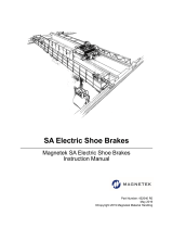
Figure 4 - IEB Cross Section
Figure 5 - Armature Detail
BRAKE
ARMATURE
SPLINED
HUB
SNAP RING
(IEB-650 &
IEB-825 ONLY)
BRAKE
FIELD
CONDUIT BOX
SEE ARMATURE
DETAIL
TAPER-LOCK BORE
(IEB-375 HAS
STRAIGHT BORE)
BALL
BEARING
BRAKE
FIELD
ARMATURE
SPLINE
SNAP RING
ARMATURE WASHER
DYNA-GAP
MECHANISM
WAVE SPRING
GRIP RING
ARMATURE FAN
ARMATURE
BRAKE FRICTION MATERIAL
BRAKE AIR GAP = .040
H
E
B
C
G
D
A
F
I
(THREADED REMOVAL HOLE)
(USEABLE
MOUNTING LENGTH)
Figure 6 - IEB Adapters
/