Miller MB100177U Owner's manual
- Category
- Welding System
- Type
- Owner's manual
This manual is also suitable for

Visit our website at
www.MillerWelds.com
Description
OM-2807 191 256B
2011−02
Portable Load Bank To Load Test AC
Or DC Welding Power Sources
LBP-350

Miller Electric manufactures a full line
of welders and welding related equipment.
For information on other quality Miller
products, contact your local Miller distributor to receive the latest full
line catalog or individual specification sheets. To locate your nearest
distributor or service agency call 1-800-4-A-Miller, or visit us at
www.MillerWelds.com on the web.
Thank you and congratulations on choosing Miller. Now you can get
the job done and get it done right. We know you don’t have time to do
it any other way.
That’s why when Niels Miller first started building arc welders in 1929,
he made sure his products offered long-lasting value and superior
quality. Like you, his customers couldn’t afford anything less. Miller
products had to be more than the best they could be. They had to be the
best you could buy.
Today, the people that build and sell Miller products continue the
tradition. They’re just as committed to providing equipment and service
that meets the high standards of quality and value established in 1929.
This Owner’s Manual is designed to help you get the most out of your
Miller products. Please take time to read the Safety precautions. They
will help you protect yourself against potential hazards on the worksite.
We’ve made installation and operation quick
and easy. With Miller you can count on years
of reliable service with proper maintenance.
And if for some reason the unit needs repair,
there’s a Troubleshooting section that will
help you figure out what the problem is. The
parts list will then help you to decide the
exact part you may need to fix the problem.
Warranty and service information for your
particular model are also provided.
Miller is the first welding
equipment manufacturer in
the U.S.A. to be registered to
the ISO 9001 Quality System
Standard.
Working as hard as you do
− every power source from
Miller is backed by the most
hassle-free warranty in the
business.
From Miller to You
Mil_Thank 2009−09
Page is loading ...
Page is loading ...

OM-2807 Page 1
SECTION 1 − SAFETY PRECAUTIONS - READ BEFORE USING
som 2011−01
7
Protect yourself and others from injury — read and follow these precautions.
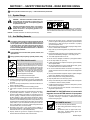
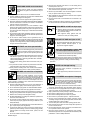
1-1. Symbol Usage
DANGER! − Indicates a hazardous situation which, if
not avoided, will result in death or serious injury. The
possible hazards are shown in the adjoining symbols
or explained in the text.
Indicates a hazardous situation which, if not avoided,
could result in death or serious injury. The possible
hazards are shown in the adjoining symbols or ex-
plained in the text.
NOTICE − Indicates statements not related to personal injury.
Indicates special instructions.
This group of symbols means Warning! Watch Out! ELECTRIC
SHOCK, MOVING PARTS, and HOT PARTS hazards. Consult sym-
bols and related instructions below for necessary actions to avoid the
hazards.
1-2. Arc Welding Hazards
The symbols shown below are used throughout this manual
to call attention to and identify possible hazards. When you
see the symbol, watch out, and follow the related instructions
to avoid the hazard. The safety information given below is
only a summary of the more complete safety information
found in the Safety Standards listed in Section 1-5. Read and
follow all Safety Standards.
Only qualified persons should install, operate, maintain, and
repair this unit.
During operation, keep everybody, especially children, away.
ELECTRIC SHOCK can kill.
Touching live electrical parts can cause fatal shocks
or severe burns. The electrode and work circuit is
electrically live whenever the output is on. The input
power circuit and machine internal circuits are also
live when power is on. In semiautomatic or automatic
wire welding, the wire, wire reel, drive roll housing,
and all metal parts touching the welding wire are
electrically live. Incorrectly installed or improperly
grounded equipment is a hazard.
Do not touch live electrical parts.
Wear dry, hole-free insulating gloves and body protection.
Insulate yourself from work and ground using dry insulating mats
or covers big enough to prevent any physical contact with the work
or ground.
Do not use AC output in damp areas, if movement is confined, or if
there is a danger of falling.
Use AC output ONLY if required for the welding process.
If AC output is required, use remote output control if present on
unit.
Additional safety precautions are required when any of the follow-
ing electrically hazardous conditions are present: in damp
locations or while wearing wet clothing; on metal structures such
as floors, gratings, or scaffolds; when in cramped positions such
as sitting, kneeling, or lying; or when there is a high risk of unavoid-
able or accidental contact with the workpiece or ground. For these
conditions, use the following equipment in order presented: 1) a
semiautomatic DC constant voltage (wire) welder, 2) a DC manual
(stick) welder, or 3) an AC welder with reduced open-circuit volt-
age. In most situations, use of a DC, constant voltage wire welder
is recommended. And, do not work alone!
Disconnect input power or stop engine before installing or
servicing this equipment. Lockout/tagout input power according to
OSHA 29 CFR 1910.147 (see Safety Standards).
Properly install and ground this equipment according to its
Owner’s Manual and national, state, and local codes.
Always verify the supply ground − check and be sure that input
power cord ground wire is properly connected to ground terminal in
disconnect box or that cord plug is connected to a properly
grounded receptacle outlet.
When making input connections, attach proper grounding conduc-
tor first − double-check connections.
Keep cords dry, free of oil and grease, and protected from hot metal
and sparks.
Frequently inspect input power cord for damage or bare wiring −
replace cord immediately if damaged − bare wiring can kill.
Turn off all equipment when not in use.
Do not use worn, damaged, undersized, or poorly spliced cables.
Do not drape cables over your body.
If earth grounding of the workpiece is required, ground it directly
with a separate cable.
Do not touch electrode if you are in contact with the work, ground,
or another electrode from a different machine.
Do not touch electrode holders connected to two welding ma-
chines at the same time since double open-circuit voltage will be
present.
Use only well-maintained equipment. Repair or replace damaged
parts at once. Maintain unit according to manual.
Wear a safety harness if working above floor level.
Keep all panels and covers securely in place.
Clamp work cable with good metal-to-metal contact to workpiece
or worktable as near the weld as practical.
Insulate work clamp when not connected to workpiece to prevent
contact with any metal object.
Do not connect more than one electrode or work cable to any
single weld output terminal.
SIGNIFICANT DC VOLTAGE exists in inverter weld-
ing power sources AFTER removal of input power.
Turn Off inverter, disconnect input power, and discharge input
capacitors according to instructions in Maintenance Section
before touching any parts.
HOT PARTS can burn.
Do not touch hot parts bare handed.
Allow cooling period before working on equip-
ment.
To handle hot parts, use proper tools and/or
wear heavy, insulated welding gloves and
clothing to prevent burns.

OM-2807 Page 2
Welding produces fumes and gases. Breathing
these fumes and gases can be hazardous to your
health.
FUMES AND GASES can be hazardous.
Keep your head out of the fumes. Do not breathe the fumes.
If inside, ventilate the area and/or use local forced ventilation at the
arc to remove welding fumes and gases.
If ventilation is poor, wear an approved air-supplied respirator.
Read and understand the Material Safety Data Sheets (MSDSs)
and the manufacturer’s instructions for metals, consumables,
coatings, cleaners, and degreasers.
Work in a confined space only if it is well ventilated, or while
wearing an air-supplied respirator. Always have a trained watch-
person nearby. Welding fumes and gases can displace air and
lower the oxygen level causing injury or death. Be sure the breath-
ing air is safe.
Do not weld in locations near degreasing, cleaning, or spraying op-
erations. The heat and rays of the arc can react with vapors to form
highly toxic and irritating gases.
Do not weld on coated metals, such as galvanized, lead, or
cadmium plated steel, unless the coating is removed from the weld
area, the area is well ventilated, and while wearing an air-supplied
respirator. The coatings and any metals containing these elements
can give off toxic fumes if welded.
Arc rays from the welding process produce intense
visible and invisible (ultraviolet and infrared) rays
that can burn eyes and skin. Sparks fly off from the
weld.
Wear an approved welding helmet fitted with a proper shade of
filter lenses to protect your face and eyes from arc rays and
sparks when welding or watching (see ANSI Z49.1 and Z87.1
listed in Safety Standards).
Wear approved safety glasses with side shields under your
helmet.
Use protective screens or barriers to protect others from flash,
glare and sparks; warn others not to watch the arc.
Wear protective clothing made from durable, flame-resistant
material (leather, heavy cotton, or wool) and foot protection.
ARC RAYS can burn eyes and skin.
Welding on closed containers, such as tanks,
drums, or pipes, can cause them to blow up. Sparks
can fly off from the welding arc. The flying sparks, hot
workpiece, and hot equipment can cause fires and
burns. Accidental contact of electrode to metal objects can cause
sparks, explosion, overheating, or fire. Check and be sure the area is
safe before doing any welding.
WELDING can cause fire or explosion.
Remove all flammables within 35 ft (10.7 m) of the welding arc. If
this is not possible, tightly cover them with approved covers.
Do not weld where flying sparks can strike flammable material.
Protect yourself and others from flying sparks and hot metal.
Be alert that welding sparks and hot materials from welding can
easily go through small cracks and openings to adjacent areas.
Watch for fire, and keep a fire extinguisher nearby.
Be aware that welding on a ceiling, floor, bulkhead, or partition can
cause fire on the hidden side.
Do not weld on closed containers such as tanks, drums, or pipes,
unless they are properly prepared according to AWS F4.1 (see
Safety Standards).
Do not weld where the atmosphere may contain flammable dust,
gas, or liquid vapors (such as gasoline).
Connect work cable to the work as close to the welding area as
practical to prevent welding current from traveling long, possibly
unknown paths and causing electric shock, sparks, and fire
hazards.
Do not use welder to thaw frozen pipes.
Remove stick electrode from holder or cut off welding wire at
contact tip when not in use.
Wear oil-free protective garments such as leather gloves, heavy
shirt, cuffless trousers, high shoes, and a cap.
Remove any combustibles, such as a butane lighter or matches,
from your person before doing any welding.
After completion of work, inspect area to ensure it is free of sparks,
glowing embers, and flames.
Use only correct fuses or circuit breakers. Do not oversize or by-
pass them.
Follow requirements in OSHA 1910.252 (a) (2) (iv) and NFPA 51B
for hot work and have a fire watcher and extinguisher nearby.
FLYING METAL or DIRT can injure eyes.
Welding, chipping, wire brushing, and grinding
cause sparks and flying metal. As welds cool,
they can throw off slag.
Wear approved safety glasses with side
shields even under your welding helmet.
BUILDUP OF GAS can injure or kill.
Shut off compressed gas supply when not in use.
Always ventilate confined spaces or use
approved air-supplied respirator.
ELECTRIC AND MAGNETIC FIELDS (EMF
)
can affect Implanted Medical Devices.
Wearers of Pacemakers and other Implanted
Medical Devices should keep away.
Implanted Medical Device wearers should consult their doctor
and the device manufacturer before going near arc welding, spot
welding, gouging, plasma arc cutting, or induction heating
operations.
NOISE can damage hearing.
Noise from some processes or equipment can
damage hearing.
Wear approved ear protection if noise level is
high.
Compressed gas cylinders contain gas under high
pressure. If damaged, a cylinder can explode. Since
gas cylinders are normally part of the welding
process, be sure to treat them carefully.
CYLINDERS can explode if damaged.
Protect compressed gas cylinders from excessive heat, mechani-
cal shocks, physical damage, slag, open flames, sparks, and arcs.
Install cylinders in an upright position by securing to a stationary
support or cylinder rack to prevent falling or tipping.
Keep cylinders away from any welding or other electrical circuits.
Never drape a welding torch over a gas cylinder.
Never allow a welding electrode to touch any cylinder.
Never weld on a pressurized cylinder − explosion will result.
Use only correct compressed gas cylinders, regulators, hoses,
and fittings designed for the specific application; maintain them
and associated parts in good condition.
Turn face away from valve outlet when opening cylinder valve.
Keep protective cap in place over valve except when cylinder is in
use or connected for use.
Use the right equipment, correct procedures, and sufficient num-
ber of persons to lift and move cylinders.
Read and follow instructions on compressed gas cylinders,
associated equipment, and Compressed Gas Association (CGA)
publication P-1 listed in Safety Standards.

OM-2807 Page 3
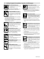
1-3. Additional Symbols For Installation, Operation, And Maintenance
FIRE OR EXPLOSION hazard.
Do not install or place unit on, over, or near
combustible surfaces.
Do not install unit near flammables.
Do not overload building wiring − be sure power supply system is
properly sized, rated, and protected to handle this unit.
FALLING EQUIPMENT can injure.
Use lifting eye to lift unit only, NOT running
gear, gas cylinders, or any other accessories.
Use equipment of adequate capacity to lift and
support unit.
If using lift forks to move unit, be sure forks are long enough to
extend beyond opposite side of unit.
Keep equipment (cables and cords) away from moving vehicles
when working from an aerial location.
Follow the guidelines in the Applications Manual for the Revised
NIOSH Lifting Equation (Publication No. 94−110) when manu-
ally lifting heavy parts or equipment.
OVERUSE can cause OVERHEATING
Allow cooling period; follow rated duty cycle.
Reduce current or reduce duty cycle before
starting to weld again.
Do not block or filter airflow to unit.
FLYING SPARKS can injure.
Wear a face shield to protect eyes and face.
Shape tungsten electrode only on grinder with
proper guards in a safe location wearing proper
face, hand, and body protection.
Sparks can cause fires — keep flammables away.
STATIC (ESD) can damage PC boards.
Put on grounded wrist strap BEFORE handling
boards or parts.
Use proper static-proof bags and boxes to
store, move, or ship PC boards.
MOVING PARTS can injure.
Keep away from moving parts.
Keep away from pinch points such as drive
rolls.
WELDING WIRE can injure.
Do not press gun trigger until instructed to do
so.
Do not point gun toward any part of the body,
other people, or any metal when threading
welding wire.
MOVING PARTS can injure.
Keep away from moving parts such as fans.
Keep all doors, panels, covers, and guards
closed and securely in place.
Have only qualified persons remove doors, panels, covers, or
guards for maintenance and troubleshooting as necessary.
Reinstall doors, panels, covers, or guards when maintenance is
finished and before reconnecting input power.
READ INSTRUCTIONS.
Read and follow all labels and the Owner’s
Manual carefully before installing, operating, or
servicing unit. Read the safety information at
the beginning of the manual and in each
section.
Use only genuine replacement parts from the manufacturer.
Perform maintenance and service according to the Owner’s
Manuals, industry standards, and national, state, and local
codes.
H.F. RADIATION can cause interference.
High-frequency (H.F.) can interfere with radio
navigation, safety services, computers, and
communications equipment.
Have only qualified persons familiar with
electronic equipment perform this installation.
The user is responsible for having a qualified electrician prompt-
ly correct any interference problem resulting from the installa-
tion.
If notified by the FCC about interference, stop using the
equipment at once.
Have the installation regularly checked and maintained.
Keep high-frequency source doors and panels tightly shut, keep
spark gaps at correct setting, and use grounding and shielding to
minimize the possibility of interference.
ARC WELDING can cause interference.
Electromagnetic energy can interfere with
sensitive electronic equipment such as
computers and computer-driven equipment
such as robots.
Be sure all equipment in the welding area is
electromagnetically compatible.
To reduce possible interference, keep weld cables as short as
possible, close together, and down low, such as on the floor.
Locate welding operation 100 meters from any sensitive elec-
tronic equipment.
Be sure this welding machine is installed and grounded
according to this manual.
If interference still occurs, the user must take extra measures
such as moving the welding machine, using shielded cables,
using line filters, or shielding the work area.

OM-2807 Page 4
1-4. California Proposition 65 Warnings
Welding or cutting equipment produces fumes or gases
which contain chemicals known to the State of California to
cause birth defects and, in some cases, cancer. (California
Health & Safety Code Section 25249.5 et seq.)
Battery posts, terminals and related accessories contain lead
and lead compounds, chemicals known to the State of
California to cause cancer and birth defects or other
reproductive harm. Wash hands after handling.
This product contains chemicals, including lead, known to
the state of California to cause cancer, birth defects, or other
reproductive harm. Wash hands after use.
For Gasoline Engines:
Engine exhaust contains chemicals known to the State of
California to cause cancer, birth defects, or other reproduc-
tive harm.
For Diesel Engines:
Diesel engine exhaust and some of its constituents are
known to the State of California to cause cancer, birth
defects, and other reproductive harm.
1-5. Principal Safety Standards
Safety in Welding, Cutting, and Allied Processes, ANSI Standard Z49.1,
from Global Engineering Documents (phone: 1-877-413-5184, website:
www.global.ihs.com).
Safe Practices for the Preparation of Containers and Piping for Welding
and Cutting, American Welding Society Standard AWS F4.1, from Glob-
al Engineering Documents (phone: 1-877-413-5184, website:
www.global.ihs.com).
National Electrical Code, NFPA Standard 70, from National Fire Protec-
tion Association, Quincy, MA 02269 (phone: 1-800-344-3555, website:
www.nfpa.org and www. sparky.org).
Safe Handling of Compressed Gases in Cylinders, CGA Pamphlet P-1,
from Compressed Gas Association, 4221 Walney Road, 5th Floor,
Chantilly, VA 20151 (phone: 703-788-2700, website:www.cganet.com).
Safety in Welding, Cutting, and Allied Processes, CSA Standard
W117.2, from Canadian Standards Association, Standards Sales, 5060
Spectrum Way, Suite 100, Ontario, Canada L4W 5NS (phone:
800-463-6727, website: www.csa-international.org).
Safe Practice For Occupational And Educational Eye And Face Protec-
tion, ANSI Standard Z87.1, from American National Standards Institute,
25 West 43rd Street, New York, NY 10036 (phone: 212-642-4900, web-
site: www.ansi.org).
Standard for Fire Prevention During Welding, Cutting, and Other Hot
Work, NFPA Standard 51B, from National Fire Protection Association,
Quincy, MA 02269 (phone: 1-800-344-3555, website: www.nfpa.org.
OSHA, Occupational Safety and Health Standards for General Indus-
try, Title 29, Code of Federal Regulations (CFR), Part 1910, Subpart Q,
and Part 1926, Subpart J, from U.S. Government Printing Office, Super-
intendent of Documents, P.O. Box 371954, Pittsburgh, PA 15250-7954
(phone: 1-866-512-1800) (there are 10 OSHA Regional Offices—
phone for Region 5, Chicago, is 312-353-2220, website:
www.osha.gov).
U.S. Consumer Product Safety Commission (CPSC), 4330 East West
Highway, Bethesda, MD 20814 (phone: 301-504-7923, website:
www.cpsc.gov).
Applications Manual for the Revised NIOSH Lifting Equation, The Na-
tional Institute for Occupational Safety and Health (NIOSH), 1600
Clifton Rd, Atlanta, GA 30333 (phone: 1-800-232-4636, website:
www.cdc.gov/NIOSH).
1-6. EMF Information
Electric current flowing through any conductor causes localized electric
and magnetic fields (EMF). Welding current creates an EMF field
around the welding circuit and welding equipment. EMF fields may inter-
fere with some medical implants, e.g. pacemakers. Protective
measures for persons wearing medical implants have to be taken. For
example, access restrictions for passers−by or individual risk assess-
ment for welders. All welders should use the following procedures in
order to minimize exposure to EMF fields from the welding circuit:
1. Keep cables close together by twisting or taping them, or using a
cable cover.
2. Do not place your body between welding cables. Arrange cables
to one side and away from the operator.
3. Do not coil or drape cables around your body.
4. Keep head and trunk as far away from the equipment in the
welding circuit as possible.
5. Connect work clamp to workpiece as close to the weld as
possible.
6. Do not work next to, sit or lean on the welding power source.
7. Do not weld whilst carrying the welding power source or wire
feeder.
About Implanted Medical Devices:
Implanted Medical Device wearers should consult their doctor and the
device manufacturer before performing or going near arc welding, spot
welding, gouging, plasma arc cutting, or induction heating operations.
If cleared by your doctor, then following the above procedures is recom-
mended.
Page is loading ...
Page is loading ...
Page is loading ...
Page is loading ...

OM-2807 Page 9
2-5. Principales normes de sécurité
Safety in Welding, Cutting, and Allied Processes, ANSI Standard Z49.1,
de Global Engineering Documents (téléphone : 1-877-413-5184, site
Internet : www.global.ihs.com).
Safe Practices for the Preparation of Containers and Piping for Welding
and Cutting, American Welding Society Standard AWS F4.1, de Global
Engineering Documents (téléphone : 1-877-413-5184, site internet :
www.global.ihs.com).
National Electrical Code, NFPA Standard 70, de National Fire Protec-
tion Association, Quincy, MA 02269 (téléphone : 800-344-3555, site
Internet : www.nfpa.org et www.sparky.org).
Safe Handling of Compressed Gases in Cylinders, CGA Pamphlet P-1,
de Compressed Gas Association, 4221 Walney Road, 5th Floor, Chan-
tilly, VA 20151 (téléphone : 703-788-2700, site Internet :
www.cganet.com).
Safety in Welding, Cutting, and Allied Processes, CSA Standard
W117.2, de Canadian Standards Association, Standards Sales, 5060
Spectrum Way, Suite 100, Ontario, Canada L4W 5NS (téléphone :
800-463-6727, site internet : www.csa-international.org).
Safe Practice For Occupational And Educational Eye And Face Protec-
tion, ANSI Standard Z87.1, de American National Standards Institute,
25 West 43rd Street, New York, NY 10036 (téléphone : 212-642-4900,
site Internet : www.ansi.org).
Standard for Fire Prevention During Welding, Cutting, and Other Hot
Work, NFPA Standard 51B, de National Fire Protection Association,
P.O. Box 9101, Quincy, MA 02269-9101 (téléphone : 617-770-3000,
site Internet : www.nfpa.org).
OSHA, Occupational Safety and Health Standards for General
Industry, Title 29, Code of Federal Regulations (CFR), Part 1910,
Subpart Q, and Part 1926, Subpart J, de U.S. Government Printing
Office, Superintendent of Documents, P.O. Box 371954, Pittsburgh, PA
15250-7954 (téléphone : 1-866-512-1800) (il y a 10 bureaux
régionaux−le téléphone de la région 5, Chicago, est 312-353-2220, site
Internet : www.osha.gov).
U.S. Consumer Product Safety Commission (CPSC), 4330 East West
Highway, Bethesda, MD 20814 (téléphone : 301-504-7923, site inter-
net : www.cpsc.gov).
Applications Manual for the Revised NIOSH Lifting Equation, The
National Institute for Occupational Safety and Health (NIOSH), 1600
Clifton Rd, Atlanta, GA 30333 (télé[hone : 1-800-232-4636, site internet:
www.cdc.gov/NIOSH).
2-6. Informations relatives aux CEM
Le courant électrique qui traverse tout conducteur génère des champs
électromagnétiques (CEM) à certains endroits. Le courant de soudage
crée un CEM autour du circuit et du matériel de soudage. Les CEM
peuvent créer des interférences avec certains implants médicaux
comme des stimulateurs cardiaques. Des mesures de protection pour
les porteurs d’implants médicaux doivent être prises: par exemple, des
restrictions d’accès pour les passants ou une évaluation individuelle
des risques pour les soudeurs. Tous les soudeurs doivent appliquer les
procédures suivantes pour minimiser l’exposition aux CEM provenant
du circuit de soudage:
1. Rassembler les câbles en les torsadant ou en les attachant avec
du ruban adhésif ou avec une housse.
2. Ne pas se tenir au milieu des câbles de soudage. Disposer les
câbles d’un côté et à distance de l’opérateur.
3. Ne pas courber et ne pas entourer les câbles autour de votre
corps.
4. Maintenir la tête et le torse aussi loin que possible du matériel du
circuit de soudage.
5. Connecter la pince sur la pièce aussi près que possible de la
soudure.
6. Ne pas travailler à proximité d’une source de soudage, ni
s’asseoir ou se pencher dessus.
7. Ne pas souder tout en portant la source de soudage ou le
dévidoir.
En ce qui concerne les implants médicaux :
Les porteurs d’implants doivent d’abord consulter leur médecin avant
de s’approcher des opérations de soudage à l’arc, de soudage par
points, de gougeage, du coupage plasma ou de chauffage par induc-
tion. Si le médecin approuve, il est recommandé de suivre les
procédures précédentes.
Page is loading ...

OM-2807 Page 11
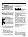
SECTION 3 − INTRODUCTION
3-1. Specifications
Specification Description
Type Of Input Power Single-Phase 115 Volts AC, 0.6 Amperes, 50/60 Hertz
Input Power Cord With Plug 13 ft (3.9m) long
Connection Terminals 1/2 in. (12.7 mm)
Overall Dimensions Including Handle
and Connection Terminal Covers
Length: 19.25 in. (489 mm); Width: 20.625 in. (524 mm); Height: 11.25 in. (286 mm)
Weight Net: 46 lb (20.9kg)
Rated Capacity at 100% Duty Cycle 300 Amperes at 30 Volts AC or DC
Maximum Capacity at 30% Duty Cycle 350 Amperes at 35 Volts AC or DC, 12.25 kw
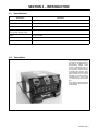
3-2. Description
This air-cooled, portable load bank
is designed to provide an adjust-
able load for troubleshooting or
demonstrating welding power
sources or generators. It has 1/2
inch (12.7 mm) diameter connec-
tion terminals for universal hookup
of welding power sources. Stan-
dard equipment includes analog
meters for both ac and dc output
with jacks for external metering
connections and a 13 foot (3.9m)
115 volts ac input power cord with
plug.
This unit has a maximum capacity
of 350 amperes, 35 volts AC or DC,
12.25 kilowatts.

OM-2807 Page 12
SECTION 4 − INSTALLATION
4-1. Selecting A Location And Moving Portable Load Bank
17-1/2 in.
(445 mm)**
loc_2 3/96 - 801 303-B / 801 319-B
! Do not move or operate unit
where it could tip.
1 Lifting Handle
Use handle to lift unit.
2 Hand Cart
Use cart or similar device to move
unit.
3 115 Volts AC Plug
4 115 Volts AC Receptacle
Locate unit near correct input
power supply. Connect input power
plug to proper 115 VAC receptacle.
Unit draws less than 1 ampere on
115 VAC.
Cord must be plugged in for unit
to operate properly.
17-5/8 in.
(448 mm)*
11-1/4 in.
(286 mm)
Movement
1
2
Location And Airflow
Dimensions And Weight
46 lb (20.9 kg)
4
* Add 3 in. (76 mm) For
Handle On Left Side
** Add 1-3/4 in. (45 mm)
For Terminal Covers
18 in.
(460 mm)
18 in.
(460 mm)
3

OM-2807 Page 13
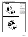
4-2. Cable Connections To Welding Equipment
802 222 / 802 223
! Turn Off welding power
source or stop engine on
welding generator before
making any connections.
1 Welding Power Source Or
Welding Generator
2 Customer-supplied 1/0 AWG
Cables−−Use Shortest Cables
As Possible
3 Portable Load Bank
4 Terminal Lugs
Install terminal lugs of proper am-
perage capacity and hole size for
connecting to output / input termi-
nals on equipment and load bank.
The load bank has 1/2 inch (12.7
mm) diameter terminal studs.
For connections to equipment with
other type output terminals, obtain
and install proper connectors.
Make cable connections to equip-
ment DC or AC output terminals as
shown; polarity is not important.
1
2
Connections To Welding Power Source
1
3
4
4
2
3
4
4
Connections To Welding Generator

OM-2807 Page 14
SECTION 5 − OPERATION
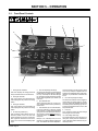
5-1. Front Panel Controls
1 Analog AC/DC Voltmeter
This meter displays the voltage present at
the input terminal studs on the load bank.
2 Analog DC Ammeter
This meter displays the approximate DC
load amperage of the power source being
tested.
3 Analog AC Ammeter
This meter displays the approximate AC
load amperage of the power source being
tested.
4 AC Jack Plug Switch (S1)
This momentary switch defaults to the AC
Ammeter position. Press and hold this
switch downward to send the current feed-
back signal from the internal current trans-
former out to the AC Load Amperage jack
plugs.
5 AC Load Amperage Jack Plugs
An external AC Ammeter can be plugged in
to these jacks. An output signal of 1 Amp AC
for every 100 Amps AC that flows through
the load bank is present at these plugs when
the AC Jack Plug Switch (see number 4) is
held down.
6 Input Terminal Stud
These connection points are 1/2 inch (12.7
mm) diameter terminal studs protected by
rubber boots.
7 Load Switches (50 A Circuit Breakers)
Use these switches to select the desired
load. There are 7 of these 50 Amp Breakers
giving this unit a total capacity of 350 Amps.
Set switches to handle MORE than the re-
quired load before turning on the welding
equipment.
Example: For a 200 Amp load, turn On a
minimum of 5 switches before applying the
load. The switches can then be adjusted un-
der load, but there must be at least 1 switch
On for every 50 Amps of applied load. The
switches are all identically rated at 50 Amps;
therefore, any combination of switches can
be On.
8 DC Load Amperage Jack Plugs
An external DC Voltmeter can be plugged in
to these jacks. An output signal of 1 mV DC
for every 10 Amps DC that flows through the
load bank is present at these plugs. The out-
put signal is generated from a 50 mV / 500
Amp internal shunt.
9 Fuse (F1)
This 1 Amp fuse protects the Load Voltage
Jack Plugs from current faults.
10 Load Voltage Jack Plugs
An external Voltmeter can be plugged in to
these jacks. These points are connected di-
rectly to the input terminal studs and are pro-
tected by Fuse F1.
1
5
6
6
6
2
3
4
7
8
9
10

OM-2807 Page 15
5-2. Rated Output Testing Procedure
! This procedure requires that the load bank and welding power source/welding generator electrical power be ON.
For this procedure, the load bank is used to determine if a welding power source or welding generator is supplying rated output. Rated output
usually indicates the welding power source or welding generator is working correctly. To check rated output, proceed as follows:
NOTICE − High frequency can damage meters. If welding power source/welding generator is equipped with high frequency, turn it off.
Make sure load bank load-switches (circuit breakers) are off.
Prepare and connect cables to the load bank, unless cables are already connected
Make sure welding power source/welding generator to be tested is turned off, and contactor switch, if applicable, is off.
Connect leads from load bank to welding power source/welding generator output studs. Polarity is not important. (see Section 4-2).
Plug load bank power cord into receptacle (see Section 4-1).
Set load bank load-switches to 100 amps more than the welding power source/welding generator is rated for (this information is usually found
on the welding power source/welding generator rating label).
NOTICE − Failure to set load bank load-switches higher than the expected measured current may shorten switch life.
Turn on welding power source/welding generator, and if applicable, switch contactor to On position.
Adjust output of welding power source/welding generator to achieve rated output. It may be necessary to readjust load bank load-switches.
To extend life of load bank switches, turn off welding power source/welding generator contactor if applicable, or turn amperage to minimum
before adjusting switches.
NOTICE − Check load bank cables for overheating. It may be necessary to use larger size cables.
When finished with rated output test, turn welding power source/welding generator contactor switch to Off position, and then turn load bank
load-switches to Off position.
NOTICE − If welding power source/welding generator does not have a contactor switch, turn output to minimum before turning load bank load-
switches to Off position.
NOTICE − Allow a cool-down period for both the load bank and welding power source/welding generator before turning power off .
SECTION 6 − MAINTENANCE & TROUBLESHOOTING
6-1. Routine Maintenance
! Disconnect input cables and power before maintaining.
= Check = Change = Clean = Repair = Replace
* To be done by Factory Authorized Service Agent
Every
3
Months
Cables And Cords
Labels Weld Terminals
Every
6
Months
:During heavy service, clean monthly.
OR

OM-2807 Page 16
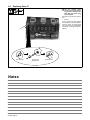
6-2. Replacing Fuse F1
! Turn Off welding power
source or stop engine on weld-
ing generator and disconnect
load bank input power plug
from receptacle.
See Parts List for size and rating of
fuse.
1 Fuse F1
Fuse F1 protects the Load Voltage
Jack Plugs from overload conditions.
If Fuse F1 opens, no voltage signal
will be present at the Load Voltage
Jack Plugs. Correct problem and re-
place F1.
1
Push And Turn
Pull Out And Push And Turn
Replace Fuse
Notes

OM-2807 Page 17
6-3. Troubleshooting Table
Trouble Remedy
Unit is completely inoperative; fan does
not run.
Be sure input power cord is plugged in and that receptacle is receiving input power.
Unit is completely inoperative; fan
runs.
Thermostat TP1 open caused by overheating. Allow cooling period for TP1 to close and remove
overload condition.
Have Factory Authorized Service Agent check relays CR1, CR2, and CR3.
Load switches trip Off when current is
applied.
Be sure at least 1 switch is On for every 50 Amps of applied load.
Have Factory Authorized Service Agent check load switches CB1-CB7.
No meter displays. Have Factory Authorized Service Agent check meters.
Load switches do not change load. Have Factory Authorized Service Agent check load switches and internal resistors.
No voltage signal at Load Voltage Jack
Plugs.
Check Fuse F1, and replace if necessary (see Section 5-2).
Notes
Page is loading ...

OM-2807 Page 19
SECTION 8 − PARTS LIST
Description
Part
No.
Dia.
Mkgs.
Item
No. Quantity
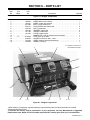
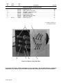
Figure 8-1. Wrapper Components
1 +183 541 WRAPPER 1... ................ .. .................................................
2 188 052 LABEL, Miller 5.375 x 6.250 1... ................. .. ...................................
3 183 451 LABEL, caution hot surfaces 1... ................. .. ..................................
4 021 385 BOOT, toggle switch lever 1... ................. .. ....................................
5 242 721 PLUG, banana jack flush mount 6... ................. .. ...............................
6 180 732 BOOT, output stud 2... ................. .. ...........................................
7 180 735 WASHER, output stud 2... ................. .. ........................................
8 181 169 SPACER, output stud 2... ................. .. ........................................
9 191 264 PLATE, breaker panel 1... ................. .. ........................................
10 NAMEPLATE, order by model and serial number 1... ............................ ................
11 F1 *012 633 FUSE, mintr gl 1A 250V 1... ....... ...... .. ......................................
12 046 432 HOLDER, fuse mintr .250 x 1.250 1... ................. .. ..............................
13 134 464 LABEL, warning general precautionary 1... ................. .. .........................
14 183 546 HANDLE, carrying 1... ................. .. ...........................................
Hardware is common and
not available unless listed.
12 3
4
5
6, 7, 891011, 1213
14
Figure 8-1. Wrapper Components
+When ordering a component originally displaying a precautionary label, the label should also be ordered.
*Recommended Spare Parts.
To maintain the factory original performance of your equipment, use only Manufacturer’s Suggested
Replacement Parts. Model and serial number required when ordering parts from your local distributor.

OM-2807 Page 20
Description
Part
No.
Dia.
Mkgs.
Item
No. Quantity
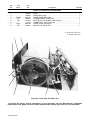
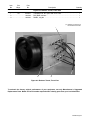
Figure 8-2. Inside View, Fan Motor End
1 183 539 BASE 1... ................. .. ......................................................
2 183 547 INSULATOR, panel 1... ................. .. ..........................................
3 SHUNT 030 081 SHUNT, meter 50MV 500A 1... .... .... .. ...................................
4 CT1 036 611 TRANSFORMER, current 500/5 1... ...... ...... .. ...............................
5 FM 241 814 MOTOR, fan 115V 50/60Hz 1400/1650 rpm 1... ...... ...... .. .....................
6 115 104 CONNECTOR, clamp cable .500 1... ................. .. ..............................
7 PLG1 082 162 CABLE, power 13ft 16ga 3c 1... ..... ..... .. ...................................
8 TE1 038 617 BLOCK, term 30A 2P frict 1... ...... ...... .. .....................................
Hardware is common and
not available unless listed.
12
4536
7
8
7
Figure 8-2. Inside View, Fan Motor End
To maintain the factory original performance of your equipment, use only Manufacturer’s Suggested
Replacement Parts. Model and serial number required when ordering parts from your local distributor.

OM-2807 Page 21
Description
Part
No.
Dia.
Mkgs.
Item
No. Quantity
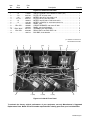
Figure 8-3. Inside Of Front Panel
1 S1 118 681 SWITCH, tgl DPDT 15A 125VAC On−None−(On) 1... ....... ...... .. ................
2 P3 025 700 FILTER, HF AC amp meter 1... ....... ...... .. ...................................
3 A2 186 814 METER, amp AC 0−350 scale 2.5 in 1... ....... ...... .. ...........................
4 P1, P2 025 701 FILTER, HF DC volt+amp meter 2... ..... ..... .. ...............................
5 A1 186 813 METER, amp DC 350−0−350 scale 2.5 in 1... ....... ...... .. .......................
6 V1 126 183 METER, volt AC/DC 0−100/0−90 scale 2.5 in 1... ....... ...... .. ....................
7 183 540 PANEL, front 1... ................. .. ................................................
8 CB1-CB7 186 860 CIRCUIT BREAKER, man reset 1P 50A 7... .... .... .. ........................
9 183 542 PANEL, mtg circuit breakers 1... ................. .. ...................................
10 Elect, Work 097 416 TERMINAL, pwr output black 2... ... ... .. ..................................
11 CR1-CR3 039 498 RELAY, ENCL 120 VAC 3PDT 10A 3... ... ... .. .............................
12 186 712 BUS BAR, circuit breaker 1... ................. .. .....................................
12 3
11 (CR3)
6
7
8
9
Hardware is common and
not available unless listed.
10
12
1011 (CR2) 11 (CR1)
4 (P1) 5 4 (P2)
Figure 8-3. Inside Of Front Panel
To maintain the factory original performance of your equipment, use only Manufacturer’s Suggested
Replacement Parts. Model and serial number required when ordering parts from your local distributor.

OM-2807 Page 22
Description
Part
No.
Dia.
Mkgs.
Item
No. Quantity
Figure 8-4. Resistor Tunnel, Rear View
1 059 726 INSULATOR, end 28... ................. .. ............................................
2 059 724 RING, retaining .937 shaft 28... ................. .. ....................................
3 049 479 BUS BAR, connecting resistor 7... ................. .. .................................
4 183 543 TUNNEL, resistors 1... ................. .. ...........................................
5 059 728 INSULATOR, support 14... ................. .. ........................................
6 059 725 RING, retaining1.437 shaft 14... ................. .. ....................................
7 183 544 SUPPORT, resistors 1... ................. .. .........................................
8 R1-R14 186 892 RESISTOR, 50A 14... .... .... .. .............................................
1, 2 3
7
Hardware is common and
not available unless listed.
45, 68
Figure 8-4. Resistor Tunnel, Rear View
To maintain the factory original performance of your equipment, use only Manufacturer’s Suggested
Replacement Parts. Model and serial number required when ordering parts from your local distributor.

OM-2807 Page 23
Description
Part
No.
Dia.
Mkgs.
Item
No. Quantity
Figure 8-5. Resistor Tunnel, Front View
1 TP1 032 810 THERMOSTAT, NC open 165F close 135F 1... ...... ...... .. ......................
2 183 548 BUS BAR, resistors 1... ................. .. ..........................................
3 183 545 PANEL, mtg fan 1... ................. .. .............................................
1
Hardware is common and
not available unless listed.
23
Figure 8-5. Resistor Tunnel, Front View
To maintain the factory original performance of your equipment, use only Manufacturer’s Suggested
Replacement Parts. Model and serial number required when ordering parts from your local distributor.
Page is loading ...
Page is loading ...
Page is loading ...

Warranty Questions?
Call
1-800-4-A-MILLER
for your local
Miller distributor.
miller_warr 2011−01
Your distributor also gives
you ...
Service
You always get the fast,
reliable response you
need. Most replacement
parts can be in your
hands in 24 hours.
Support
Need fast answers to the
tough welding questions?
Contact your distributor.
The expertise of the
distributor and Miller is
there to help you, every
step of the way.
Effective January 1, 2011
(Equipment with a serial number preface of MB or newer)
This limited warranty supersedes all previous Miller warranties and is exclusive with no other
guarantees or warranties expressed or implied.
LIMITED WARRANTY − Subject to the terms and conditions
below, Miller Electric Mfg. Co., Appleton, Wisconsin, warrants to its
original retail purchaser that new Miller equipment sold after the
effective date of this limited warranty is free of defects in material
and workmanship at the time it is shipped by Miller. THIS
WARRANTY IS EXPRESSLY IN LIEU OF ALL OTHER
WARRANTIES, EXPRESS OR IMPLIED, INCLUDING THE
WARRANTIES OF MERCHANTABILITY AND FITNESS.
Within the warranty periods listed below, Miller will repair or replace
any warranted parts or components that fail due to such defects in
material or workmanship. Miller must be notified in writing within
thirty (30) days of such defect or failure, at which time Miller will
provide instructions on the warranty claim procedures to be
followed.
Miller shall honor warranty claims on warranted equipment listed
below in the event of such a failure within the warranty time
periods. All warranty time periods start on the delivery date of the
equipment to the original end-user purchaser, and not to exceed
one year after the equipment is shipped to a North American
distributor or eighteen months after the equipment is shipped to an
International distributor.
1. 5 Years Parts — 3 Years Labor
* Original main power rectifiers only to include SCRs,
diodes, and discrete rectifier modules
2. 3 Years — Parts and Labor
* Engine Driven Welding Generators
(NOTE: Engines are warranted separately by the
engine manufacturer.)
* Inverter Power Sources (Unless Otherwise Stated)
* Plasma Arc Cutting Power Sources
* Process Controllers
* Semi-Automatic and Automatic Wire Feeders
* Smith 30 Series Flowgauge and Flowmeter
Regulators (No Labor)
* Transformer/Rectifier Power Sources
* Water Coolant Systems (Integrated)
3. 2 Years — Parts
* Auto-Darkening Helmet Lenses (No Labor)
4. 1 Year — Parts and Labor Unless Specified
* Automatic Motion Devices
* CoolBelt and CoolBand Blower Unit (No Labor)
* External Monitoring Equipment and Sensors
* Field Options
(NOTE: Field options are covered for the remaining
warranty period of the product they are installed in, or
for a minimum of one year — whichever is greater.)
* Flowgauge and Flowmeter Regulators (No Labor)
* RFCS Foot Controls (Except RFCS-RJ45)
* Fume Extractors
* HF Units
* ICE Plasma Cutting Torches (No Labor)
* Induction Heating Power Sources, Coolers, and
Electronic Controls/Recorders
* Load Banks
* Motor Driven Guns (w/exception of Spoolmate
Spoolguns)
* PAPR Blower Unit (No Labor)
* Positioners and Controllers
* Racks
* Running Gear/Trailers
* Spot Welders
* Subarc Wire Drive Assemblies
* Water Coolant Systems (Non-Integrated)
* Weldcraft-Branded TIG Torches (No Labor)
* Wireless Remote Foot/Hand Controls and Receivers
* Work Stations/Weld Tables (No Labor)
5. 6 Months — Parts
* Batteries
* Bernard Guns (No Labor)
* Tregaskiss Guns (No Labor)
6. 90 Days — Parts
* Accessory (Kits)
* Canvas Covers
* Induction Heating Coils and Blankets, Cables, and
Non-Electronic Controls
* M-Guns
* MIG Guns and Subarc (SAW) Guns
* Remote Controls and RFCS-RJ45
* Replacement Parts (No labor)
* Roughneck Guns
* Spoolmate Spoolguns
Miller’s True Blue Limited Warranty shall not apply to:
1. Consumable components; such as contact tips,
cutting nozzles, contactors, brushes, relays, work
station table tops and welding curtains, or parts that
fail due to normal wear. (Exception: brushes and
relays are covered on all engine-driven products.)
2. Items furnished by Miller, but manufactured by others,
such as engines or trade accessories. These items are
covered by the manufacturer’s warranty, if any.
3. Equipment that has been modified by any party other than
Miller, or equipment that has been improperly installed,
improperly operated or misused based upon industry
standards, or equipment which has not had reasonable
and necessary maintenance, or equipment which has
been used for operation outside of the specifications for
the equipment.
MILLER PRODUCTS ARE INTENDED FOR PURCHASE AND
USE BY COMMERCIAL/INDUSTRIAL USERS AND PERSONS
TRAINED AND EXPERIENCED IN THE USE AND
MAINTENANCE OF WELDING EQUIPMENT.
In the event of a warranty claim covered by this warranty, the
exclusive remedies shall be, at Miller’s option: (1) repair; or (2)
replacement; or, where authorized in writing by Miller in
appropriate cases, (3) the reasonable cost of repair or
replacement at an authorized Miller service station; or (4) payment
of or credit for the purchase price (less reasonable depreciation
based upon actual use) upon return of the goods at customer’s risk
and expense. Miller’s option of repair or replacement will be F.O.B.,
Factory at Appleton, Wisconsin, or F.O.B. at a Miller authorized
service facility as determined by Miller. Therefore no
compensation or reimbursement for transportation costs of any
kind will be allowed.
TO THE EXTENT PERMITTED BY LAW, THE REMEDIES
PROVIDED HEREIN ARE THE SOLE AND EXCLUSIVE
REMEDIES. IN NO EVENT SHALL MILLER BE LIABLE FOR
DIRECT, INDIRECT, SPECIAL, INCIDENTAL OR
CONSEQUENTIAL DAMAGES (INCLUDING LOSS OF
PROFIT), WHETHER BASED ON CONTRACT, TORT OR ANY
OTHER LEGAL THEORY.
ANY EXPRESS WARRANTY NOT PROVIDED HEREIN AND
ANY IMPLIED WARRANTY, GUARANTY OR
REPRESENTATION AS TO PERFORMANCE, AND ANY
REMEDY FOR BREACH OF CONTRACT TORT OR ANY
OTHER LEGAL THEORY WHICH, BUT FOR THIS PROVISION,
MIGHT ARISE BY IMPLICATION, OPERATION OF LAW,
CUSTOM OF TRADE OR COURSE OF DEALING, INCLUDING
ANY IMPLIED WARRANTY OF MERCHANTABILITY OR
FITNESS FOR PARTICULAR PURPOSE, WITH RESPECT TO
ANY AND ALL EQUIPMENT FURNISHED BY MILLER IS
EXCLUDED AND DISCLAIMED BY MILLER.
Some states in the U.S.A. do not allow limitations of how long an
implied warranty lasts, or the exclusion of incidental, indirect,
special or consequential damages, so the above limitation or
exclusion may not apply to you. This warranty provides specific
legal rights, and other rights may be available, but may vary from
state to state.
In Canada, legislation in some provinces provides for certain
additional warranties or remedies other than as stated herein, and
to the extent that they may not be waived, the limitations and
exclusions set out above may not apply. This Limited Warranty
provides specific legal rights, and other rights may be available,
but may vary from province to province.
Page is loading ...
-
 1
1
-
 2
2
-
 3
3
-
 4
4
-
 5
5
-
 6
6
-
 7
7
-
 8
8
-
 9
9
-
 10
10
-
 11
11
-
 12
12
-
 13
13
-
 14
14
-
 15
15
-
 16
16
-
 17
17
-
 18
18
-
 19
19
-
 20
20
-
 21
21
-
 22
22
-
 23
23
-
 24
24
-
 25
25
-
 26
26
-
 27
27
-
 28
28
-
 29
29
-
 30
30
-
 31
31
-
 32
32


Miller MB100177U Owner's manual
- Category
- Welding System
- Type
- Owner's manual
- This manual is also suitable for
Ask a question and I''ll find the answer in the document
Finding information in a document is now easier with AI
in other languages
Related papers
-
Miller LBP-350 Owner's manual
-
-
-
Miller MB471323U Owner's manual
-
-
-
-
-
Miller MH404001V Owner's manual
-