Page is loading ...

Com-Tech 810 and 1610 Amplifier Service Manual
]
Rev. 0
KSVCCT810/1610
8/98
Commercial Audio
E106377
®
120 VAC North
American Units:
© 1998 by Crown International, Inc., P.O. Box 1000, Elkhart, Indiana 46515-1000 U.S.A. Telephone:
219-294-8000.
Com-Tech
amplifiers are produced by the Professional Audio Division of Crown
International, Inc. Trademark Notice:
SmartAmp
™
and
Grounded Bridge
™
are trademarks and
Amcron
,
®
Crown
,
®
Com-Tech
,
®
IOC
,
®
ODEP
,
®
IQ System
,
®
P.I.P.
®
and
TEF
®
are registered trademarks of Crown
International, Inc. Other trademarks are the property of their respective owners.
Models:
Com-Tech 810 & 1610
Some models may be exported under the name Amcron.
®
COM-TECH®
®
For
Canada
Service Manual
[

Com-Tech 810 and 1610 Amplifier Service Manual
]
Rev. 0
À PRÉVENIR LE CHOC
ÉLECTRIQUE N’ENLEVEZ
PAS LES COUVERTURES.
RIEN DES PARTIES
UTILES À L’INTÉRIEUR.
DÉBRANCHER LA BORNE
AVANT D’OUVRIR LA
MODULE EN ARRIÈRE.
TO PREVENT ELECTRIC SHOCK DO
NOT REMOVE TOP OR BOTTOM
COVERS. NO USER SERVICEABLE
PARTS INSIDE. REFER SERVICING
TO QUALIFIED SERVICE
PERSONNEL. DISCONNECT
POWER CORD BEFORE REMOVING
REAR INPUT MODULE TO ACCESS
GAIN SWITCH.
CAUTION
AVIS
WARNING
TO REDUCE THE RISK OF ELECTRIC
SHOCK, DO NOT EXPOSE THIS
EQUIPMENT TO RAIN OR MOISTURE!
The information furnished in this manual does not include all of the details of design, production, or variations of
the equipment. Nor does it cover every possible situation which may arise during installation, operation or
maintenance. If you need special assistance beyond the scope of this manual, please contact the Crown Tech-
nical Support Group.
Mail:
P.O. Box 1000, Elkhart IN 46515-1000
Shipping:
Plant 2 SW, 1718 W. Mishawaka Rd., Elkhart, IN 46517
Phone:
(800) 342-6939/(219) 294-8200
FAX:
(219) 294-8301
I

Com-Tech 810 and 1610 Amplifier Service Manual
]
Rev. 0
Table of Contents
1 Introduction .............................................................................. 1-1
1.1 The Com-Tech Series ....................................................... 1-1
1.2 Warranty ........................................................................... 1-1
2 Specifications .......................................................................... 2-1
2.1 Performance ..................................................................... 2-1
2.2 Power ............................................................................... 2-1
2.3 Controls............................................................................ 2-1
2.4 Indicators ......................................................................... 2-2
2.5 Input/Output ..................................................................... 2-2
2.6 Output Signal ................................................................... 2-2
2.7 Protection ......................................................................... 2-2
2.8 Construction ..................................................................... 2-2
3 AC Power Draw and Thermal Dissipation ................................ 3-1
4 AC Mains Voltage Conversion ................................................. 4-1
4.1 Com-Tech Voltage Conversion ........................................ 4-1
4.1.1 120 VAC, 60 Hz Units .............................................. 4-1
4.1.2 100/120 VAC Export Units ....................................... 4-1
4.1.3 220/240 VAC Export Units ....................................... 4-1
5 Theory ...................................................................................... 5-1
5.1 Overview .......................................................................... 5-1
5.2 Front End Operation ......................................................... 5-1
5.2.1 Balanced Gain Stage (BGS) .................................... 5-1
5.2.2 Variable Gain Stage (VGS) ...................................... 5-1
5.2.3 Error Amp................................................................. 5-2
5.3 Voltage Amplification ....................................................... 5-2
5.3.1 Voltage Translators .................................................. 5-2
5.3.2 Last Voltage Amplifiers (LVAs) ................................. 5-2
5.4 Grounded Bridge Topology ............................................. 5-3
5.4.1 High Side (HS)......................................................... 5-3
5.4.2 Low Side (LS) .......................................................... 5-4
5.5 Output Device Emulation Protection (ODEP) ................... 5-4

Com-Tech 810 and 1610 Amplifier Service Manual
]
Rev. 0
5.6 Dual Operation................................................................. 5-6
5.7 Bridge-Mono Operation ................................................... 5-6
5.8 Parallel-Mono Operation .................................................. 5-6
6 Electrical Checkout Procedures .............................................. 6-1
6.1 General Information .......................................................... 6-1
6.2 Test Procedures ............................................................... 6-1
6.2.1 Standard Initial Conditions ...................................... 6-1
6.2.2 Turn On Delay .......................................................... 6-1
6.2.3 Output Bias Adjustment ........................................... 6-1
6.2.4 ODEP Voltage Adjustment ....................................... 6-1
6.2.5 DC Offset ................................................................. 6-1
6.2.6 Quiescent Power Draw ............................................ 6-2
6.2.7 Voltage Gain ............................................................ 6-2
6.2.8 Current Sense Calibration ....................................... 6-2
6.2.9 Common Mode Rejection ........................................ 6-2
6.2.10 Current Limit .......................................................... 6-2
6.2.11 10 kHz Square Wave Response ............................ 6-2
6.2.12 20 kHz Crosstalk.................................................... 6-3
6.2.13 Output Power ......................................................... 6-3
6.2.14 ODEP Limiting ....................................................... 6-3
6.2.15 Fan Operation (optional in Com-Tech 210) ............ 6-3
6.2.16 LF Protection .......................................................... 6-4
6.2.17 Signal to Noise ...................................................... 6-4
6.2.18 Intermodulation Distortion (IMD) ............................ 6-4
6.2.19 Displays................................................................. 6-4
6.2.20 Auto Standby Operation ........................................ 6-4
6.2.21 Post Testing ........................................................... 6-4
7 Exploded Views ....................................................................... 7-1
8 Schematics and Module Documentation ................................. 8-1

Com-Tech 810 and 1610 Amplifier Service Manual
]
1-1
Rev. 0
Crown International, Inc.
Mailing
: PO Box 1000
Elkhart, IN 46515-1000
or
Shipping
: Plant 2 S.W.
1718 W. Mishawaka Rd.
Elkhart, IN 46517
Toll Free: (800) 342-6939
Phone: (219) 294-8200
FAX: (219) 294-8301
Web: www.crownaudio.com
This manual contains service information for the Crown
Com-Tech–10 Series
power amplifiers. It is designed
to be used in conjunction with the
Com-Tech
Refer-
ence Manual. Some important information is, however,
duplicated in this Service Manual in case the Refer-
ence Manual is not readily available.
NOTE: THE INFORMATION IN THIS MANUAL IS IN-
TENDED FOR USE BY AN EXPERIENCED TECHNI-
CIAN ONLY!
1.1 The Com-Tech Series
The
Com-Tech
series is a complete family of amplifiers
with a wide range of power output capabilities.
Com-
Tech
amplifiers can directly drive "constant voltage"
lines, so you can avoid the expense, distortion and
insertion loss associated with step-up transformers for
distributed loudspeaker systems.
Com-Tech
amplifi-
ers also utilize Crown's patented
ODEP
®
protection cir-
cuitry, which keeps the amplifier working under severe
conditions that would shut down a lesser amplifier. All
Com-Tech
amplifiers feature Crown's exclusive
P.I.P.
®
(Programmable Input Processor) expansion system.
The
P.I.P.
expansion system makes it easy to tailor
your amplifier to a specific application or to add future
technology as it develops.
1.2 Warranty
Each Reference Manual contains basic policies as re-
lated to the customer. For further assistance please
contact the Crown Technical Support Group at:
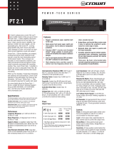
1 Introduction
Figure 1.1
Com-Tech 810
and
1610
front panels
ODEP
IOC
SPI
CH1
CH2
LOCAL
OFF
REMOTE
ODEP
IOC
SPI
CH1
CH2
LOCAL
OFF
REMOTE

Com-Tech 810 and 1610 Amplifier Service Manual
]
1-2
Rev. 0
This page intentionally left blank.

Com-Tech 810 and 1610 Amplifier Service Manual
]
2-1
Rev. 0
The following specifications apply to all models in Dual mode
with 8-ohm loads and an input sensitivity of 26 dB unless
otherwise specified.
MAP at 1 kHz: This term refers to maximum average power in
watts at 1 kHz with 0.1% THD.
Full Bandwidth Power: This term refers to maximum average
power in watts from 20 Hz to 20 kHz with 0.1% THD.
120 VAC, 60 Hz Units: These North American units have dedi-
cated transformers for 120 VAC, 60 Hz power mains.
100/120 VAC Units: These units have two-tap transformers
that accept a 50- or 60-Hz AC line, and can be configured
for 100 or 120 VAC mains.
220/240 VAC Units: These units have two-tap transformers
that accept a 50- or 60-Hz AC line, and can be configured
for 220 or 240 VAC mains.
2.1 Performance
Frequency Response: ±0.1 dB from 20 Hz to 20 kHz at 1
Watt (See Figure 2.1).
Phase Response: ±10 degrees from 10 Hz to 20 kHz at 1
Watt (See Figure 2.4).
Hum and Noise: A-weighted, 105 dB below full bandwidth
power; No weighting, 100 dB below full bandwidth power.
Total Harmonic Distortion (THD): Less than 0.05% at full power
from 20 Hz to 1 kHz increasing linearly to 0.1% at 20 kHz.
Intermodulation Distortion (IMD): (60 Hz and 7 kHz 4:1) Less
than 0.05% from -35 dB to full power bandwidth.
Damping Factor: Greater than 1000 from 10 Hz to 400 Hz
(See Figure 2.2).
Crosstalk: Greater than 70 dB down at 10 kHz. (See Figure
2.5).
Common Mode Rejection Ration (CMRR): Better than 70 dB.
Slew Rate: Greater than 17 volts per microsecond.
Voltage Gain: (At the maximum level setting) 20:1 ±3% or 26
dB ±0.25 dB. 90:1 ±12% or 39 dB ±1 dB with the input
sensitivity set to 0.775 volts for 70 volt output. The following
voltage gain specifications are for units with the input sensi-
tivity set to 0.775 volts for 8/4 ohm output:
Com-Tech 810:
64:1 ±12% or 36 dB ±1 dB.
Com-Tech 1610
: 85:1 ±12% or 39 dB ±1 dB.
2.2 Power
Output Power: See the minimum Guaranteed Power table in
Figures 2.6-7 for the output power specifications under a
variety of conditions.
It is extremely important to supply the amplifier with ad-
equate AC power. Power amplifiers cannot add power–they
need the required voltage and current to deliver the
undistorted rated wattages you expect.
Load Impedance: Safe with all types of loads. With 8/4 ohm
output, all
Com-Techs
are rated for 4 to 8 ohms in Dual
mode, 8 to 16 ohms in Bridge-Mono mode, and 2 to 4 ohms
in Parallel-Mono mode. With a 70 volt output, rated loads
vary among the different models for each dual/mono mode
(see the power matrices that follow).
AC Power Requirements: All units require less than 90 watts
at idle. See Section 3 for detailed information on AC power
requirements and thermal dissipation.
Low-Voltage Power Supply: ±15 VDC regulated supplies are
provided by a winding on the power transformer.
Power Cord: An appropriate AC line cord is provided with a
nominal cable length of 3 feet.
2.3 Controls
Enable: A front panel rocker switch used to turn the amplifier
on and off, and to enable the remote feature.
Input Attenuation: A detented 21-position back panel Input
Attenuation control for each channel.
Output Mode: A back panel switch for each channel used to
select 8/4-ohm or 70-volt output.
Dual/Mono: A 3-position back panel switch used to select
Dual, Bridge-Mono or Parallel-Mono operation.
Reset: A back panel push button used to reset the amplifier's
AC mains breaker.
Input Sensitivity: A three-position switch inside the
P.I.P.
com-
partment used to select an input sensitivity for both chan-
nels: 0.775 volts for MAP at 1 kHz in 8/4 ohm mode, 0.775
volts for MAP at 1 kHz in 70-volt mode, or a voltage gain of
26 dB.
2 Specifications

Com-Tech 810 and 1610 Amplifier Service Manual
]
2-2
Rev. 0
2.4 Indicators
Enable: This amber indicator shows the on/off status of the
unit's low-voltage power supply and the activation of the
energy-saving mode.
SPI
(Signal Presence Indicator): Each channel has a green
indicator that flashes to show audio output.
IOC
(Input/Output Comparator): Each channel has a yellow
indicator that flashes if the output waveform differs from the
input waveform by 0.05% or more. The LEDs act as sensi-
tive distortion indicators to provide proof of distortion-free
performance.
ODEP
(Output Device Emulation Protection):
Each channel has
a green multifunction indicator that shows the channel's re-
serve energy status. Normally, the LEDs are brightly lit to
show that reserve energy is available. In the rare event that
a channel has no reserve, its indicator will dim in proportion
to
ODEP
limiting.
2.5 Input/Output
Input Connector: A barrier block on the standard PIP2-BB
with three-terminal balanced connections for input to each
channel and test points for a DVM.
Input Impedance: Nominally 20 K ohms, balanced. Nomi-
nally 10 K ohms, unbalanced.
Input Sensitivity: Settings include 0.775 volts for 8/4-ohm
output, 0.775 volts for 70-volt output, and a voltage gain of
26 dB.
Output Connector: A back panel barrier block with two-termi-
nal connections for each output channel.
Output Impedance: Less than 10 milliohms in series with less
than 2 microhenries (see Figure 2.3).
DC Output Offset: Less than ±10 millivolts.
RSVP: An RJ11 modular connector on the back panel inter-
faces with an RSVP to provide remote control of amplifier
power on/off functions.
2.6 Output Signal
Dual: Unbalanced, two-channel.
Bridge-Mono: Balanced, single-channel. Channel 1 controls
are active; Channel 2 should be turned down. Channel 1 red
terminal is positive, referenced to ground, when the input is
positive.
Parallel-Mono: Unbalanced, single-channel. Channel 1 con-
trols are active; Channel 2 is bypassed.
2.7 Protection
Com-Tech
amplifiers are protected against shorted,open or
mismatched loads; overloaded power supplies; excessive
temperature, chain destruction phenomena, input overload
damage and high-frequency blowups. It also protects
loudspeakers from input/output DC and turn-on/turn-off
transients.
If unreasonable operating conditions occur, the patented
ODEP
circuitry proportionally limits the drive level to protect
the output devices, particularly in the case of elevated
temperature. Transformer overheating results in a temporary
shutdown of both channels. The transformer automatically
resets itself when it has cooled to a safe temperature.
Controlled by slew rate, voltage amplifiers protect against RF
burnouts, and input overload protection is provided by
current-limiting resistance at the input.
Turn On: The four-second turn on delay prevents dangerous
turn-on transients. “Soft-start” circuitry provides low inrush so
power sequencers are rarely needed with multiple units.
Note: The turn-on delay time may be changed. Contact
Crown's Technical Support Group for details.
Circuit Breaker: Circuit breaker current ratings vary based on
the
Com-Tech
model and AC mains voltage.
All 100/120 VAC Units:
Com-Tech 810
: 20 amperes.
Com-Tech 1610
: 30 amperes.
All 220/240 VAC Units:
Com-Tech 810
: 10 amperes.
Com-Tech 1610
: 20 amperes.
2.8 Construction
Durable black powdercoat finish on the steel chassis, front
panel Lexan overlay, and specially-designed flow-through
ventilation from front to side panels.
Cooling: Internal heat exchangers with on-demand forced
air cooling (fan is optional for the North American
Com-
Tech 210
).
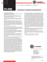
Dimensions: 19 inch (48.3 cm) standard rack mount width
(EIA RS-310-B), 16 inch (40.6 cm) depth behind mounting
surface, and 0.25 inches (0.6 cm) in front of mounting surface.
Amplifier height varies among the available models and with
different AC power requirements (see Figure 2.10).
Height A: 3.5 inches (8.9 cm)
Models:
Com-Tech
210 (All)
Com-Tech
410 (North American)

Com-Tech 810 and 1610 Amplifier Service Manual
]
2-3
Rev. 0
Height B: 5.25 inches (13.3 cm)
Models:
Com-Tech
410 (100/120 VAC, 50/60 Hz)
Com-Tech
410 (220/240 VAC, 50/60 Hz)
Com-Tech
810 (All)
Height C: 7 inches (17.8 cm)
Model:
Com-Tech
1610 (All)
Approximate Weight: Center of gravity is 6 inches (15.2
cm) behind the front mounting surface.
120 VAC, 60 Hz North American Units:
Com-Tech 810
: 47 pounds, 4 ounces
(21.5 kg) net; 50 pounds, 8 ounces
(22.9 kg) shipping weight.
Com-Tech 1610
: 57 pounds, 14 ounces
(26.3 kg) net; 66 pounds, 10 ounces
(30.2 kg) shipping weight.
100/120 VAC, 50/60 Hz Units:
Com-Tech 810
: 45 pounds, 1 ounce
(20.5 kg) net; 49 pounds, 10 ounces
(22.5 kg) shipping weight.
Com-Tech 1610
: 54 pounds, 11 ounces
(24.8 kg) net; 64 pounds, 3 ounces
(29.1 kg) shipping weight.
220-240 VAC, 50/60 Hz Units:
Com-Tech 810
: 45 pounds, 4 ounces
(20.5 kg) net; 49 pounds, 13 ounces
(22.6 kg) shipping weight.
Com-Tech 1610
: 55 pounds, 2 ounces
(25.0 kg) net; 64 pounds, 10 ounces
(29.3 kg) shipping weight.
C: 7 in
(17.8 cm)
O
F
F
O
D
E
P
I
O
C
S
P
I
C
H
1
C
H
2
B: 5.25 in
(13.3 cm)
A: 3.5 in
(8.9 cm)
19 in
(48.3 cm)
1
6
i
n
(
4
0
.
6
c
m
)
L
O
C
A
L
R
E
M
O
T
E
Figure 2.10 Mounting Dimensions

Com-Tech 810 and 1610 Amplifier Service Manual
]
2-4
Rev. 0
10 100 1 K 10 K 100 K
FREQUENCY (Hz)
+2
+1
0
–1
–2
–3
–4
dB
–5
–6
–7
4 ohm
8 ohm
1 watt
504.0
126.8
31.8
MILLIOHMS
8.0
2.0
6 dB
20
100 1 K 10 K
20 K
400
200
100
0
600
800
1000
1200
1400
FREQUENCY (Hz)
8 ohm
10 100 1 K 10 K 100 K
FREQUENCY (Hz)
Figure 2.1 Typical Frequency Response
Figure 2.2 Typical Damping Factor
Figure 2.3 Typical Output Impedance

Com-Tech 810 and 1610 Amplifier Service Manual
]
2-5
Rev. 0
Figure 2.4 Typical Phase Response
Figure 2.5 Typical Crosstalk
TEF
®
Measurement
100 1 K 10 K 20 K
FREQUENCY
(
Hz
)
dB
TECHRON TEF
®
TECHRON TEF
®
+45˚
0˚
–45˚
100 1 K 10 K 20 K
FREQUENCY
(
Hz
)
TEF
®
Measurement

Com-Tech 810 and 1610 Amplifier Service Manual
]
2-6
Rev. 0
Crown specifications are guaranteed for three years.
In an effort to provide you with as much information as possible about the high power-producing capabilities of your amplifier, we have
created the following power matrices.
Minimum Guaranteed Power Specifications
Crown’s minimum power specifications represent the absolute smallest amount of output power you can expect from your amplifier when
it is driven to full output under the given conditions. Some spaces in each matrix may be left blank because the same guarantee is not
provided for those conditions—however, your amplifier will perform well under
all conditions listed in each matrix.
When measuring power, 0.1% THD appears to be the industry standard for distortion. Two of the maximum average power specifications
shown in each minimum power matrix are measured at 0.1% THD so you can easily compare Crown specifications to those of other
manufacturers. But this high level of distortion actually allows for some clipping which is undesirable. Because of this, a maximum average
power specification at 0.05% THD is included in each minimum power matrix which represents non-clipped conditions. Although most
manufacturers do not give you power specifications at 0.05% THD, we encourage them to provide these specifications so you will have a
more realistic representation of the way amplifiers should be used in the real world—without a clipped output signal.
Many manufacturers publish power specs with a tolerance of ±1 dB or worse. This means their amplifier can deviate more than 20% in
output! A 100 watt amplifier would meet their specification if it only produced 79.4 watts. Other manufacturers qualify their specs by saying
Figure 2.6 Com-Tech 810 Minimum Power Matrix
they are “typical,” “subject to manufacturing toler-
ances,” “single channel driven” or that they are
specified with “fuses bypassed.” Each of these
statements effectively removes any performance
guarantee. In fact, some manufacturers use these
tactics to generate large power numbers, and
they don’t even print a disclaimer. We take a dif-
ferent approach at Crown—our amplifiers are
guaranteed
to meet or exceed their specifications
for three years. Further, because our published
specs are set below our “in-house” measure-
ments, you can expect
every
Crown amplifier to
meet
or
exceed
its published minimum power
specs. We believe you should get what you pay
for.
Minimum Power Notes:
All minimum power specifications are based on
0.5% regulated AC mains with THD of less than
1.0% and an ambient room temperature of 70° F
(21° C). Standard EIA power (RS-490) is not shown
here because it is identical to FTC Continuous Av-
erage Power.
1. A 1 kHz sine wave is presented to the amplifier
and the output monitored for nonlinear distor-
tion. The level is increased until THD reaches
0.1%. At this point, average power per chan-
nel is reported.
2. A sine wave is presented to the amplifier over
the range from 20 Hz to 20 kHz and the output
monitored for nonlinear distortion. The level at
each frequency is increased until THD reaches
0.1%. At this point, average power per chan-
nel is reported.
3. A 1 kHz sine wave is presented to the amplifier
and the output monitored for nonlinear distor-
tion. The level is increased until THD reaches
0.05%. At this point, average power per chan-
nel is reported.
4. Continuous power in the context of Federal
Trade Commission testing is understood to be
a minimum of five minutes of operation. Har-
monic distortion is measured as the RMS sum
total and given as a percentage of the funda-
mental output voltage. This applies for all watt-
ages greater than 0.25 watts.
Com-Tech 810 – Minimum Guaranteed Power (Watts)
Dual/Mono
Mode
Dual
(both channels
driven)
Bridge-Mono
(balanced output)
Parallel-Mono
FTC Continuous Average
At 0.1% THD
(See note 4)
1 kHz 20Hz-20kHz
Maximum Average
Load in Ohms
(Constant Voltage)
AC Mains120 VAC, 60 Hz
1 kHz
At 0.1% THD
(See note 1)
At 0.1% THD
(See note 2)
20Hz-20kHz
Dual
(both channels
driven)
Bridge-Mono
(balanced output)
Parallel-Mono
At 0.05% THD
(See note 3)
1 kHz
100/120 VAC, 50/60 Hz
Dual
(both channels
driven)
Bridge-Mono
(balanced output)
Parallel-Mono
220/240 VAC, 50/60 Hz
12.5 (70V)
4
2
25 (140V)
8
6.25 (70V)
8
4
16
12.5 (70V)
4
2
25 (140V)
8
6.25 (70V)
8
4
16
12.5 (70V)
4
2
25 (140V)
8
6.25 (70V)
8
4
16
490
305
460
975
610
920
965
610
915
460
300
425
925
600
855
925
600
855
485
310
440
965
620
885
940
615
875
460
295
455
935
600
905
440
290
415
885
580
825
470
305
430
920
605
855
480
300
455
965
605
905
950
600
905
460
295
420
915
595
850
920
595
845
485
310
435
955
615
875
930
610
870
470
300
450
950
605
905
950
605
910
445
295
410
890
595
830
895
595
830
465
310
425
930
615
865
920
600
855
455
290
445
905
600
880
425
290
400
840
575
800
450
300
420
875
600
840

Com-Tech 810 and 1610 Amplifier Service Manual
]
2-7
Rev. 0
Figure 2.7 Com-Tech 1610 Minimum Power Matrix
Com-Tech 1610 – Minimum Guaranteed Power (Watts)
Dual/Mono
Mode
Dual
(both channels
driven)
Bridge-Mono
(balanced output)
Parallel-Mono
FTC Continuous Average
At 0.1% THD
(See note 4)
1 kHz 20Hz-20kHz
Maximum Average
Load in Ohms
(Constant Voltage)
AC Mains120 VAC, 60 Hz
1 kHz
At 0.1% THD
(See note 1)
At 0.1% THD
(See note 2)
20Hz-20kHz
Dual
(both channels
driven)
Bridge-Mono
(balanced output)
Parallel-Mono
At 0.05% THD
(See note 3)
1 kHz
100/120 VAC, 50/60 Hz
Dual
(both channels
driven)
Bridge-Mono
(balanced output)
Parallel-Mono
220/240 VAC, 50/60 Hz
6.25 (70V)
4
2
12.5 (140V)
8
3.13 (70V)
8
4
16
6.25 (70V)
4
2
12.5 (140V)
8
3.13 (70V)
8
4
16
6.25 (70V)
4
2
12.5 (140V)
8
3.13 (70V)
8
4
16
870
540
960
1745
1080
1805
1745
1080
1780
815
535
860
1625
1070
1700
1660
1080
1700
840
545
875
1675
1090
1755
1650
1075
1745
810
520
910
1595
1040
1725
775
515
830
1545
1035
1640
785
525
755
1550
910
1315
860
535
955
1725
1070
1795
1720
1070
1760
805
530
850
1615
1060
1695
1640
1070
1690
840
540
870
1665
1075
1745
1635
1065
1735
850
540
960
1700
1075
1770
1690
1075
1745
530
815
1055
1625
1060
1620
540
850
1070
1710
1065
1715
510
1040
510
1020
505
900

Com-Tech 810 and 1610 Amplifier Service Manual
]
2-8
Rev. 0
Maximum Power Specifications
Crown’s maximum power specifications represent the largest amount of output power you can expect from your amplifier
when it is driven to full output under the given conditions. These specifications can be used to prevent loudspeaker and
hearing damage.
The maximum power matrices include specifications for single cycle and 40-millisecond burst sine waves. Burst signals act
like large transient peaks that are present in common source signals. Loudspeakers can respond to a single cycle burst, so
the single cycle burst specifications should be used to help you protect your loudspeakers. In contrast, a 40 millisecond burst
represents the typical response time of the human ear. Your ear will not respond to the entire dynamic change of a burst that
lasts less than 40 milliseconds.
The burst power specifications are provided at 0.05% THD which is a practical low distortion condition. Operating the amplifier
at levels higher than 0.05% THD can result in output power levels that are higher than those listed in the maximum power
matrices.
Figure 2.8 Com-Tech 810 Maximum Power Matrix
Maximum Power Notes:
All maximum power specifica-
tions are based on 0.5% regu-
lated AC mains with THD of less
than 1.0% and an ambient
room temperature of 70° F (21°
C). Although it is an unusual
condition, your amplifier can
function well with AC mains volt-
ages up to 10% over the speci-
fied line voltage. With overvolt-
age conditions, your amplifier
may be capable of delivering
instantaneous power levels up
to 20% greater than the speci-
fications in the matrix.
1. A single cycle sine wave is
presented to the amplifier
and monitored for nonlinear
distortion. The average
power during the burst is
reported. Loudspeakers
must be able to withstand
this level if they are to be
safely used with this ampli-
fier.
2. A 40 millisecond sine wave
burst (10 percent duty
cycle) is presented to the
amplifier and monitored for
nonlinear distortion. Aver-
age power during the burst
is reported. This power
level is a measurement of
the amplifier’s maximum
transient power that can be
perceived by the human
ear.
12.5 (70V)
4
Dual
(both channels
driven)
Bridge-Mono
(balanced output)
Parallel-Mono
2
25 (140V)
8
6.25 (70V)
8
4
16
Dual
(both channels
driven)
Bridge-Mono
(balanced output)
Parallel-Mono
Com-Tech 810 –
Maximum Power (Watts)
Dual/Mono
Mode
40 Millisecond Tone Burst
At 0.05% THD
(See note 2)
Single Cycle Tone Burst
At less than 0.05% THD
(See note 1)
50 Hz 1 kHz
Load in Ohms
(Constant Voltage)
20 Hz 50 Hz 1 kHz 7 kHz 7 kHz
AC Mains120 VAC, 60 Hz 100/120 VAC, 50/60 Hz
Dual
(both channels
driven)
Bridge-Mono
(balanced output)
Parallel-Mono
220/240 VAC, 50/60 Hz
12.5 (70V)
4
2
25 (140V)
8
6.25 (70V)
8
4
16
12.5 (70V)
4
2
25 (140V)
8
6.25 (70V)
8
4
16
515
320
480
1010
640
980
1060
645
975
460
230
475
915
600
920
900
600
915
475
305
475
930
605
920
910
600
915
575
340
530
1120
680
1045
1160
685
1045
605
295
545
1195
705
1085
1195
700
1070
610
360
545
1190
705
1085
1185
710
1080
695
385
590
1405
770
1185
1390
765
1170
750
375
610
1500
810
1230
1485
805
1210
755
405
615
1530
815
1225
1475
790
1225
690
375
575
1385
755
1145
1380
755
1135
730
370
595
1480
790
1190
1450
780
1185
740
395
590
1470
785
1180
1415
770
1175
545
320
480
1060
650
960
1100
650
985
555
275
510
1110
665
990
1075
660
975
570
340
505
1095
675
980
1085
665
985
470
300
455
945
595
910
950
590
910
470
235
470
935
600
910
920
600
905
485
305
475
945
605
910
920
595
910
495
310
475
995
620
955
985
615
945
490
245
490
980
630
955
960
625
945
500
320
490
985
635
945
955
620
940

Com-Tech 810 and 1610 Amplifier Service Manual
]
2-9
Rev. 0
Figure 2.9 Com-Tech 1610 Maximum Power Matrix
6.25 (70V)
4
Dual
(both channels
driven)
Bridge-Mono
(balanced output)
Parallel-Mono
2
12.5 (140V)
8
3.13 (70V)
8
4
16
Dual
(both channels
driven)
Bridge-Mono
(balanced output)
Parallel-Mono
Com-Tech 1610 – Maximum Power (Watts)
Dual/Mono
Mode
40 Millisecond Tone Burst
At 0.05% THD
(See note 2)
Single Cycle Tone Burst
At less than 0.05% THD
(See note 1)
50 Hz 1 kHz
Load in Ohms
(Constant Voltage)
20 Hz 50 Hz 1 kHz 7 kHz 7 kHz
AC Mains120 VAC, 60 Hz 100/120 VAC, 50/60 Hz
Dual
(both channels
driven)
Bridge-Mono
(balanced output)
Parallel-Mono
220/240 VAC, 50/60 Hz
6.25 (70V)
4
2
12.5 (140V)
8
3.13 (70V)
8
4
16
6.25 (70V)
4
2
12.5 (140V)
8
3.13 (70V)
8
4
16
780
525
950
1600
1050
1770
1590
1140
1895
820
555
955
1635
1090
1895
1640
1090
1845
800
535
885
1600
1055
1800
1615
1065
1855
1000
600
1035
1995
1185
1980
1985
1170
2015
1060
655
1100
2095
1285
2165
2105
1300
2110
1060
630
1025
2060
1225
2115
2100
1230
2080
1245
670
1205
2480
1330
2315
2465
1330
2375
1370
750
1295
2700
1475
2550
2715
1470
2530
1295
700
1210
2580
1410
2475
2585
1415
2450
1215
655
1170
2420
1285
2225
2390
1300
2280
1335
720
1255
2680
1440
2490
2630
1425
2430
1245
685
1165
2520
1365
2395
2525
1380
2315
915
555
925
1875
1145
1785
1830
1130
1880
1005
610
1025
1930
1200
1985
1955
1195
1965
955
590
960
1915
1155
1935
1920
1175
1940
840
525
875
1670
1050
1675
1665
1045
1715
835
550
895
1650
1080
1760
1655
1080
1745
820
530
845
1630
1050
1720
1635
1055
1720
870
545
905
1745
1090
1735
1715
1080
1780
870
570
930
1735
1130
1825
1725
1120
1810
850
550
875
1695
1095
1800
1700
1095
1785

Com-Tech 810 and 1610 Amplifier Service Manual
]
2-10
Rev. 0
This page intentionally left blank.

Com-Tech 810 and 1610 Amplifier Service Manual
]
3-1
Rev. 0
3 AC Power Draw and
Thermal Dissipation
“Soft-Star“Soft-Star
“Soft-Star“Soft-Star
“Soft-Star
t”t”
t”t”
t” inrush current limiting protects the house
circuit breaker when several amps are turned on simul-
taneously.
This section provides detailed information about the
amount of power and current drawn from the AC mains
by the
Com-Tech
amplifiers and the amount of heat pro-
duced under various conditions. The calculations pre-
sented here are intended to provide a realistic and
reliable depiction of the amplifier. The following assump-
tions or approximations were made:
• The amplifier’s available channels are loaded, and full
power is being delivered.
• Amplifier efficiency at standard 1 kHz power is estimated
to be 65%.
• In 8/4 ohm mode, typical quiescent power draw is 55
watts for the
Com-Tech 810
and 70 watts for the
Com-
Tech 1610
.
• In 70 volt mode, typical quiescent power draw is
90 watts for the
Com-Tech 810
and
1610
.
• When running at full speed, typical power draw for the
internal fan is 11 watts for the
Com-Tech 810
and 17
watts for the
Com-Tech
1610
.
• Quiescent thermal dissipation is related .
• The estimated duty cycles take into account the typical
crest factor for each type of source material.
• Duty cycle of pink noise is 50%.
• Duty cycle of highly compressed rock ‘n’ roll midrange
is 40%.
• Duty cycle of rock ‘n’ roll is 30%.
• Duty cycle of background music is 20%.
• Duty cycle of continuous speech is 10%.
• Duty cycle of infrequent paging is 1%.
Here are the equations used to calculate the data pre-
sented in Figures 3.1 and 3.2:
AC Mains Power
Draw (watts)
=
Total output power with all
channels driven (watts)
x
Duty
Cycle
Amplifier Efficiency (.65)
+
Quiescent Power
Draw (watts)
The value used for quiescent power draw includes both
the amplifier’s quiescent power draw for the selected
output mode and the power drawn by the fan if one is
installed (these values are listed in the previous column).
The following equation converts power draw in watts to
current draw in amperes:
Current Draw
(amperes)
=
AC
M
a
i
ns
P
ower
Draw (watts)
x
AC Mains
Volta
g
e
Power
Factor
(
.83
)
The power factor of 0.83 is needed to compensate for
the difference in phase between the AC mains voltage
and current. The following equation is used to calculate
thermal dissipation:
Total output power with all
channels driven (watts)
Thermal
Dissipation
(btu/hr)
=
+
Quiescent Power
Draw (watts)
x
.35
Duty
Cycle
x
Amplifier Efficiency (.65)
()
x
3.415
The constant 0.35 is inefficiency (1.00–0.65) and the fac-
tor 3.415 converts watts to btu/hr. Thermal dissipation in
btu is divided by the constant 3.968 to get kcal. If you
plan to measure output power under real-world condi-
tions, the following equation may also be helpful:
Total measured output power
from all channels (watts)
Thermal
Dissipation
(btu/hr)
=
+
Quiescent Power
Draw (watts)
.35
x
Amplifier Efficiency (.65)
()
x
3.415
Figure 3.1 Com-Tech 810 Power Draw, Current Draw and Thermal Dissipation at Various Duty Cycles
3-1
Figure 3.2 Com-Tech 1610 Power Draw, Current Draw and Thermal Dissipation at Various Duty Cycles
8 Ohm Dual / 16 Ohm Bridge-Mono / 4 Ohm Parallel-Mono
L O A D
50%
40%
30%
20%
10%
535
440
350
255
160
785
670
560
450
335
820
670
520
370
220
285
240
195
150
100
810
670
525
385
245
1190
1020
850
680
510
6.4
5.3
4.2
3.0
1.9
9.9
8.0
6.2
4.4
2.6
9.7
8.0
6.3
4.6
2.9
Duty
Cycle
AC Mains
Power
Draw
(Watts)
btu/hr
Current Draw (Amps)
2.9
2.4
1.9
1.4
0.9
4.5
3.7
2.8
2.0
1.2
4.4
3.6
2.9
2.1
1.3
4 Ohm Dual / 8 Ohm Bridge-Mono / 2 Ohm Parallel-Mono 70 V
Com-Tech 810
200
170
140
115
85
kcal/hr
1125
945
765
585
405
300
260
215
170
130
100-120 V 220-240 V
Thermal Dissipation
btu/hr
Current Draw (Amps)
kcal/hr100-120 V 220-240 V
Thermal Dissipation
btu/hr
Current Draw (Amps)
kcal/hr100-120 V 220-240 V
Thermal Dissipation
AC Mains
Power
Draw
(Watts)
AC Mains
Power
Draw
(Watts)
8 Ohm Dual / 16 Ohm Bridge-Mono / 4 Ohm Parallel-Mono
L O A D
50%
40%
30%
20%
10%
920
755
590
425
260
1300
1100
905
705
510
1435
1165
895
630
360
485
400
320
240
160
1590
1295
1000
700
405
2140
1790
1435
1085
730
11.1
9.1
7.1
5.1
3.1
17.3
14.0
10.8
7.6
4.3
19.1
15.6
12.0
8.4
4.9
Duty
Cycle
AC Mains
Power
Draw
(Watts)
btu/hr
Current Draw (Amps)
5.0
4.1
3.2
2.3
1.4
7.8
6.4
4.9
3.4
2.0
8.7
7.1
5.5
3.8
2.2
4 Ohm Dual / 8 Ohm Bridge-Mono / 2 Ohm Parallel-Mono 70 V
Com-Tech 1610
330
280
230
180
130
kcal/hr
1915
1590
1270
950
630
540
450
365
275
185
100-120 V 220-240 V
Thermal Dissipation
btu/hr
Current Draw (Amps)
kcal/hr100-120 V 220-240 V
Thermal Dissipation
btu/hr
Current Draw (Amps)
kcal/hr100-120 V 220-240 V
Thermal Dissipation
AC Mains
Power
Draw
(Watts)
AC Mains
Power
Draw
(Watts)

Com-Tech 810 and 1610 Amplifier Service Manual
]
4-1
Rev. 0
4 AC Mains Voltage
Conversion
Figure 4.1 Control PCA Layout
4.1
Com-Tech
Voltage Conversion
Due to Crown's distribution of
Com-Tech
amplifiers all
over the world, not all of these amplifiers are built with
the same power supply components. Refer to the fol-
lowing text to see if your unit is compatible with the
voltage you need. See figure 4.1 for Control PCA lay-
out.
4.1.1 120 VAC, 60 Hz Units
These North American units have dedicated transform-
ers for 120 VAC, 60 Hz power mains. These units are
not convertable for use at any other voltage or fre-
quency.
4.1.2 100/120 VAC Export Units
These units have two-tap transformers that accept a
50 or 60 Hz AC line, and can be configured for 100 or
120 VAC. To convert from one voltage to another, switch
the BLK/RED and BLK/WHT wires. Refer to the follow-
ing chart.
Control Board Wiring
Line Wiring Connections
Voltage BLK/RED BLK/WHT
100V W9 W2
120V W2 W9
4.1.3 220/240 VAC Export Units
These units have two-tap transformers that accept a
50 or 60 Hz line, and can be configured for 220 or 240
VAC. To convert from one voltage to another, switch
the BLK/YEL and BLK/WHT wires. Refer to the follow-
ing chart.
Control Board Wiring
Line Wiring Connections
Voltage BLK/YEL BLK/WHT
220V W9 W2
240V W2 W9
J901
R958
R959
R960
R940
R939
R941
R942
TRANSFORMER
THERMAL
SWITCH
J902
Q931
R961
K930
C935
C938
C931
C932
C930
U930
U931
U932
L930
Z902
Z903
W1
W2
W7
W9
W8
W3
W4
W10
W6
W5
PWA

Com-Tech 810 and 1610 Amplifier Service Manual
]
4-2
Rev. 0
This page intentionally left blank.

Com-Tech 810 and 1610 Amplifier Service Manual
]
5-1
Rev. 0
5.1 Overview
Com-Tech
amplifiers incorporate several new technologi-
cal advancements, including real-time computer simula-
tion, low-stress output stages, an advanced heat sink
embodiment and the Programmable Input Processor
(
P.I.P.
) expansion system.
Custom circuitry is incorporated to limit temperature and
current to safe levels, making it highly reliable and toler-
ant of faults. Unlike many lesser amplifiers, it can oper-
ate at its voltage and current limits without
self-destructing.
Real-time computer simulation is used to create an ana-
log of the junction temperature of the output transistors
(hereafter referred to as the output devices). Current is
limited only when the device temperature becomes ex-
cessive (and by the minimum amount required). This
patented approach, called Output Device Emulation Pro-
tection (or
ODEP
) maximizes the available output power
and protects against overheating—the major cause of
device failure.
The amplifier is protected from all common hazards that
plague high-power amplifiers, including shorted, open
or mismatched loads; overloaded power supplies; ex-
cessive temperature and chain-destruction phenomenon;
input overload; high-frequency blowups, internal faults;
and input and output DC.
The four-quadrant topology used in a
Com-Tech
amplifier’s output stages is called the
grounded bridge
.
This patented topology makes full use of the power sup-
ply, providing peak-to-peak voltages to the load that are
twice the voltage seen by the output devices.
As its name suggests, the
grounded bridge
topology is
referenced to ground. Composite devices are con-
structed to function as large NPN and PNP devices to
handle currents which exceed the limits of available de-
vices. Each output stage has two composite NPN de-
vices and two composite PNP devices.
The devices connected to the load are referred to as
“high-side NPN and PNP” and the devices connected to
ground are referred to as “low-side NPN and PNP.” Posi-
tive current is delivered to the load by increasing con-
ductance simultaneously in the high-side NPN and
low-side PNP stage, while synchronously decreasing
conductance of the high-side PNP and low-side NPN.
The two channels may be used together to double the
voltage (Bridge-Mono) or current (Parallel-Mono) pre-
sented to the load. This feature gives you flexibility to
maximize power available to the load.
A wide bandwidth, multiloop design is used for state-of-
the-art compensation. This produces ideal behavior and
results in ultra-low distortion values.
Aluminum extrusions have been widely used for heat
sinks in power amplifiers due to their low cost and rea-
sonable performance. However, measured on a watts-
per-pound or watts-per-volume basis, the extrusion
technology doesn’t perform nearly as well as the heat
exchangers developed for
Com-Tech
amplifiers.
Our heat exchangers are fabricated from custom convo-
luted fin stock that provides an extremely high ratio of
area to volume, and area to weight. All power devices
are mounted directly to massive heat spreaders that are
electrically at the Vcc potential. Electrifying the heat
spreaders improves thermal performance by eliminating
an insulating interface underneath each power device.
The chassis itself is used as part of the thermal circuit to
maximize utilization of the available cooling resources.
5.2 Front End Operation
The front end is comprised of three stages: Balanced
Gain Stage (BGS), Variable Gain Stage (VGS), and the
Error Amp. Figure 5.1 shows a simplified diagram of a
typical front end with voltage amplification stages.
5.2.1 Balanced Gain Stage (BGS)
Input to the amplifier is balanced. The shield is iso-
lated from chassis ground by an RC network to inter-
rupt ground loops. The non-inverting (+) side of the
balanced input is fed to the non-inverting input of the
first op-amp stage. The inverting (-) side of the bal-
anced input is fed to the inverting input of the first op-
amp stage. A potentiometer (R103) is provided for com-
mon mode rejection adjustment. Electrically, the BGS
is at unity gain. (From an audio perspective, however,
this stage actually provides +6dB gain if a fully bal-
anced signal is placed on its input.) The BGS is a non-
inverting stage. Its output is delivered to the Variable
Gain Stage.
5.2.2 Variable Gain Stage (VGS)
From the output of the BGS, the signal goes to the
VGS, where gain is determined by the position of the
Sensitivity Switch, and level is determined by the level
control. VGS is an inverting stage with the input being
5 Theory
/