Page is loading ...

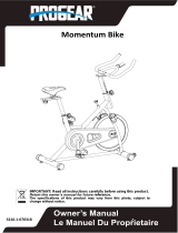
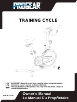
The specifications of this product may vary from this photo and are subject to change without notice.
IRONMAN, IRONMAN TRIATHLON and M-DOT are registered trademarks of World Triathlon Corporation.
This product is licensed by the World Triathlon Corporation.
OWNER’S MANUAL
Model 6102
Programmable Upright Bike

6102.1‐082515

SERVICE ------------------------------------------------------------------------ 2
LABEL PLACEMENT --------------------------------------------------------- 3
PRODUCT SAFETY ---------------------------------------------------------- 4
OVERVIEW DRAWING ------------------------------------------------------ 5
HARDWARE AND TOOLS LIST ------------------------------------------- 6
PARTS LIST -------------------------------------------------------------------- 7
ASSEMBLY --------------------------------------------------------------------- 9
COMPUTER -------------------------------------------------------------------- 18
TROUBLESHOOTING & MAINTENANCE ----------------------------- 26
WARM UP ----------------------------------------------------------------------- 27
WARRANTY -------------------------------------------------------------------- 28
FAX FORM ---------------------------------------------------------------------- 29
TABLEOFCONTENT
1

IMPORTANT: FOR NORTH AMERICA ONLY
To request product service and order
replacement parts, please call our
customer service department at:
1-844-641-7922
Monday through Friday, 8:00 AM-5:00 PM Pacific Standard Time,
or email us at: service@paradigmhw.com
Please visit our website at www.paradigmhw.com.
Please have the following information ready when requesting for service:
Your name
Phone number
Model number
Serial number
Part number
Proof of Purchase
Before returning this product to the store please contact
customer service at the contact number.
Paradigm Health & Wellness, Inc.
1189 Jellick Ave
City of Industry, CA 91748 USA
SERVICE
2

CAUTION (Model 6102)
ATTENTION (N° 6102)
(P-2) Into the
(P-1) Into the
Pedal
(P-1)
(P-2)
AVERTISSEMENT
Le poids maximum pout ce produit
est 159 kgs.
Maximum weight capacity is 350 lbs.
MADE IN CHINA / FABRIQUÉ EN CHINE
For customer assistance call:
1-844-641-7922
8 am - 5 pm PST
Mon - Sun
Pour le service a la clientèle
composer le:
1-844-641-7922
Du lundi au dimanche
8:00 h - 17 h (HNP)
LABELPLACEMENT
3

Basic precautions should always be followed, including the following safety
instructions when using this equipment. Read all instructions before using
this equipment.
1. Read all the instructions in this manual and do warm up exercises before
using this equipment.
2. Before exercising and to avoid injuring your muscles, perform warm-up
exercise for each muscle group is highly recommended. Please refer to
Warm Up section of the Owner’s Manual.
3. Please make sure all components are not damaged and in working order
before use. This equipment should be placed on a flat surface while in use.
Using a mat or other material on the ground is recommended.
4. Please wear proper clothes and shoes when using this equipment; do not
wear clothes that might catch in any part of the equipment.
5. Do not attempt any maintenance or adjustments other than those described
in this manual. Should any problems arise, discontinue use and consult
with customer service at Paradigm.
6. Caution should be taken when getting on or off the equipment. To get on,
make sure the left foot pedal is at the lowest position. Grab the stationary
handlebar firmly with both hands then place your left foot onto the left foot
pedal. Once your left foot is secured, place your right foot onto the right
foot pedal. To begin exercising, push/pull on the handrails first and then
follow with leg motion. To get off, come to a complete stop and do the
above in reverse.
7. Keep dry - do not operate in wet or moist condition.
8. Do not use the equipment outdoors.
9. This equipment is for household use only.
10. Only one person should be on the equipment at any time.
11. Keep children and pets away from the product while in use.
12. This machine is designed for adults only.
13. This product requires a minimum of 6 feet of space for safe operation.
14. If you feel any chest pains, nausea, dizziness, or short of breath, you
should stop exercising immediately and consult your physician before
continuing.
15. The maximum weight capacity for this product is 350 lbs/159 kgs.
WARNING: Before beginning any exercise program consult your
physician. This is especially important for the people who are over 35 years
old or who have pre-existing health problems. Read all instructions before
using any fitness equipment.
CAUTION: Read all instructions carefully before operating this
product. Retain this Owner’s Manual for future reference.
PRODUCTSAFETY
4

OVERVIEWDRAWING
5

HARDWARE&TOOLSLIST
6

No. Description Q’ty No. Description Q’ty
A Computer set F Crank set
A-1 Computer 1 F-1 Left crank 1
A-2 Computer Screws M5x0.8x10L 4 F-2 Right crank 1
A-3 Audio cable 1 F-3 Belt 1
B Fixed bar set F-4 Belt wheel 1
B-1 Fixed handlebar 1 F-5 Round magnet 1
B-2 Handle pulse sensor 2 F-6 Hex bolt M6x1.0x15L 4
B-3 Handle pulse cable 1 F-7 Nylon nut M6x1.0x6T 4
B-4 Screw ST4*1.41*25L 2 F-8 Crank axle 1
C Handlebar post set F-9 C-clip D22.5*D18.5*1.2T 2
C-1 Handlebar post 1 F-10 Waved washer D27*D21*0.3T 1
C-2 Upper computer cable 1 F-11 Anti-loosen nut M10*1.25*10T 2
C-3 Bolt M5*0.8*15L,8.8 2 F-12 Screw cover D26*11L 2
C-4 Screw ST4.2x1.4x15L 2 G Fixing plate for magnet set
C-5 Computer bracket 1 G-1 Fixing plate for magnet 1
D Seat post set G-2 Hex bolt M8*52L 1
D-1 Seat post 1 G-3 Nylon nut M8*1.25*8T 1
D-2 Oval cap 2 G-4 Nylon nut M6*1*6T 1
D-3 Screw M6*1*10L,8.8 1 G-5 Nylon washer D6*D19*1.5T 1
D-4 Knob M12*25L 1 G-6 Flat washer D13*D6.5*1.0T 1
E Main frame set G-7 Nut M6*1*6T 1
E-1 Main frame 1 G-8 Spring D1.0*55L 1
E-2 Bearing 2 G-9 Hex bolt M6*60L 1
E-3 Pop pin 1 H Flywheel set
E-4 Inner tube 1 H-1 Flywheel 1
E-5 Lower computer cable 1 H-2
Anti-loosen
nut 3/8"-26UNFx6.5T
2
E-6 Bolt M5x0.8x12L 1 H-3 Nut D9.5x4T 2
E-7 Sensor cable 1 H-4 C-clip 1
E-8 Electric cable 1 H-5 Flywheel axle 1
E-9 Motor 1 H-6 Fixing ring 1
E-10 Screw ST4.2*1.4*15L 2 H-7 Screw cover 1
E-11 Cable plug 1 H-8 Bearing 2
PARTLIST
7

.
No. Description Q’ty No. Description Q’ty
H-9 Small wheel 1 K-11 Bearing 1
H-10 Bearing 1 K-12 C-clip 1
H-11 One-way bearing 1 K-13 Spacer D17.8xD8.2x5.2 1
H-12 Bearing 2 L Seat adjustment set 1
I Front stabilizer set L-1 Seat 1
I-1 Front stabilizer 1 M Chain cover set
I-2 Adjustable wheel 2 M-1 Left chain cover 1
I-3 End cap 2 M-2 Right chain cover 1
I-4 Allen bolt M8*1.25*50L 2 M-3 Screw ST4.2x1.4x20L 9
I-5 Round wheel 2 M-4 Pin 2
I-6 Flat washer D16xD8.5x1.2T 8 N Screw set
I-7 Spring washer D15.4xD8.2x2T 2 N-1 Carriage bolt M8x1.25x60L 4
I-8 Domed nut M8x1.25x15L 2 N-2 Spring washer D13.2xD8.2x2T 12
I-9 Nut M10*1.5*8T 2 N-3 Flat washer D16xD8.5x1.2T 12
I-10 Bushing D22.2*D8.2*7T 4 N-4 Allen bolt M8*1.25*50L 4
J Rear stabilizer set N-5 Bolt M5x0.8x15L 2
J-1 Rear stabilizer 1 N-6 Domed nut M8x1.25x15L 4
J-2 Adjustable leveler 2 N-7 Allen bolt M8*1.25*20L 4
J-3 End cap 2 N-8 nylon nut M8*1.25*8T 1
J-4 Nut M10*1.5*8T 2 N-9 Allen screw M8*1.25*45L 1
K Idle wheel set O Handlebar cover 1
K-1 Nylon nut M8*1.25*8T 1 P Pedal set
K-2 Plastic washer D50*D10*1.0T 1 P-1 Left pedal 1
K-3 Flat washer D24*D16*1.5T 1 P-2 Right pedal 1
K-4 Plastic washer D10*D24*0.4T 1 P-3 Pedal strap 2
K-5 Fixing plate for idle wheel 1 Q Upper protective cover 1
K-6 Allen bolt M8x1.25x30L 1 R Bottle holder 1
K-7 Spring D2.2*D14*65L 1 S Computer plate 1
K-8 Plastic cover 2 T Adaptor 1
K-9 Flat washer D30*D8.2*6T 1 T1 AC Plug 1
K-10 Wave washer D21xD16.2x0.3T 1
PARTLIST
8

1. Front and Rear Stabilizer Installation
1.1 Front Stabilizer Installation.
Lift up the front part of Main Frame (E-1) and then align the Front Stabilizer (I-1) onto the front
curve of the Main Frame. From the bottom, insert 2 Carriage Bolts (N-1) through the holes. Next
place two Flat Washers (N-3), two Spring Washers (N-2) and two Domed Nuts (N-6) on top of the
Carriage Bolts (N-1). Hold the Front Stabilizer (I-1) to the Main Frame (E-1) and use the Open
Wrench 12, 13mm to tighten the Domed Nuts (N-6).
SEE NEXT PAGE for hardware pictures.
Pro Tip : You can place a solid piece of styrofoam underneath the Main Frame (E-1) to make it
easier to install the stabilizers.
1.2 Rear Stabilizer Installation.
Lift up the rear of the Main Frame (E-1) and then align the Rear Stabilizer (J-1) onto the rear
curve of the Main Frame (E-1). From the bottom, insert 2 Carriage Bolts (N-1) through the holes.
Next place two Flat Washers (N-3), two Spring Washers (N-2) and two Domed Nuts (N-6) on top
of the Carriage Bolts (N-1). Hold the Rear Stabilizer (I-1) to the Main Frame (E-1) and use the
Open Wrench 12, 13mm to tighten the Domed Nuts (N-6).
ASSEMBLY
9
Tool:
Open Wrench 12,13 mm 1PC

1.3 Adjustable Leveler Adjustment
Turn the Adjustable leveler (J-2) to the desired height.
Ensure the machine is level on the floor before use.
Proper adjustment will reduce wobbling and squeaking.
Hardware:
N-1 Carriage Bolt
M8x1.25x60L
4PCS
N-3 Flat Washer
D16xD8.5x1.2T
4PCS
N-2 Spring washer
D13.2xD8.2x2T
4PCS
N-6 Domed Nut
M8x15L
4PCS
ASSEMBLY
10

A
c
B
2. Seat Post and Seat Installation
2.1 Seat Post Installation
Turn the Round Knob (E-3) on the Main Frame (E-1) in a counterclockwise direction until it can be
pulled back. Pull back the Round Knob (E-3) and then insert the Seat Post (D-1) into the tube of
the Main Frame (E-1). Slide the Seat Post (D-1) up or down to the desired position ( see
diagram A). Lock the Seat Post (D-1) in place by releasing the Round Knob (E-3) and sliding the
Seat Post (D-1) up or down slightly until the Round Knob (E-3) "pops" down into the locked
position. Fully tighten the Round Knob (E-3) in a clockwise direction.
WARNING: When adjusting the height of seat post, the MAX line cannot be higher than
the edge of the plastic bushing.
2.2 Seat Installation
Attach Seat (L-1) onto the Seat adjustment set (L) and tighten nuts with the Open wrench
14,15mm provided (see diagram C), then slide the Seat backward and forward ( see diagram B. )
to a suitable position. Turn the Knob (D-4) clockwise to tighten.
11
ASSEMBLY
Tool:
Open Wrench 14,15 mm 1PC

A
B
3. Handlebar Post Installation
Slide the Handlebar cover (Q) onto the Handlebar Post (C-1) (see diagram A). Use the twist tie to
gently pull out the Upper Computer Cable (C-2) from the Handlebar Post (C-1) (see diagram B).
Connect it with the Lower Computer Cable (E-5) from the Main Frame (E-1) (see diagram C).
Insert Handlebar Post (C-1) onto Main Frame (E-1) and secure with four Flat Washers (N-3), four
Spring Washers (N-2) and four Allen Bolts (N-4). Use the 6mm Allen Wrench with Phillips
Screwdriver to tighten the Allen Bolts (N-4) until it’s secure.
Hardware:
N-3 Flat washer
D16xD8.5x1.2T
4PCS
N-2 Spring washer
D13.2xD8.2x2T
4PCS
N-4 Allen bolt
M8x1.25x50L
4PCS
12
ASSEMBLY
Tool:
Allen Wrench with Phillips
Screwdriver 6mm 1PC

LOWER end
UPPER end
3.1 Hand pulse cable feeding
Tie the lower end of the twist tie to the Hand Pulse Cable (B-3). Gently pull on the upper
end of the twist tie to feed the Hand pulse cable (B-3) through the hole on the front side of
Handlebar post (C-1) and up through the slot.
4 Handlebar Installation
Place the fixed Handlebar (B-1) onto the Handlebar Post (C-1), tighten with four Allen bolts (N-7),
four Spring Washers (N-2) and four Flat Washers (N-3) using the 6mm Allen Wrench with Phillips
screwdriver provided.
.
Hardware:
N-7 Allen Bolt
M8x1.25x20L
4PCS
N-3 Flat Washer
D16xD8.5x1.2T
4PCS
N-2 Spring washer
D13.2xD8.2x2T
4PCS
ASSEMBLY
13
ASSEMBLY
Tool:
Allen Wrench
6mm 1PC

4.1 Pull the Upper computer cable (C-2) and Handle pulse cable (B-3) out from the top end of
Handlebar Post (C-1). Then route both cables through the hole of Computer Plate (S). Then
tighten Computer Plate (S) with Nylon Nut (N-8) and Allen Screw (N-9) using the 6mm Allen
Wrench with Phillips screwdriver provided.
ASSEMBLY
14
Assemble Handlebar Cover (O) onto the Handlebar post (C-1) with two Bolts (N-5) by
6mm Allen wrench with Phillips screwdriver provided.
N-5 Bolt
M5x0.8x15L
2PCS
Hardware:
Hardware:
N-8 Nylon Nut
M8*1.25*8T 1PC
N-9 Allen screw
M8*1.25*45L 1PC
Tool:
Allen Wrench with Phillips
Screwdriver 6mm 1PC

5. Computer Installation
Remove 4 Computer Screws ( A-2) from the back of the Computer (A-1), use these to install the
Computer (A-1) onto the Computer Plate (S) in Step 5.2. Connect Upper Computer Cable (C-2)
into the white 9 pin port on the back of the Computer (A-1).
5.1 Connect the Computer hand pulse cable (B-3) into the back of the Computer (A-1).
5.2 GENTLY tuck the excess wire into the hole so they don’t get pinched. Attach Computer
(A-1) to the Computer Plate (S) with the 4 Computer Screws (A-2) using the 4mm Allen Wrench
provided.
6.Bottle Holder Installation
Attach the Bottle Holder (R) onto the Handlebar Post (C-1) and tighten with two Bolts (C-3) by
6mm Allen wrench with Phillips screwdriver provided.
NOTE: Bolts (C-3) are preinstalled onto handlebar post (C-1).
15
ASSEMBLY
Allen Wrench
4mm 1PC
Tool:
Allen Wrench with Phillips
Screwdriver 6mm 1PC

7. Foot Pedal Installation
Assemble the Pedal Strap (P-3) on both Left and Right Pedal (P-1),(P-2) first.
The Cranks and Pedals are marked “R” for Right and “L” for Left.
Insert the pedal shaft of the LEFT Pedal (P-1) into the threaded hole of the LEFT Crank (F-1).
Turn the pedal shaft by hand in the COUNTER- clockwise direction until snug.
Tighten the pedal shaft of Left Pedal (P-1) with the Open Wrench 14,15mm provided.
Note: DO NOT turn the left pedal shaft in the clockwise direction, doing so will
strip the
threads.
Insert the pedal shaft of the RIGHT Pedal (P-2) into the threaded hole of the RIGHT Crank (F-2).
Turn the pedal shaft by hand in the CLOCKWISE direction until snug. Tighten the pedal shaft of
Right Pedal (P-2) with the Open Wrench 14,15mm provided
ASSEMBLY
16
Tool:
Open Wrench 14,15 mm 1PC

8. Adaptor Installation
Plug one end of the Adaptor (T) into A/C plug (T-1) on the front of the Main Frame (E-1). Plug the
other end of the Adaptor (T) to the electrical wall outlet.
ASSEMBLY
17

BUTTON FUNCTION:
ON/OFF FAN
Turn the fan on or off
QUICK START
STOP
To start or stop workout
UP/DOWN
To select training mode or adjust function value
RESET
In stop mode, press the button to return to main menu.
Press and hold for 2 seconds to reboot the computer and reset all values
to 0.
ENTER
Confirm setting or selection
RECOVERY
To test heart rate recovery level.
COMPUTER
18
/
