Aquatic 103676-000-001 E160 Installation guide
- Category
- Faucets
- Type
- Installation guide

— 1 —
Installation Instructions
Domeless Acrylic Shower Stalls/Tub-Showers
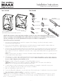
3/16” Drill Bit
3-1/2” Drill Bit
1” Drill Bit
Screw Driver Bit
#8 X 1”
Pan Head
Screws
100% Mildew
Resistant Silicone Sealant
LevelHammer
Tape Measure
Drill
Shower or Tub-Shower
Product illustration may not be representative of your unit.
Items Included Tools Needed
NOTICE: Please inspect the unit thoroughly before installation to make sure it has not been damaged during transportation.
Under no circumstances should a damaged unit be installed. Neither the manufacturer nor the distributor will be responsible for
removal or reinstallation costs should a replacement be necessary due to installation of a damaged unit.
PRE-INSTALLATION PLANNING
1. Unit must be placed within bathroom area before completion of door framing or, if preferred, studs may be omitted or
knocked-out to permit unit placement.
2. Review job print and manufacturer rough-in dimensions; verify all key dimensions against actual job conditions . Make sure
framed-in alcove is of proper size, square and plumb; check floor for levelness.
3. The blocks and/or legs attached underneath the bottom of the bath fixture are an integral part of the support system and should not
be removed. Although these blocks and/or legs need not touch for an acceptable install, this may be an indication that the unit
and/or sub-floor are out of level. Manufacturer recommends to shim, or support with foundation material, any gap under the blocks
and/or legs.
NOTE: It is a best practice in the industry to set the unit in foundation material. Industrial plaster, mortar mix or non-shrink grout are
recommended for a firmer bottom support.
4. If fire-rated alcove is required, approved finish material must be in place prior to unit installation to meet fire safety requirements
of local building code and/or FHA/HUD Minimum Property Standards.
NOTE: Finished alcove must have interior dimensions
shown on rough-in diagram to permit installation of unit.
5. Showers: Provide 6” (150mm) floor opening for 2” (50mm) IPS and drain connection.
Tub-Showers: Provide 6 x 12 (130 x 300) floor opening for 1
1
⁄2
” (40mm) drain, waste and overflow (DWO) kit.
NOTE: Be sure floor opening location matches bath fixture drain location.
6. To avoid obstruction, make sure that supply lines and valve plumbing are not strapped to studs and do not project into
alcove. Also, drain pipe must not project above floor level prior to installation.
7. Make sure all plumbing is complete and to code.
8. To prevent scuffing while installing unit, cover the entire bottom of the unit with a piece of cardboard or other protective material.
9. Fasten drain fitting to unit before installing [see manufacturer’s instructions].
NOTE: Fasteners for wood framing—1
1
⁄2” galvanized roofing nails or #10 x 1
1
⁄2” self-tapping washer head screws; for concrete
or block walls—1” concrete nails and nailing tool; for steel studs (18 ga.)—drill flanges and studs with
5
⁄32” carbide bit and use
#12 x 1” sheet metal screws.

— 2 —
Installation Instructions
Domeless Acrylic Shower Stalls/Tub-Showers
6“x12”
B
A
6“ Dia.
B
A
A
A
B
B
C
C
A
B
C
A
B
C
Note: If fire-rated alcove is required, approved finish material must be in place prior to unit installation to meet fire safety requirements of local
building codes and/or FHA/HUD Minimum Property Standards.
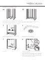
Check dimensions. Make sure framed-in alcove is of proper size, square and plumb.
For showers, refer to Diagram 1A; for tub-showers, refer to Diagram 1B.
1A 1B
2A
INSTALLATION PROCEDURE
2B
If mounting fittings — from stable reference points (back wall studs, floor) measure the locations of spout and valves. Note measurements below.
For showers, refer to Diagram 2A; for tub-showers, refer to Diagram 2B.
Mark fitting locations. (Refer to measurements from step 2.) Using a
hole saw (fine tooth or abrasive grit cutting edge), make necessary
openings for filler and valves, drilling from inside (smooth side) out.
3
Note measurements here:
Tub Filler: ________________________________
Valve: ___________________________________
Shower Arm: _____________________________
Valve: ___________________________________
(Mark dimensions only if shower arm is plumbed
within bath fixture wall area.)

— 3 —
Installation Instructions
Domeless Acrylic Shower Stalls/Tub-Showers
2
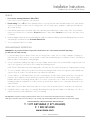
Note: Use of foundation material is highly recommended for firmer bottom support.
Prepare a foundation material mix (industrial plaster, mortar mix). Place three or four mounds on the subfloor around but away from drain hole. The
mounds should be high enough so that when the unit is set, it will cause the foundation material to displace and spread.
For showers, refer to Diagram 4A; for tub-showers, refer to Diagram 4B.
4B
5 6
8
Check for level.
INSTALLATION PROCEDURE, CONT.
4A
2
Place the unit into framing with drain fitting over and onto waste
pipe with threshold firmly on the floor.
7
Assure waste pipe protrudes well into drain fitting.
Maintain proper floor slope towards drain.
Pre-drill pilot holes. Fasten panel to framing at every stud and eight inches
vertically through nailing flange.
When other than cementitious backer board plaster is to be used, furring strips
as thick as nailing flanges are recommended for installation on studs above the
installed unit to assure walls will be flush. 100% silicone with mildew resistant
properties should be applied between the backer board and horizontal surface
of unit. Then finished wall materials can be applied.

Installation Instructions
Domeless Acrylic Shower Stalls/Tub-Showers
LITID4037 - 10042176_2020-04-15
CLEAN-UP
1. Do not remove warranty/maintenance adhered label.
Leave on unit for owner/occupant per code requirement.
2. Prevent staining. Remove all debris before plumbing leak test. Use sponge with warm water and liquid detergent. Rinse, drain and wipe
clean. Do not use abrasive cleansers such as scouring powders, steel wool, metal scrapers, sand paper or anything else that might mar,
dull or scratch the finish.
3. Plaster and latex paint may be removed with warm water, liquid detergent and brittle brush or plastic scraper. Glues, tars and enamels
may be removed with acetone or paint thinner. Do not use turpentine or laquer thinner. Do not use excessive heat or any caustic solvents
or chemicals.
4. Dull areas and light scratches may be removed by buffing with a light colored automotive rubbing compound and buffing pad. Entire unit can be
waxed with light colored automotive wax. Do not wax bottom of unit.
5. See user maintenance label for more details.
USER MAINTENANCE INSTRUCTIONS
IMPORTANT! Use only recommended cleaners and procedures described herein. Use of other materials and methods may damage
your bath fixture and void the warranty.
1. For normal cleaning: Never use abrasive cleaners such as scouring powders or pads, steel wool, scrapers, sandpaper or anything else
that could scratch or dull the surface of your unit. Instead, use warm water and liquid detergents or non-abrasive cleansers, especially those
bathroom cleaners recommended for cleaning fiberglass.
2. To keep your bath fixture sparkling clean: Apply a coat of good quality automotive paste wax or polish and buff to a high shine with a soft
cloth or towel. Repeat every six months for easier cleaning and long lasting protection.
NOTE: DO NOT WAX textured, slip-resistant standing surface of the unit bottom. This could result in greater risk of slipping and personal injury.
3. To restore a scratched or dull unit: Use an automotive polishing compound applied with a clean cotton rag. Rub scratches and dull areas
vigorously. Wipe off residues. Follow with automotive wax treatment described above.
4. To remove adhesive: Try 3-M Natural Cleaner, De-Solv-It or similar materials. If residues remain, saturate a small, white, cotton rag with
nail polish remover (naphtha or acetone) and rub vigorously until the adhesive dissolves and disappears. These solvents are highly
flammable and must be used sparingly and with caution. Do not smoke or permit others to do so. Make sure all nearby heating devices
(including pilot lights) are extinguished. Do not allow solvent to go down the drain. Make sure not to contact plastic drain grates or other
synthetic materials.
5. Rubber Mats: If you use a rubber “anti-skid” mat, make sure to remove it from the unit after each use to avoid harm to the surface finish.
6. Hard Water: Water in certain regions, if not wiped up after bathing/showering, may cause fading of some bath fixture colors. This is a
natural occurrence beyond the manufacturer’s control. (See Warranty)
CAUTION: When using any cleaning or polishing materials, make sure to read and follow all package instructions carefully. Wear
rubber gloves at all times and avoid contact with eyes, skin, clothing, rugs and furnishings. Make sure all residues are rinsed off thoroughly.
Technical Services / Service technique / Servicio
técnico
T. 1 877 GET-MAAX (1 877 438-6229)
F. 1 888 361-2045
www.maax.com
-
 1
1
-
 2
2
-
 3
3
-
 4
4


Aquatic 103676-000-001 E160 Installation guide
- Category
- Faucets
- Type
- Installation guide
Ask a question and I''ll find the answer in the document
Finding information in a document is now easier with AI
Related papers
-
Aquatic 1483SGPC-WH User manual
-
-
-
-
Aquatic 1423CM-BIHD Installation guide
-
-
-
-
Aquatic 13838BFLP Operating instructions
-
Aquatic 14832P-BIHD Operating instructions
Other documents
-
 Zenna Home 76WW Installation guide
-
Swanstone 2774CSW-AW-P-SL User manual
-
MAAX 103679-L-000-001 M260 Installation guide
-
 Laurel Mountain 6032TS1PSL064 Installation guide
-
 Foremost GFS6030LGBN-AGR User manual
-
 Aquatic Industries 1363BFSCMA-WH Installation guide
-
 Aquatic Industries 2760411R-WH Installation guide
-
 Foremost GFS603078-GML User manual
-
Foremost GFS6030LGBN-CWR User guide
-
 Aquatic Industries 4874CBW-AW Installation guide


