Page is loading ...

CANNONDALE USA
Cycling Sports Group, Inc.
1 Cannondale Way,
Wilton CT, 06897, USA
1-800-726-BIKE (2453)
www.cannondale.com
CANNONDALE EUROPE
Cycling Sports Group Europe, B.V.
Hanzepoort 27, 7570 GC, Oldenzaal,
Netherlands +41 61 4879380
servicedeskeurope@cyclingsportsgroup.com
CANNONDALE UK
Cycling Sports Group
Vantage Way, The Fulcrum,
Poole, Dorset, BH12 4NU
+44 (0)1202732288
sales@cyclingsportsgroup.co.uk
SuperSlice
Owner’s manual supplement
WWW.CANNONDALE.COM
© 2018 Cycling Sports Group
SuperSlice Owner’s Manual Supplement
134920 Rev. 1
READ THIS SUPPLEMENT AND YOUR
CANNONDALE BICYCLE OWNER’S MANUAL.
Both contain important safety information. Keep both for future reference.

1
134920 Rev 1.
ENGLISHSUPERSLICE - OWNERS MANUAL SUPPLEMENT
CONTENTS
Safety Information .............................. 2-5
Technical Information
.......................6-17
Replacement Parts...........................18-19
Notes
...................................................... 20
Cannondale Supplements
This manual is a “supplement” to your Cannondale
Bicycle Owner’s Manual.
This supplement provides additional and important
model specic safety, maintenance, and technical
information. It may be one of several important
manuals/supplements for your bike; obtain and read all
of them.
Please contact your Authorized Cannondale Dealer
immediately if you need a manual or supplement, or
have a question about your bike. You may also contact
us using the appropriate country/region/location
information. See Contacting Cannondale in this
supplement.
You can download Adobe Acrobat PDF versions of any
manual/supplement from our website:
http://www.cannondale.com
Your Authorized
Cannondale Dealer
To make sure your bike is serviced and maintained
correctly, and that you protect applicable warranties,
please coordinate all service and maintenance through
your Authorized Cannondale Dealer.
NOTICE
Unauthorized service, maintenance, or repair parts
can result in serious damage and void your warranty.
Contacting Cannondale
Cannondale USA
Cycling Sports Group, Inc.
1 Cannondale Way, Wilton CT, 06897, USA
1-800-726-BIKE (2453)
Cycling Sports Group Europe B.V
Mail: Postbus 5100
Visits: Hanzepoort 27
7570 GC, OLDENZAAL, Netherlands
Tel: +41 61 551 14 80
Fax:+31 54 151 42 40
Explicit Denitions
In this supplement, particularly important information is
presented in the following ways:
Indicates a hazardous situation which, if not avoided,
may result in death or serious injury.
NOTICE
Indicates special precautions that must be taken to
avoid damage.
THIS SUPPLEMENT MAY INCLUDE PROCEDURES
BEYOND THE SCOPE OF GENERAL MECHANICAL
APTITUDE.
Special tools, skills, and knowledge may be required.
Improper mechanical work increases the risk of an
accident. Any bicycle accident has risk of serious
injury, paralysis or death.
To minimize risk we strongly recommend that
owners always have mechanical work done by an
Authorized Cannondale retailer.

2
134920 Rev 1.
ENGLISHSUPERSLICE - OWNERS MANUAL SUPPLEMENT
SAFETY INFORMATION
YOU CAN BE YOU SERIOUSLY INJURED,
PARALYZED OR KILLED
IF YOU IGNORE WARNINGS.
Important Composites
Message
Your bike (frame and components) is made from
composite materials also known as “carbon ber.”
All riders must understand a fundamental reality
of composites. Composite materials constructed
of carbon bers are strong and light, but when
crashed or overloaded, carbon bers do not bend,
they break.
For your safety, as you own and use the bike, you
must follow proper service, maintenance, and
inspection of all the composites (frame, stem, fork,
handlebar, seat post, etc.) Ask your Cannondale
Dealer for help.
We urge you to read PART II, Section D. “Inspect For
Safety” in your Cannondale Bicycle Owner’s Manual
BEFORE you ride.
YOU CAN BE SEVERELY INJURED, PARALYZED
OR KILLED IN AN ACCIDENT IF YOU IGNORE THIS
MESSAGE.
Inspection & Crash Damage Of
Carbon Frames/Forks
AFTER A CRASH OR IMPACT:
Inspect frame carefully for damage (See PART II,
Section D. Inspect For Safety in your Cannondale
Bicycle Owner’s Manual. )
Do not ride your bike if you see any sign of damage,
such as broken, splintered, or delaminated carbon
ber.
ANY OF THE FOLLOWING MAY INDICATE A
DELAMINATION OR DAMAGE:
· An unusual or strange feel to the frame
· Carbon which has a soft feel or altered shape
· Creaking or other unexplained noises,
· Visible cracks, a white or milky color present in
carbon ber section
CONTINUING TO RIDE A DAMAGED FRAME
INCREASES THE CHANCES OF FRAME FAILURE,
WITH THE POSSIBILITY OF INJURY OR DEATH OF
THE RIDER.
Intended Use
The intended use of all models is
ASTM CONDITION 1,
High-Performance Road.
Please read your Cannondale Bicycle Owner’s
Manual for more information about Intended Use
and Conditions 1-5.

3
134920 Rev 1.
ENGLISHSUPERSLICE - OWNERS MANUAL SUPPLEMENT
Disc Brake on Road Bikes
Relative to conventional rim brakes, disc brakes are
less aected by water, do not wear or heat the rims
and therefore are more consistent. Disc brakes also
may be more powerful.
To minimize risk of injury or accidents:
· Understand that road bikes have a relatively
small tire contact patch (part of the tire that
touches the road). In order to apply the brakes
safely and eectively, you may need more or less
braking force in dierent situations. You need
to take into account various road and weather
conditions that can aect traction.
· Disc brakes are excellent, but not some kind of
magic. Take some time riding your new disc brake
road bike in lower risk circumstances to get used
to the feel and performance of the disc brakes
and tires.
YOU CAN BE SEVERELY INJURED, PARALYZED OR
KILLED IN AN ACCIDENT IF YOU IGNORE THIS
MESSAGE.
Tightening Torques
Correct tightening torque for the fasteners (bolts,
screws, nuts) on your bicycle is very important to your
safety. Correct tightening torque for the fasteners is
also important for the durability and performance of
your bicycle. We urge you to have your Dealer correctly
torque all fasteners using a torque wrench. If you decide
to torque fasteners yourself always use a torque wrench.
Find Tightening Torque Information :
The wide range of bicycle models and components
used means that a listing of tightening torque would
be out of date by the time it was published. Many
fasteners should be installed with a thread locking
adhesive such as Loctite®.
To determine correct tightening torque and any
adhesive application for a fastener we ask you to
check:
• Many components are marked. On-product
marking is becoming common.
• Torque specs in the component manufacturers
instructions shipped with your bicycle.
• Torque specs listed on the websites of
component manufacturers.
• With your Dealer. Dealers have access to
current data and have experience with correct
torque for most fasteners.
The following symbols are used in this manual:
Symbol Name Description
NGLI-2
NGLI-2 synthetic grease Apply NGLI-2 synthetic grease.
CRB-GEL
Carbon Gel Apply carbon gel (friction paste) KF115/
2
Medium-strength
removable thread lock
Apply Loctite 242 (blue) or equivalent.

4
134920 Rev 1.
ENGLISHSUPERSLICE - OWNERS MANUAL SUPPLEMENT
DO NOT RIDE ON THE AERO HANDLEBAR
EXTENSIONS IN TRAFFIC OR ON DIFFICULT
ROADS.
Ride on the aero handlebar extensions only when
the road is clear of trac and hazards and you have
a long line of sight.
When using the extensions understand that you
are compromising steering and braking in favor
of speed. If you need to take evasive steering or
braking action while on the extensions you could
have an accident, with risk of serious injury, paralysis
or death.
Aerodynamic handlebars and extensions are a
design trade-o which positions you further
forward than on a conventional road bike, so:
■ Overly hard use of the front brakes will pitch you
forward, o the bike, more easily.
■ Rear braking performance will not equal that of
a conventional road bike.
When braking hard on any bike, including time trial
or triathalon, you must shift weight back to allow
front brake use without pitching yourself forward,
o the bike. Shifting weight back allows more rear
braking eect before the rear wheel begins to skid
when braking hard, or braking on a steep downhill.
See Part 1, Section 4C. of your Cannondale Bicycle
Owner’s Manual.
Aerodynamic handlebars and extensions are
intended for racing and competition in time trial and
triathalon and are poorly suited for riding in cities or
congested urban areas where conicts with cars will
frequently require panic braking.
Aerodynamic Handlebars
Aerodynamic or “Triathlon” handlebar extensions are
tted to some triathlon or racing bikes. They are also
added by customers. Understand that when riding
on these extensions your steering and braking are
adversely aected. When on the extensions, most riders
nd it hard to look back over their shoulder without
swerving, inadvertently steering. Some riders nd it
harder to move their head/neck to see forward. Be sure
to practice riding with aero handlebar extensions on
hazard and trac free roads. Practice the transition from
having your hands on the extensions to having your
hands on the regular handlebars and brake levers.
Lower/ forward
on extensions
extensions
brake levers
AERODYNAMIC
CONVENTIONAL ROAD

5
134920 Rev 1.
ENGLISHSUPERSLICE - OWNERS MANUAL SUPPLEMENT
Trainers
If you ride a trainer that requires removal of the front
wheel and clamps the fork dropouts: Be sure your fork
quick release is tight! Relative movement will wear parts,
weaken and damage your bike.
If you ride a trainer that holds the bike up by clamping
the rear quick release between two cones: Take o the
nice, lightweight quick release that came with your
bike. Substitute a heavy, classic all steel quick release
and clamp it tight! Relative movement will wear parts,
weaken and damage your bike. Note that many modern
quick releases will not t the clamping cones in this kind
of trainer because their shapes are incompatible.
For thru axles, make sure you follow the trainer
manufacturer instructions for the use of any required
adapters
Be particularly cautious with a carbon frame or fork.
Carbon is relatively soft, not abrasion resistant. If there is
any relative movement, carbon will wear quickly.
If you ride a trainer a lot, consider using an old bike:
Corrosion from sweat will take it’s toll. Weight is
irrelevant. Save wear on your expensive components.
Ask you dealer for help with trainers, the right one
and the correct way to use it.
NOTICE
TRAINERS - Improperly mounting a bike in a trainer,
or using one that is not compatible with your
particular bike frame can cause serious damage.
WATER BOTTLES - An impact, crash, or loose bottle
cage can result in damage to your frame.
This kind of damage is not covered by the Cannondale
Limited Warranty.
Water Bottles
Side impacts to a water bottle or cage can result in
damage threaded inserts due to the leverage on a very
small area. In a crash, certainly the last thing you should
be worried about is saving the threaded inserts in your
frame. However, when you are storing or transporting
your bike, take steps to prevent situations where a water
bottle may be hit or bumped by a strong force that
would cause damage. Remove bottle and cage when
you are packing your bike for travel.
Periodically check the attachment of the bottle cage;
tighten the cage bolts if necessary. Don’t ride with a
loose bottle cage. Riding with loose cage bolts can
produce a rocking motion or vibration of the attached
cage. A loose cage will damage the insert and possibly
lead to the inserts to pull out.
It may be possible to repair a loose insert, or install
another insert only if the frame is undamaged.
Replacement requires the use of a special tool. If you
notice damage to the threaded insert, please ask your
Cannondale Dealer for help.
Building Up A Frame Set
Before building up a frame set, consult with your
Cannondale Dealer and the component manufacturers,
and discuss your riding style, ability, weight, and interest
in and patience for maintenance.
Make sure the components chosen are compatible with
your bike and intended for your weight and riding style.
Generally speaking, lighter weight components have
shorter lives. In selecting lightweight components, you
are making a trade-o, favoring the higher performance
that comes with less weight over longevity. If you
choose more lightweight components, you must inspect
them more frequently. If you are a heavier rider or have a
rough, abusive or “go for it” riding style, buy heavy duty
components.
Read and follow the component manufacturers
warnings and instructions.

6
134920 Rev 1.
a
1
2
3
4
5
b
c
7
6
2 N·m
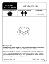
ENGLISHSUPERSLICE - OWNERS MANUAL SUPPLEMENT
TECHNICAL INFORMATION
Item Specication
Head Tube UPR: 1 1/8 In., LWR: 1 1/8 In.
Bottom Bracket: Type/ Width PF30A / 73mm
Front Derailleur Braze-On
Seat Post: Dia./Binder Superslice Seatpost / Integrated
Min. Seat Post Insert
100mm
Tire Size/ Max. Tire Width
700X25c
Front Tire Min. Clearance
6mm (See page 20)
Brakes: Mount Type/Dia. Flat Mount: 160mm or 140mm
Axles: Type/Length
FRONT: Bolt Type; 12mm Thru-Axle, 122mm M12*P1.0, Thread
Length: 11mm, Cone Shape Head.
REAR: Bolt Type; 12mm Thru-Axle, 167mm, M12*P1.0, Thread Length:
11mm, Cone Shape Head.
Intended Use
ASTM CONDITION 1,
High-Performance Road
MAX. WEIGHT LIMIT: Lbs/Kg
Total (Rider+All Equipment): 285/129
Head Tube
1. Compression Ring
3. Bearing, Upper
3. Fork Steerer
4. Head Tube Cap
5. Bearing, Lower
6. Screws
7. Seal
a. Compression Insert
(non-removable)
b. Crown Race (integrated)
c. Front Brake Housing
passage
Frame Specication

7
134920 Rev 1.
A
B
C
D
G
O
75mm
M
L
N
E
K
J
P
Q
R
S
I
H
cm 50 52 54 56 58
A 51.8 53.6 55.4 57.8 59.7
B 51.5 52.9 54.1 56.4 57.7
C 71.5° * * * *
D
1
77.0° * * * *
E 75.9 77.9 79.9 81.9 83.9
F 5.6 7.7 9.8 11.9 14
G 99.7 101.3 102.7 105.2 106.7
H 59.4 61 62.4 64.9 65.4
I 41.4 * * * *
J 7.3 * * * *
K 26.9 * * * *
L 4.8 * * * *
M 6.4 * * * *
N 46.5 48.5 50.4 52.4 54.4
O 40.8 41.7 42.5 44.3 45.1
P 53 55 57 59 61
Q 62.3 64.3 66.3 68.3 70.3
R 43.9 45.1 46.4 47.6 48.9
S
2
53.1 54.3 55.6 56.8 58.1
All Specications subject to change without notice.
* Indicates same.
1
Measurement taken at seat post head mid-point. The range is plus or minus 1.2 degrees. See “Seat Post, Seat Tube Angle”
2
Measurement inuenced by specic installed stem length (60mm, 90mm, 120mm).
ENGLISHSUPERSLICE - OWNERS MANUAL SUPPLEMENT
A Seat Tube Length
B Top Tube Horizontal
C Head Tube Angle
D Seat Tube Angle
E Standover
F Head Tube Length
G Wheelbase
H Front Center
I Chain Stay Length
J Bottom Bracket Drop
K Bottom Bracket Height
L Fork Rake
M Trail
N Stack
O Reach
P Pad Stack lowest
Q Pad Stack highest
R Pad Reach shortest
2
S Pad Reach longest
2
Dimensions = (centimeter)
Geometry

8
134920 Rev 1.
4 N·m
2 N·m
1
a
2
3
CK3027U00OS
CK3087U00OS
2
2
1
2 N·m
CK3057U00OS
1
2
a
2
NGLI-2
ENGLISHSUPERSLICE - OWNERS MANUAL SUPPLEMENT
To replace:
Remove the rear axle.
Remove the mounting screws and remove the old
hanger from the dropout. Clean the area around the
dropout and inspect the frame carefully for any cracks or
damage. If you nd damage have the frame inspected
by your Cannondale Dealer .
If the dropout is un-damaged, apply a light lm of
bike grease to both sides of the dropout. This will help
minimize any noise or “creaking” that might result from
very slight movement between the dropout and hanger
during movement of the derailleur.
Slide the new hanger onto the dropout. Apply Loctite
to the screw threads and tighten to the specied torque.
Rear Derailleur Mount Front Derailleur Mount
1. RD Hanger
2. Screw
a. Frame cable/wire exit
1. FD Hanger
2. Screw
3. FD Cable Stop
a. Frame cable/wire
exit
Serial Number
The serial number located on the bottom bracket. It
is a 7-character barcode (1). Use this serial number to
registration your bike. See your Cannondale Bicycle
Owner’s Manual for more information on warranty
registration.
www.cannondale.com/registerbike/

9
134920 Rev 1.
73mm
7mm
39.0 mm
34.0 mm
1
2
3
30 mm
42 mm
46 mm
PF30A
1. BB Shell
2. PF30 Cup
3. BB30 Bearing
ENGLISHSUPERSLICE - OWNERS MANUAL SUPPLEMENT
Maintenance
In general, you should inspect the condition of the
bearings annually (at a minimum) or anytime the crankset
assembly is disassembled , serviced, or if a problem is
indicated.
To inspect, when the crankset is removed, rotate the inner
bearing race of both bearings; rotation should be smooth,
and quiet. Execesssive play, roughness or corrossion
indicates a damaged bearing.
Removal
To avoid serious damage to the frame, it is important to
remove bearing systems very carefully using proper tools
indicated by the manufacture’s service instructions. Make
sure the bearings(cup or adpter parts) are driven out
squarely and evenly from inside the shell!!! Do not pry
components from shell.
Replacement
PressFit BB30 bearings are not removable from the
adapters or cup systems that are pressed into the frame
bottom bracket shell. Therefore, damaged bearings
must be removed and replaced as new entire sets. Before
installing any new bearing units into the shell, thoroughly
clean the inside surface of the bottom bracket shell with a
clean dry shop towel. Also, make sure both bearing units
and the BB shell surfaces are clean and dry. Do not apply
grease to either.
Follow the manufacture’s instruction for assembly and
installation of the bearing system. Use a headset press
such as Park Tool HHP-2. See http://www.parktool.com/
product/bearing-cup-press-HHP-2 Select appropriate press
and adapters to ensure that force is only applied to the
cup and not the bearing inside. Press until the both cup
anges are mated to the BB shell edge.
NOTICE
Consult with your Cannondale Dealer on the quality and
compatibilty of any proposed replacement component.
Make sure the PRESSFIT BB30 system is intended for use
with with a 46 mm I.D. BB shell. Conrm acutal part
dimensions with a micrometer.
Do not use chemical solvents to clean. Do not remove
frame material or use surfacing tools on bottom bracket
shell.
Frame damage, caused by improper components,
component installation or removal is not covered by
your warranty.
Bottom Bracket - PF30A, 73mm

10
134920 Rev 1.
75.8
78.2
77.0
ENGLISHSUPERSLICE - OWNERS MANUAL SUPPLEMENT
Seat Post
Maintenance
Periodically, remove the seat post and the clamp
assembly to clean, inspect for damage and re-new the
application of grease and carbon gel.
Removal
To remove the seat post, use a 4mm Allen key to turn
the wedge bolt counter-clockwise to loosen it. When
bolt is loose simply lift the seat post up out of the seat
tube. Then lift out the wedge assembly out of the frame
socket.
Installation
Before inserting the seat post into the frame, use a
clean shop towel to wipe out any residual carbon gel
paste from the inside the seat tube. Do not use any
spray cleaners or solvents. Apply fresh carbon friction
gel to the seat post and place a little bit inside the seat
tube. Clean the wedge assembly and lightly grease
the parts. Insert the loosened asembly into the frame,
then carefully insert the seat post into the frame. Set
the saddle height, and tighten the clamp bolt to the
specied torque with a torque wrench.
Insert Limit & Sizing a
Seat Post
The minimum insert depth the seat post must be
inserted into the frame is 100mm. This length is marked
by a line on the seat post.
The total length of seat post that may be inserted will
vary with the frame size and should be checked in each
frame. A large size frame will accomodate more seat
post length than a smaller size frame.
To check the depth, carefully slide a seat post into the
frame until it stops; then lift it up 5mm.
NOTICE
A seat post should not be bottomed out inside the
frame at any time. Have your Cannondale Dealer size
the seat post appropriately.
If the seat post must be cut, use a cutting guide and a
carbon saw blade. Lightly sand the edges of the cut seat
tube with light sandpaper. Re-mark the minimum insert
line on the post.
THE SEAT POST MUST ONLY BE CUT BY A
PROFESSIONAL BIKE MECHANIC. Incorrectly
cutting the seat post can result in damage leading
to an accident.
Seat Tube Angle
The eective seat tube angle recorded in the geometry
chart is measured to the seat post head midpoint. The
saddle mounting clamp can be moved forward and
backward on the seat post head, resulting in a range of
eective seat tube angles as shown

11
134920 Rev 1.
100mm
12 N·m
4mm
CK0077U00OS
5mm
4 N·m
CK0037U00OS
100mm
CRB-GEL
CRB-GEL
NGLI-2
ENGLISHSUPERSLICE - OWNERS MANUAL SUPPLEMENT
For more information about carbon ber seat posts, see also “Care
and Maintenance of Carbon Fiber Seat Posts” in your Cannondale
Bicycle Owner’s Manual.
SEAT POST
SEAT BINDER
Suggested Tools:
Park Tool SG-7.2
Park Tool CSB-1
If post is cut,
the line must be
re-marked.
Saddle poisiton
adjust (fore/aft).
Minimum Insert
Maximum Insert
Maximum Depth
Apply
carbon
gel

12
134920 Rev 1.
6 N-m
1
9
10
11
12
13
7
8
5
6
a
b
c
6 N-m
3
2
4
2
2
ENGLISHSUPERSLICE - OWNERS MANUAL SUPPLEMENT
1. Shroud
2. Grommet
3. Plug
4. Screw
5. Stem Top Cover
6. Screw
7. Fork Top Cap
8. Top Cap Bolt
9. Stem
10. Handle Bar
11. Stem Top Plate
12. Stem Washer
13. Stem Clamp Bolts
Assembled View
Exploded View
Handlebar/Stem

13
134920 Rev 1.
STK
BLT
15mm
9 N-m
1
2
3
4
3
4
2
ENGLISHSUPERSLICE - OWNERS MANUAL SUPPLEMENT
Arm Pad Spacers/Bolt Length
Pad Stack Change - STK Correct Bolt Length - BLT
Number of
15mm Spacers (2)
Bridge (1)
0 mm 35mm 0 No
15mm 50mm 1 Yes
30mm 65mm 2 Yes
45mm 80mm 3 Yes
60mm 95mm 4 Yes
75mm 110mm 5 Yes
90mm 125mm 6 Yes
Use the correct bolt lengths. Always clean and apply Loctite 242 to bolt threads. Tighten to the specied torque .
Pad Stack

14
134920 Rev 1.
Pad Y
Pad X
Extension + Pad = 26.5mm
Bridge = 3mm
Spacer = 15mm
Handlebar = 11mm
Stem = 26.2mm
ENGLISHSUPERSLICE - OWNERS MANUAL SUPPLEMENT
Instructions:
1. Choose the frame reach of your frame size from the “Frame Reach”
row.
2. Look down to nd one or more Pad X that can t you.
3. Note the stem length(s) and pad position(s) that can t you.
Frame Size (cm)
50 52 54 56 58
Frame Reach (mm)
392 404 417 429 442
Pad X (mm)
60 Stem = 62.5
90 Stem = 92.5
120 Stem = 122.5
60 Pad Rear, Pad Forward 439, 471 451. 483 464, 496 476, 508 489, 521
90 Pad Rear, Pad Forward 469, 501 481, 513 494, 526 506, 538 519, 551
120 Pad Rear, Pad Forward 499, 531 511, 543 524, 556 536, 568 549, 581
Instructions:
1. Find your “Pad Y” in one or more places in this table.
2. Note the combination(s) of frame(s) and no. spacers that can t you.
3. Take your frame size(s) to Pad X table below.
Frame Size (cm)
50 52 54 56 58
Frame Stack (mm)
465 485 505 525 545
Pad Y (mm)
NO. SPACERS BRIDGE
0 NO 530 550 570 590 610
1 YES 548 568 588 608 628
2 YES 563 583 603 623 643
3 YES 578 598 618 638 658
4 YES 593 613 633 653 673
5 YES 608 628 648 668 688
6 YES 623 643 663 683 703

15
134920 Rev 1.
ENGLISHSUPERSLICE - OWNERS MANUAL SUPPLEMENT
Chart : Pad X, Pad Y
Note: This is the same data as Pad X and Pad Y tables (previous page). Here, the information is arranged semi-graphically to
show overlapping Pad Y values possible with dierent frame sizes & component combinations.
Instructions:
1. Enter chart with your Pad Y (left column).
2. Read across to nd Pad X. Note: more than one frame and stem combination can give the same Pad X.
3. Refer to Table above for frame, stem & spacers needed to reach your Pad X, Y.
Frame Size (cm)
50 52 54 56 58
Stem Length (mm) 60 90 120 60 90 120 60 90 120 60 90 120 60 90 120
Pad Y (mm)
Pad X (mm) (Pad Rear, Pad Forward)
703
489, 521 519, 551 549, 581
688
489, 521 519, 551 549, 581
683
476, 508 506, 538 536, 568
673
489, 521 519, 551 549, 581
663
464, 496 494, 526 524, 556
658
489, 521 519, 551 549, 581
653
476, 508 506, 538 536, 568
648
464, 496 494, 526 524, 556
643
451, 483 481, 513 511, 543 489, 521 519, 551 549, 581
638
476, 508 506, 538 536, 568
633
464, 496 494, 526 524, 556
628
451, 483 481, 513 511, 543 489, 521 519, 551 549, 581
623
439, 471 469, 501 499, 531 476, 508 506, 538 536, 568
618
464, 496 494, 526 524, 556
613
451, 483 481, 513 511, 543
610
489, 521 519, 551 549, 581
608
439, 471 469, 501 499, 531 476, 508 506, 538 536, 568
603
464, 496 494, 526 524, 556
598
451, 483 481, 513 511, 543
593
439, 471 469, 501 499, 531
590
476, 508 506, 538 536, 568
588
464, 496 494, 526 524, 556
583
451, 483 481, 513 511, 543
578
439, 471 469, 501 499, 531
570
464, 496 494, 526 524, 556
568
451, 483 481, 513 511, 543
563
439, 471 469, 501 499, 531
550
451, 483 481, 513 511, 543
548
439, 471 469, 501 499, 531
530
439, 471 469, 501 499, 531

16
134920 Rev 1.
FB
RB
FB
RB
ENGLISHSUPERSLICE - OWNERS MANUAL SUPPLEMENT
wire
connector
wire
connector
wire
NOTICE
Ensure adequate slack through
the stem port to allow slight
movement without binding of
the cables and wires.
The shroud grommets help
reduce chang of cables
passing into the frame.
For mechnical shifting, control wires exiting
the bar extension rear enter the top tube
shroud with the plugs removed.
Internal Routing
This illustration is a simplied view of the
internal handlebar system routing.
DO NOT modify, cut, drill, or
enlarge existing openings in the
frame, handlebar, stem, or other
parts. Installation of shift systems
(mechanical, wires, connectors, and
controls), must be tted in available
space without alteration.
FB - Front Brake Hose
RB - Rear Brake Hose

17
134920 Rev 1.
Shimano
SM-EW90A
Shimano
BT-DN110
2
3
4
5
1
6
CK3097U00OS
M5 x 12mm
ENGLISHSUPERSLICE - OWNERS MANUAL SUPPLEMENT
Secured to saddle rail.
1. Battery
2. Battery Mount
3. Mounting Screw
4. Cable Ties
5. Control Wire
6. Control Junction 3-port
Control wires exiting the seat
post interior
Ensure adequate control
wire slack to avoid accidental
disconnections during seat post
adjustment.
The battery is rst secured to the
mounting bracket with cable ties.
The battery and mount is then
secured to the frame cap.
Shimano Di2 - Battery

18
134920 Rev 1.
F
D
E
B
A
G
C
H
J
K
I
O
2
4 N·m
2
2 N·m
2
2 N·m
2
2 N·m
2
4 N·m
M
N
122mm M12x1
167mm M12x1
STK
15mm
Q
2
9 N·m
2 N·m
2
6 N·m
2
P
BLT
P
6 N·m
2
6 N·m
2
ST
TC
BM
L
CRB-GEL
ID Part Number Description
A CK0037U00OS Superslice Seatpost
B CK0077U00OS Superslice Seatpost Binder
C CK3137U00OS Superslice Top Tube Cable Guide
D CK3027U00OS Superslice Front Derailleur Mount
E CK3087U00OS Superslice Front Derailleur Cable Stop
F CK3057U00OS Derailleur Hanger TA ST SS 014
I KP197/SRM PF30 Bottom Bracket Cups & Bearings
J K22037 BB30 Bearing Blue (QTY=24)
K KB6180/ BB30 Bearing Blue (QTY=2)
L K34059 SuperSlice Headtube Cap.
M CK8027U00OS Rear Thru Axle Super Slice
N CK8067U00OS Front Thru Axle Super Slice
ID Part Number Description
BM CK3097U00OS Di2 Bracket (battery)
O CK3097U00OS Superslice Bottom Bracket Cover
G
CK3127U1050 Superslice Headtube Shroud BLK 50
CK3127U1052 Superslice Headtube Shroud BLK 52
CK3127U1054 Superslice Headtube Shroud BLK 54
CK3127U1056 Superslice Headtube Shroud BLK 56
CK3127U1058 Superslice Headtube Shroud BLK 58
CK3127U8050 Superslice Headtube Shroud REP 50
H
CK3127U8052 Superslice Headtube Shroud REP 52
CK3127U8054 Superslice Headtube Shroud REP 54
CK3127U8056 Superslice Headtube Shroud REP 56
CK3127U8058 Superslice Headtube Shroud REP 58
ENGLISHSUPERSLICE - OWNERS MANUAL SUPPLEMENT
Replacement Parts - Frame/Fork

19
134920 Rev 1.
F
D
E
B
A
G
C
H
J
K
I
O
2
4 N·m
2
2 N·m
2
2 N·m
2
2 N·m
2
4 N·m
M
N
122mm M12x1
167mm M12x1
STK
15mm
Q
2
9 N·m
2 N·m
2
6 N·m
2
P
BLT
P
6 N·m
2
6 N·m
2
ST
TC
BM
L
CRB-GEL
ID Part Number Description
TC KP476/ Kit, Preload Cap, Super Slice
ST
CK0097U0020 Superslice Stem 120mm
CK0097U0060 Superslice Stem 60mm
CK0097U0090 Superslice Stem 90mm
P CK0107U00OS Superslice Stack Spacers
Q CK0117U00OS Superslice Base Bars - 380mm
ENGLISHSUPERSLICE - OWNERS MANUAL SUPPLEMENT
Replacement Parts - Handlebar/Stem
/