Page is loading ...


Table of Contents
i
SAFETY PRECAUTIONS
IMPORTANT SAFETY INFORMATION .......................................... 1
SCAN TOOL CONTROLS
CONTROLS AND INDICATORS ..................................................... 2
DISPLAY FUNCTIONS .................................................................... 3
BATTERY REPLACEMENT ............................................................. 5
USING THE SCAN TOOL
CODE RETRIEVAL PROCEDURE .................................................. 6
THE SYSTEM MENU ........................................................................ 11
VIEWING OEM ENHANCED DTCs (except Ford/Mazda) .............. 11
VIEWING OEM ENHANCED DTCs (Ford/Mazda only) .................. 12
VIEWING ABS DTCs ........................................................................ 14
VIEWING SRS DTCs ....................................................................... 15
NETWORK TEST ............................................................................. 16
ERASING DIAGNOSTIC TROUBLE CODES (DTCs) .................... 19
LIVE DATA MODE
VIEWING LIVE DATA ....................................................................... 21
CUSTOMIZING LIVE DATA (PIDs) ................................................. 22
RECORDING (CAPTURING) LIVE DATA ........................................ 23
LIVE DATA PLAYBACK ................................................................... 26
ADDITIONAL TESTS
THE MAIN MENU .............................................................................. 28
SYSTEM/ACTUATOR TESTS ......................................................... 28
SYSTEM TEST MENU ..................................................................... 77
VIEWING VEHICLE INFORMATION ............................................... 80
RESETTING THE OIL MAINTENANCE LIGHT .............................. 81
USING THE DLC LOCATOR ........................................................... 83
BATTERY RESET ............................................................................ 83
BATTERY/ALTERNATOR MONITOR ............................................. 85
VIEWING DRIVE CYCLE PROCEDURES ...................................... 88
STEERING ANGLE SENSOR (SAS) CALIBRATION ..................... 89
VIEWING THE FIRMWARE VERSION ........................................... 90
THE TOOL LIBRARY ....................................................................... 90
ADJUSTMENTS, SETTINGS AND LANGUAGE ............................ 93
OBD UPDATER ................................................................................ 95
USING SCAN TOOL MEMORY
VIEWING DATA IN MEMORY ......................................................... 96
TROUBLESHOOTING
TROUBLESHOOTING ................................................................... 97
WARRANTY AND SERVICING
LIMITED 90 DAY WARRANTY ......................................................... 97
SERVICE PROCEDURES ............................................................... 98

Safety Precautions
IMPORTANT SAFETY INFORMATION
For technical questions, please call 1-888-866-5797.
1
IMPORTANT SAFETY INFORMATION
Read all safety warnings and all instructions.
Failure to follow the warnings and instructions may result in electric
shock, fire and/or serious injury.
Save all warnings and instructions for future reference.
1. Operating a vehicle indoors CAN KILL YOU IN MINUTES. Engine
exhaust contains carbon monoxide. This is a poison you cannot see
or smell. NEVER operate vehicle inside a home or garage, EVEN IF
doors and windows are open. Only use OUTSIDE and far away from
windows, doors, and vents.
2. People with pacemakers should consult their physician(s) before use.
Electromagnetic fields in close proximity to heart pacemaker could
cause pacemaker interference or pacemaker failure. Caution is
necessary when near coil, spark plug cables, or distributor of running
engine. Engine should be off during distributor adjustment.
3. Keep clothing, hair, hands, tools, test equipment, etc. away from all
moving or hot engine parts.
4. Put the transmission in PARK (for automatic transmission) or
NEUTRAL (for manual transmission) and make sure the parking
brake is engaged.
5. Put blocks in front of and behind the drive wheels.
6. Read vehicle service manual before inspecting, maintaining, or
repairing a vehicle.
7. Wear ANSI-approved safety goggles.
8. Never leave the vehicle unattended while running tests.
9. Keep a fire extinguisher suitable for gasoline/chemical/electrical fires
nearby.
10. Don’t connect or disconnect any test equipment while the ignition is
on or the engine is running.
11. This product is not a toy. Keep it out of reach of children.
12. Keep the Scan Tool dry, clean, free from oil, water or grease. Use a
mild detergent on a clean cloth to clean the outside of the Scan Tool,
when necessary.
13. The warnings, precautions, and instructions discussed in this
instruction manual cannot cover all possible conditions and situations
that may occur. It must be understood by the operator that common
sense and caution are factors which cannot be built into this product,
but must be supplied by the operator.
SAVE THESE INSTRUCTIONS.

Scan Tool Controls
CONTROLS AND INDICATORS
2 For technical questions, please call 1-888-866-5797.
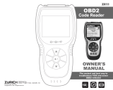
CONTROLS AND INDICATORS
Figure 1. Controls and Indicators
See Figure 1 for the locations of items 1 through 16, below.
1. ERASE button - Erases Diagnostic Trouble Codes (DTCs), and
“Freeze Frame” data from the vehicle’s computer, and resets Monitor
status.
2. SYSTEM MENU button – When pressed, displays the System
Menu.
3. DTC/FF button - Displays the DTC View screen and/or scrolls the
LCD display to view DTCs and Freeze Frame data.
4. POWER/LINK button - When not connected to a vehicle,
turns the Scan Tool “On” and “Off” (press and hold for 3 seconds).
When connected to a vehicle, links the Scan Tool to the vehicle’s
PCM.
5. M button – When pressed, displays the Main Menu.
6. LD button – When pressed while linked to a vehicle, places the Scan
Tool in Live Data mode.
7. UP button – When in MENU mode, scrolls UP through the menu
options. When LINKED to a vehicle, scrolls UP through the current
display screen to display additional data.
8.
ENTER button - When in MENU mode, confirms the selected
option or value.

Scan Tool Controls
DISPLAY FUNCTIONS
For technical questions, please call 1-888-866-5797.
3
9. DOWN button - When in MENU mode, scrolls DOWN through
the menu options. When LINKED to a vehicle, scrolls DOWN through
the current display screen to display additional data.
10. Left Option Button - Selects the associated option shown on the
display (Yes/No, Previous/Next, etc).
11. Right Option Button - Selects the associated option shown on the
display (Yes/No, Previous/Next, etc).
12. GREEN LED - Indicates that all engine systems are running normally
(all Monitors on the vehicle are active and performing their diagnostic
testing, and no DTCs are present).
13. YELLOW LED - Indicates there is a possible problem. A “Pending”
DTC is present and/or some of the vehicle’s emission monitors have
not run their diagnostic testing.
14. RED LED - Indicates there is a problem in one or more of the vehicle’s
systems. The red LED is also used to show that DTC(s) are present.
DTCs are shown on the Scan Tool’s display. In this case, the
Malfunction Indicator (“Check Engine”) lamp on the vehicle’s
instrument panel will light steady on.
15. Display - Color LCD display shows menus and submenus, test
results, Scan Tool functions and Monitor status information. See
DISPLAY FUNCTIONS, following, for more details.
16. CABLE - Connects the Scan Tool to the vehicle’s Data Link
Connector (DLC).
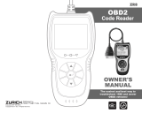
DISPLAY FUNCTIONS
Figure 2. Display Functions
See Figure 2 for the locations of items 1 through 14, below.
1. I/M MONITOR STATUS field - Identifies the I/M Monitor status area.

Scan Tool Controls
DISPLAY FUNCTIONS
4 For technical questions, please call 1-888-866-5797.
2. Monitor icons - Indicate which Monitors are supported by the vehicle
under test, and whether or not the associated Monitor has run its
diagnostic testing (Monitor status). A solid green icon indicates the
associated Monitor has completed its diagnostic testing. A flashing
red icon indicates that the vehicle supports the associated Monitor,
but the Monitor has not yet run its diagnostic testing.
3. Vehicle icon – When visible, indicates that the Scan Tool is being
powered through the vehicle’s DLC connector.
4. Link icon - When visible, indicates the Scan Tool is
communicating with the vehicle’s computer.
5. Computer icon - When visible, indicates the Scan Tool is linked
to a personal computer.
6. Scan Tool Internal Battery icon - When visible, indicates the
Scan Tool batteries are “low” and should be replaced. If the batteries
are not replaced when the battery symbol is "on", all 3 LEDs will
light to warn that the batteries need replacement. No data is displayed
on screen when all 3 LEDs are lit.
7. DTC Display Area - Displays the Diagnostic Trouble Code (DTC)
number. Each fault is assigned a code number that is specific to that
fault.
8. Code Number Sequence - The Scan Tool assigns a sequence
number to each DTC that is present in the computer’s memory,
starting with “1.” This number indicates which code is currently
displayed. Code number “1” is always the highest priority code, and
the one for which “Freeze Frame” data has been stored.
If “1” is a “Pending” code, there may or may not be “Freeze
Frame” data stored in memory.
9. Code Enumerator - Indicates the total number of codes retrieved
from the vehicle’s computer.
10. Test Data Display Area - Displays DTC definitions, Freeze Frame
data and other pertinent test information messages.
11. SYSTEM icon - Indicates the system with which the code is
associated:
MIL icon ABS icon SRS icon
12. FREEZE FRAME icon - Indicates that there is Freeze Frame data
from “Priority Code” (Code #1) stored in the vehicle’s computer
memory.
13. Code type - Indicates the type of code being displayed; Generic
Stored, Generic Pending, Generic permanent, etc.

Scan Tool Controls
BATTERY REPLACEMENT
For technical questions, please call 1-888-866-5797.
5
BATTERY REPLACEMENT
Replace batteries when the battery symbol is visible on display and/or
the 3 LEDS are all lit and no other data is visible on screen.
1. Locate the battery cover on the back of the Scan Tool.
2. Slide the battery cover off (use your fingers).
3. Replace batteries with three AA-size batteries (for longer life, use
Alkaline-type batteries).
4. Reinstall the battery cover on the back of the Scan Tool.
Adjustments
The first time the Scan Tool is turned on, you must select the desired
display language (English, French or Spanish) and unit of measurement
(Standard or metric) as follows:
1. Press and hold POWER/LINK to turn the Scan Tool “ON.”
n The Select Language screen displays.
2. Select the desired display language, then press ENTER .
n The Select Unit screen displays.
3. Select the desired unit of measurement, then press ENTER .
n The Firmware Version screen displays.
After the initial language and unit of measurement selections
are performed, these, as well as other settings, can be changed
as desired. Proceed to “ADJUSTMENTS, SETTINGS AND
LANGUAGE” on page 93 for further instructions.

Using the Scan Tool
CODE RETRIEVAL PROCEDURE
6 For technical questions, please call 1-888-866-5797.
CODE RETRIEVAL PROCEDURE
Never replace a part based only on the
DTC definition. Each DTC has a set of testing procedures,
instructions and flow charts that must be followed to
confirm the location of the problem. Always refer to the
vehicle's service manual for detailed testing instructions.
Check your vehicle thoroughly before performing
any test.
ALWAYS observe safety precautions whenever
working on a vehicle.
1. Turn the ignition off.
2. Locate the vehicle's 16-pin Data Link
Connector (DLC).
Some DLCs have a plastic cover
that must be removed before
connecting the Scan Tool.
If the Scan Tool is ON, turn it OFF
BEFORE connecting to the DLC.
3. Connect the Scan Tool to the vehicle’s
DLC. The cable connector is keyed and
will only fit one way.
n If you have problems connecting the
cable to the DLC, rotate the connector 180°.
n If you still have problems, check the DLC on the vehicle and on
the Scan Tool.
4. Turn the ignition on. DO NOT start the engine.
5. When the Scan Tool is properly connected to the vehicle’s DLC, the
unit automatically turns ON.
n If the unit does not power on automatically, it may indicate there
is no power present at the vehicle’s DLC connector. Check the
fuse panel and replace any burned-out fuses.
n If replacing the fuse(s) does not correct the problem, consult the
vehicle’s repair manual to identify the proper computer (PCM)
fuse/circuit, and perform any necessary repairs before proceeding.
6. The Scan Tool automatically starts a check of the vehicle’s computer
to determine which communication protocol it is using. When the
Scan Tool identifies the computer’s communication protocol, a
communication link is established.
Retrieving and using Diagnostic Trouble Codes (DTCs) for
troubleshooting vehicle operation is only one part of an
overall diagnostic strategy.

Using the Scan Tool
CODE RETRIEVAL PROCEDURE
For technical questions, please call 1-888-866-5797.
7
A PROTOCOL is a set of rules and procedures for regulating data
transmission between computers, and between testing
equipment and computers. As of this writing, five different types
of protocols (ISO 9141, Keyword 2000, J1850 PWM, J1850 VPW
and CAN) are in use by vehicle manufacturers.
n If the Scan Tool fails to link to the vehicle’s computer, a
“Communication Error” message shows.
- Ensure your vehicle is OBD2 compliant.
- Verify the connection at the DLC, and verify the ignition is ON.
- Turn the ignition OFF, wait 5 seconds, then back ON to reset
the computer.
- Choose Relink to try again, or, choose System Menu to return
to the System Menu.
n If the Scan Tool cannot link to the vehicle’s computer after three
attempts, the message “Contact Technical Support” displays.
- Choose System Menu to return to the System Menu.
- Turn the ignition off, and disconnect the Scan Tool.
- Contact Technical Support for
assistance.
7. If the Scan Tool can decode the Vehicle
Identification Number (VIN) for the
vehicle under test, the Confirm Vehicle
screen displays.
n If the information shown is correct for
the vehicle under test, choose Yes,
then proceed to step 10.
n If the information shown is not correct for the vehicle under test,
or if you wish to manually select the vehicle, choose No, then
proceed to step 9.
n If the Scan Tool cannot decode the Vehicle Identification Number
(VIN) for the vehicle under test, the Select Vehicle screen displays.
Proceed to step 8.
8. When No is selected from the Vehicle
information screen, the Select Vehicle
screen displays. The Select Vehicle
screen lists the three most recently
tested vehicles.
n To use a previously tested vehicle,
select the desired vehicle, then
press ENTER . Proceed to step
10.
n To select a new vehicle, choose New Vehicle. Proceed to step 9.

Using the Scan Tool
CODE RETRIEVAL PROCEDURE
8 For technical questions, please call 1-888-866-5797.
9. When New Vehicle is chosen from the Select Vehicle screen, the
Select Year screen displays.
n Select the desired vehicle model year, then press ENTER .
- The Select Make screen displays.
n Select the desired vehicle make, then press ENTER .
- The Select Model screen displays.
n Select the desired vehicle model, then press ENTER .
- The Select Engine screen displays.
n Select the desired vehicle engine size, then press ENTER .
- The Select transmission screen displays.
n Select the desired vehicle transmission type, then press ENTER
.
- The Vehicle Information screen displays.
n If the information shown is correct for the vehicle under test,
choose Yes. Proceed to step 10.
n If the information shown is not correct for the vehicle under test,
or if you wish to reselect the vehicle, choose No to return to the
Select Year screen.
10. After approximately 10~60 seconds, the Scan Tool will retrieve and
display any Diagnostic Trouble Codes, Monitor Status and Freeze
Frame Data retrieved from the vehicle’s computer memory.
n The Scan Tool will display a code only if codes are present. If no
codes are present, the message “No Powertrain DTCs or Freeze
Frame Data presently stored in the vehicle’s computer” displays.
n The Scan Tool is capable of retrieving and storing up to 32 codes
in memory, for immediate or later viewing.
11. Refer to DISPLAY FUNCTIONS on page 3 for a description of display
elements.
n If a recommended solution for the
“priority” DTC is available, the
FixAssistâ screen displays. The
screen shows recommended
inspection and repair actions to
correct the malfunction that caused
the DTC to be set.
- Choose DTCs to view DTCs
retrieved from the vehicle’s
computer.
- Choose Freeze Frame to view Freeze Frame data for the
“priority” DTC.

Using the Scan Tool
CODE RETRIEVAL PROCEDURE
For technical questions, please call 1-888-866-5797.
9
n If a recommended solution for the “priority” DTC is not available, an
advisory message displays. Press DTC/FF to scroll to the next DTC.
In the case of long code definitions, a small arrow is shown in the
upper/lower right-hand corner of the display area to indicate the
presence of additional information.
If a definition for the currently displayed code is not available,
an advisory message shows.
12. Read and interpret Diagnostic Trouble Codes/system condition using
the display and the green, yellow and red LEDs.
The green, yellow and red LEDs are used (with the display) as
visual aids to make it easier to determine engine system
conditions.
n Green LED – Indicates that all engine
systems are “OK” and operating
normally. All monitors supported by
the vehicle have run and performed
their diagnostic testing, and no trouble
codes are present. All Monitor icons
will be solid.
n Yellow LED – Indicates one of the
following conditions:
A. A PENDING CODE IS PRESENT – If
the yellow LED is illuminated, it may
indicate a Pending code is present.
Check the display for confirmation. A
Pending code is confirmed by the
presence of a numeric code and the
word PENDING.
B. MONITOR NOT RUN STATUS – If
the display shows a zero (indicating
there are no DTC’s present in the
vehicle’s computer memory), but the
yellow LED is illuminated, it may be an
indication that some of the Monitors
supported by the vehicle have not yet
run and completed their diagnostic
testing. Check the display for
confirmation. All Monitor icons that are
blinking have not yet run and
completed their diagnostic testing; all
Monitor icons that are solid have run
and completed their diagnostic testing.
n Red LED – Indicates there is a
problem with one or more of the
vehicle’s systems. The red LED is
also used to indicate that DTC(s) are
present. In this case, the Malfunction
Indicator (Check Engine) lamp on
the vehicle’s instrument panel will be
illuminated.

Using the Scan Tool
CODE RETRIEVAL PROCEDURE
10 For technical questions, please call 1-888-866-5797.
n Choose FixAssist to view FixAssist information for the “priority”
DTC.
n Choose Freeze Frame to view Freeze Frame data for the “priority”
DTC.
n DTC’s that start with “P0”, “P2” and some “P3” are considered
Generic (Universal). All Generic DTC definitions are the same on all
OBD2 equipped vehicles. The Scan Tool automatically displays the
code definitions (if available) for Generic DTC’s.
n DTC’s that start with “P1” and some “P3” are Manufacturer specific
codes and their code definitions vary with each vehicle manufacturer.
13. If more than one DTC was retrieved, and to view Freeze Frame Data,
press and release DTC/FF, as necessary.
n Each time DTC/FF is pressed and released, the Scan Tool will
scroll and display the next DTC in sequence until all DTCs in its
memory have displayed.
n Freeze Frame Data (if available) will display after DTC #1.
n In OBD2 systems, when an
emissions-related engine malfunction
occurs that causes a DTC to set, a
record or snapshot of engine
conditions at the time that the
malfunction occurred is also saved in
the vehicle’s computer memory. The
record saved is called Freeze Frame
data. Saved engine conditions include,
but are not limited to: engine speed,
open or closed loop operation, fuel system commands, coolant
temperature, calculated load value, fuel pressure, vehicle speed, air
flow rate, and intake manifold pressure.
If more than one malfunction is present that causes more than one DTC
to be set, only the code with the highest priority will contain Freeze Frame
data. The code designated “01” on the Scan Tool display is referred to as
the PRIORITY code, and Freeze Frame data always refers to this code.
The priority code is also the one that has commanded the MIL on.
14. When the last retrieved DTC has been displayed and
DTC/FF is pressed, the Scan Tool returns to the “Priority” Code.
15. Determine engine system(s) condition by viewing the display
for any retrieved Diagnostic Trouble Codes, code definitions and
Freeze Frame data, interpreting the green, yellow and red LEDs.
n If DTC’s were retrieved and you are going to perform the repairs
yourself, proceed by consulting the Vehicle’s Service Repair
Manual for testing instructions, testing procedures, and flow
charts related to retrieved code(s).

Using the Scan Tool
THE SYSTEM MENU / VIEWING OEM ENHANCED DTCs (except Ford/Mazda)
For technical questions, please call 1-888-866-5797.
11
n To prolong battery life, the Scan Tool automatically shuts “Off”
approximately three minutes after it is disconnected from the
vehicle. The DTCs retrieved, Monitor Status and Freeze Frame
data (if any) will remain in the Scan Tool’s memory, and may be
viewed at any time by turning the unit “On”. If the Scan Tool’s
batteries are removed, or if the Scan Tool is re-linked to a vehicle
to retrieve codes/data, any prior codes/data in its memory are
automatically cleared.
THE SYSTEM MENU
The System Menu provides the ability to retrieve “enhanced” DTCs, Anti-Lock
Brake System (ABS) and Supplemental Restraint System (SRS) DTCs for
most BMW, Chrysler/Jeep, Ford/Mazda, GM/Isuzu, Honda/Acura, Hyundai,
Mercedes Benz, Nissan, Toyota/Lexus, Volkswagen and Volvo vehicles. The
types of enhanced data available depends on the vehicle make. You can also
return to the Global OBD2 mode.
Depending on the vehicle under test, some features and functions
may not be available.
n To access the System Menu, press
SYSTEM MENU . Select the desired
option, then press ENTER to view
the selected information.
To view ABS DTCs: Select ABS. Refer to
VIEWING ABS DTCs on page 14 to view
ABS DTCs for your vehicle.
To view SRS DTCs: Select SRS. Refer to VIEWING SRS DTCs on page
15 to view SRS DTCs for your vehicle.
To view OEM enhanced DTCs: Select OEM Enhanced. Refer to
VIEWING OEM ENHANCED DTCs on page 11 to view OEM enhanced
DTCs for your vehicle.
To perform a Network Test: Select Scan all Modules or Select
Modules, as desired. Refer to NETWORK TEST on page 16 to view
DTCs for other modules.
VIEWING OEM ENHANCED DTCs (except Ford/Mazda)
When (make) OEM Enhanced is chosen from the System Menu, the
Scan Tool retrieves OEM enhanced DTCs from the vehicle’s computer.
1. A “One moment please” message displays while the Scan Tool
retrieves the selected DTCs.
n If the Scan Tool fails to link to the vehicle’s computer, a
“Communication Error” message shows.
- Ensure your vehicle is OBD2 compliant.
- Verify the connection at the DLC, and verify the ignition is ON.
- Turn the ignition OFF, wait 5 seconds, then back ON to reset
the computer.
- Choose Relink to try again, or, choose System Menu to return
to the System Menu.

Using the Scan Tool
VIEWING OEM ENHANCED DTCs (Ford/Mazda only)
12 For technical questions, please call 1-888-866-5797.
n If the Scan Tool cannot link to the vehicle’s computer after three
attempts, the message “Contact Technical Support” displays.
- Choose System Menu to return to the System Menu.
- Turn the ignition off, and disconnect the Scan Tool.
- Contact Technical Support for assistance.
2. Refer to DISPLAY FUNCTIONS on
page 3 for a description of LCD display
elements.
If the definition for the currently
displayed code is not available,
an advisory message shows.
I/M MONITOR STATUS icons
are not displayed when viewing
enhanced DTCs.
In the case of long code definitions, a small arrow is shown
in the upper/lower right-hand corner of the code display area
to indicate the presence of additional information.
n If no codes are present, the message “No OEM Enhanced DTC’s are
presently stored in the vehicle’s computer” shows. Choose System
Menu to return to the System Menu.
3. If more than one code was retrieved press DTC/FF to display
additional codes one at a time.
n Whenever the Scroll function is used, the Scan Tool’s
communication link with the vehicle’s computer disconnects. To
re-establish communication, press POWER/LINK again.
4. When the last retrieved DTC has been displayed and DTC/FF is
pressed, the Scan Tool returns to the “Priority” Code.
n To exit the enhanced mode, choose System Menu button to
return to the System Menu. Select Global OBD, then press
ENTER to return to the Global OBD2 mode.
VIEWING OEM ENHANCED DTCs (Ford/Mazda only)
Mazda Enhanced DTCs are available for Mazda-branded Ford
vehicles only.
When Ford OEM Enhanced is chosen from
the System Menu, the Ford OEM Enhanced
menu displays. You may view DTCs for
either the “Continuous Memory Test”,
“KOEO (Key On Engine Off) Test” or “KOER
(Key On Engine Running) Test.”
1. Select the desired option, then press
ENTER .

Using the Scan Tool
VIEWING OEM ENHANCED DTCs (Ford/Mazda only)
For technical questions, please call 1-888-866-5797.
13
n If KOER is selected, an advisory message shows.
- Start and warm the engine to normal operating temperature,
then choose Continue. Proceed to step 3.
2. If KOEO or Continuous Memory is selected, an “instructional”
message shows.
n Turn the ignition OFF, then back ON. Choose Continue. Proceed
to step 3.
3. A “One moment please” message displays while the test is in
progress.
n If the Scan Tool fails to link to the vehicle’s computer, a
“Communication Error” message shows.
- Ensure your vehicle is OBD2 compliant.
- Verify the connection at the DLC, and verify the ignition is ON.
- Turn the ignition OFF, wait 5 seconds, then back ON to reset
the computer.
- Choose Relink to try again, or, choose System Menu to return
to the System Menu.
n If the Scan Tool cannot link to the vehicle’s computer after three
attempts, the message “Contact Technical Support” displays.
- Choose System Menu to return to the System Menu.
- Turn the ignition off, and disconnect the Scan Tool.
- Contact Technical Support for assistance.
n If the KOER Test was selected, and the vehicle’s engine is not
running, an advisory message shows.
- Start the engine and choose Relink to try again, or, choose
System Menu to return to the System Menu.
n If the KOEO Test was selected, and the vehicle’s engine is
running, an advisory message shows.
- Turn the ignition OFF then back ON and choose Relink to try
again, or, choose System Menu to return to the System Menu.
4. If the KOER test was selected, an “instructional” message shows.
n Turn the steering wheel to the right, then release.
n Press and release the brake pedal.
n Cycle the overdrive switch (if equipped).
n A “One moment please” message displays while the test is in
progress.
5. Refer to DISPLAY FUNCTIONS on page 3 for a description of LCD
display elements.
If the definition for the currently displayed code is not
available, an advisory message shows.

Using the Scan Tool
VIEWING ABS DTCs
14 For technical questions, please call 1-888-866-5797.
I/M MONITOR STATUS
icons are not displayed
when viewing enhanced
DTCs.
In the case of long code
definitions, a small arrow is
shown in the upper/ lower
right-hand corner of the
code display area to
indicate the presence of
additional information.
n If no codes are present, a “System
Pass” message displays. Choose
System Menu to return to the
System Menu.
6. If more than one code was retrieved
press DTC/FF to display additional
codes one at a time.
n Whenever the Scroll function is used to view additional codes, the
Scan Tool’s communication link with the vehicle’s computer
disconnects. To re-establish communication, press
POWER/LINK again.
7. When the last retrieved DTC has been displayed and DTC/FF is
pressed, the Scan Tool returns to the “Priority” Code.
n To view additional enhanced DTCs, repeat steps 1 through 5,
above.
n To exit the enhanced mode, choose System Menu button to
return to the System Menu. Select Global OBD, then press
ENTER to return to the Global OBD2 mode.
VIEWING ABS DTCs
Refer to the manufacturer’s website for vehicle makes covered.
1. When ABS is chosen from the System Menu, a "One moment please"
message displays while the Scan Tool retrieves the selected DTCs.
n If ABS functionality is not supported, an advisory message shows.
Press SYSTEM MENU to return to the System Menu.
n If the Scan Tool fails to link to the vehicle’s computer, a
"Communication Error" message shows.
- Ensure your vehicle is OBD2 compliant.
- Verify the connection at the DLC, and verify the ignition is ON.
- Turn the ignition OFF, wait 5 seconds, then back ON to reset
the computer.

Using the Scan Tool
VIEWING SRS DTCs
For technical questions, please call 1-888-866-5797.
15
- Choose Relink to try again, or, choose System Menu to return
to the System Menu.
n If the Scan Tool cannot link to the vehicle’s computer after three
attempts, the message “Contact Technical Support” displays.
- Choose System Menu to return to the System Menu.
- Turn the ignition off, and disconnect the Scan Tool.
- Contact Technical Support for assistance.
2. Refer to DISPLAY FUNCTIONS on page 3 for a description of LCD
display elements.
If the definition for the currently
displayed code is not available, an
advisory message shows.
I/M MONITOR STATUS icons are
not displayed when viewing ABS
DTCs.
In the case of long code definitions, a small arrow is shown in
the upper/lower right-hand corner of the code display area to
indicate the presence of additional information.
n If no codes are present, the message "No ABS DTC’s are
presently stored in the vehicle’s computer" shows. Choose
System Menu to return to the System Menu.
3. If more than one code was retrieved press DTC/FF to display
additional codes one at a time.
n Whenever the Scroll function is used, the Scan Tool’s
communication link with the vehicle’s computer disconnects. To
re-establish communication, press POWER/LINK again.
4. When the last retrieved DTC has been displayed and DTC/FF is pressed,
the Scan Tool returns to the “Priority” Code.
n To exit the enhanced mode, choose System Menu button to
return to the System Menu. Select Global OBD, then press
ENTER to return to the Global OBD2 mode.
VIEWING SRS DTCs
Refer to the manufacturer’s website for vehicle makes covered.
1. When SRS DTCs is chosen from the System Menu, a "One moment
please" message displays while the Scan Tool retrieves the selected
DTCs.
n If SRS functionality is not supported, an advisory message shows.
Press SYSTEM MENU to return to the System Menu.

Using the Scan Tool
NETWORK TEST
16 For technical questions, please call 1-888-866-5797.
n If the Scan Tool fails to link to the vehicle’s computer, a
"Communication Error" message shows.
- Ensure your vehicle is OBD2 compliant.
- Verify the connection at the DLC, and verify the ignition is ON.
- Turn the ignition OFF, wait 5 seconds, then back ON to reset
the computer.
- Choose Relink to try again, or, choose System Menu to return
to the System Menu.
n If the Scan Tool cannot link to the vehicle’s computer after three
attempts, the message “Contact Technical Support” displays.
- Choose System Menu to return to the System Menu.
- Turn the ignition off, and disconnect the Scan Tool.
- Contact Technical Support for assistance.
2. Refer to DISPLAY FUNCTIONS on
page 3 for a description of LCD display
elements.
If the definition for the currently
displayed code is not available, an
advisory message shows.
I/M MONITOR STATUS icons are not
displayed when viewing SRS DTCs.
In the case of long code definitions, a small arrow is shown in
the upper/lower right-hand corner of the code display area to
indicate the presence of additional information.
n If no codes are present, the message "No SRS DTC’s are presently
stored in the vehicle’s computer" shows. Choose System Menu to
return to the System Menu.
3. If more than one code was retrieved press DTC/FF to display
additional codes one at a time.
n Whenever the Scroll function is used, the Scan Tool’s
communication link with the vehicle’s computer disconnects. To
re-establish communication, press POWER/LINK again.
4. When the last retrieved DTC has been displayed and DTC/FF is pressed,
the Scan Tool returns to the “Priority” code.
n To exit the enhanced mode, choose System Menu to return to the
System Menu. Select Global OBD, then press ENTER to
return to the Global OBD2 mode.
NETWORK TEST
The Network Test lets you perform a scan of all vehicle modules, or of a
single selected module, to retrieve DTCs associated with the module(s).

Using the Scan Tool
NETWORK TEST
For technical questions, please call 1-888-866-5797.
17
To scan all modules:
1. Select Scan All Modules from the System Menu, then press ENTER
.
n A “One moment please” message
displays while the Scan Tool scans
all available modules.
n When the scan is complete, the
Available Systems screen displays.
The screen shows the number of
DTCs recorded for each available
module.
2. Select the module for which you wish to view DTCs, then press
ENTER . A “One moment please” message displays while the
requested DTCs are retrieved.
n If the Scan Tool fails to link to the selected module, a “Communication
Error” message shows.
- Ensure your vehicle is OBD2 compliant.
- Verify the connection at the DLC, and verify the ignition is ON.
- Turn the ignition OFF, wait 5 seconds, then back ON to reset
the computer.
- Choose Relink to try again, or, choose System Menu to return
to the System Menu.
n If the selected module does not support the “Read DTC” function,
an advisory message displays. Choose System Menu to return
to the System Menu, or, choose Main Menu to access the Main
Menu.
3. Refer to DISPLAY FUNCTIONS on
page 3 for a description of LCD display
elements.
If the definition for the
currently displayed code is
not available, an advisory
message shows.
I/M MONITOR STATUS icons are
not displayed when using
the Network Test function.
In the case of long code definitions, a small arrow is
shown in the upper/lower right-hand corner of the code
display area to indicate the presence of additional
information.
n If no codes are present, the message "No (system
name) DTC’s are presently stored in the vehicle’s
computer" shows. Choose System Menu to return to the System
Menu.

Using the Scan Tool
NETWORK TEST
18 For technical questions, please call 1-888-866-5797.
4. If more than one code was retrieved press DTC/FF to display
additional codes one at a time.
n Whenever the Scroll function is used, the Scan Tool’s
communication link with the vehicle’s computer disconnects. To
re-establish communication, press POWER/LINK again.
5. When the last retrieved DTC has been displayed and DTC/FF is pressed,
the Scan Tool returns to the first code.
n To exit the enhanced mode, choose System Menu to return to the
System Menu. Select Global OBD, then press ENTER to
return to the Global OBD2 mode.
To scan a selected module:
1. Choose Select Modules from the System Menu, then press ENTER
.
n If the Select Group screen displays, select the group (Drive,
Chassis, Body, etc.) containing the module you wish to scan,
then press ENTER . Proceed to step 2.
n If the Select Group screen does not
display, proceed to step 2.
2. The Available Systems screen displays.
Select the desired module, then press
ENTER .
n A “One moment please” message
displays while the requested DTCs
are retrieved.
3. Select the module for which you wish to view DTCs, then press
ENTER . A “One moment please” message displays while the
requested DTCs are retrieved.
n If the Scan Tool fails to link to the selected module, a “Communication
Error” message shows.
- Ensure your vehicle is OBD2 compliant.
- Verify the connection at the DLC, and verify the ignition is ON.
- Turn the ignition OFF, wait 5 seconds, then back ON to reset
the computer.
- Choose Relink to try again, or, choose System Menu to return
to the System Menu.
n If the selected module does not
support the “Read DTC” function, an
advisory message displays. Choose
System Menu to return to the
System Menu, or, choose Main
Menu to access the Main Menu.
4. Refer to DISPLAY FUNCTIONS on
page 3 for a description of LCD display
elements.
/