www.ewswater.com O: 702.256.8182; M-F 8:30am-4:30pm PST E: customerservice@ewswater.com
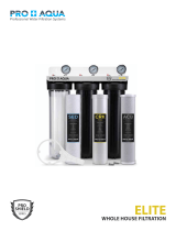
Pictured:
CS-BB-FUGAC200A-1 with Spanner Wrench and filter
cartridges, BB-PRESED-50-SW and BB-GACB-10-RFA
REPLACEMENT FILTERS
Part No. Description Replacement Time**
BB-PRESED-50-SW 50 Micron String Wound Sediment Cartridge Up to a Year
BB-GACB-10-RFA 20” Carbon Block Radial Flow Cartridge Up to a Year
SET-UP, INSTALLATION OF UNIT & BYPASS AND START-UP:
Unpack the unit. Unit comes completely assembled with the following:
Pre-Sediment and Post Carbon lters, housings with mounting bracket and spanner wrench
Identify an appropriate mounting location adjacent to the water line intended for installation.
Unit can be mounted in indoor or outdoor locations.
WARNING: Never allow unit to freeze. Avoid temperatures above 120
O
F.
If outdoors, unit must be protected from direct sun and heat.
Turn off the water supply. Route the cold water supply into the inlet side (clearly marked IN/FEED/STAGE 1) of the unit. Install
using proper plumber supplied pipe, ttings, unions and ball (shut-off) valves to the inlet, outlet and required bypass of the
unit for proper maintenance and lter service.
NOTE: GROUND CONTINUITY: Installed bypass with copper piping maintains electric continuity for the proper ground of
plumbing system. If bypass is not installed, a jumper is needed (copper wire clamped) between any metal piping
before and after the unit to maintain the proper ground.
WARNING: Use of teon tape is the only sealant to be used on threaded connections. NO pipe dope.
Do not cross-thread or over-tighten
Once unit installation and bypass is complete, slowly open (less than 1/2 regular ow rate or less than 5 gpm) inlet of unit
and close bypass. Keep outlet of unit closed and allow unit to ll slowly. Check unit at inlet connections, housings, bracket
and housing connections.
Once lled, open inlet and outlet of unit completely. Check all connections.
Flush unit of carbon nes. Find nearest faucet to the unit, remove aerator or any restriction, and open cold side only. Allow
carbon nes to ush through faucet until water runs clear. Open all faucets to clear air in lines.
Afx a plumber service label or card on unit and record installation date. Leave this booklet and warranty booklet with unit
and/or consumer. Replace lters up to one year after initial installation and/or at regular or needed intervals.**
WARNING: It is recommended that working pressure does not exceed or surge above 75 PSI and that a working PRV
be installed to control high household pressure and/or pressures surges.
Picture for Illustration Purposes Only:
Model may have white or black brackets
1.
2.
3.
4.
5.
6.
7.
**Up to one year or as needed, based on local water conditions, usage and ow rates. Diminished ow rate or ltration issues indicates cartridge change
needed. Application for known municipally treated or well water of known quality. All waranties and application requirements apply. For other performance
requirements or applications, other models are available.
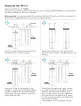
Turn off water supply to lter. Keep bypass closed. Open water in home at nearest faucet to relieve pressure
Unscrew blue housings using spanner wrench.
CAUTION: Do not lose O-Ring that are in blue housings. When opening housing to change cartridge, it is common
for the O-Ring to lift out of blue housing or stick to black cap.
Remove used cartridges and discard.
RECOMMENDED: Rinse out housings and ll about 1/3 full with water. Add about 2 to 3 tablespoons of bleach and scrub thoroughly
with a brush or sponge. Rinse thoroughly.
Remove O-Ring from blue housings and wipe groove and O-Ring clean. Lubricate O-Ring with a coating of
clean silicone grease. (Do not use Vaseline or other petroleum-based lubricants.) Place O-Ring back in
place and press O-Ring down into the groove with two ngers.
NOTE: This step is important to ensure proper seal. Make sure the O-Ring is seated
level in the groove.
CAUTION: If O-Ring appears damaged or crimped it should be replaced at this time.
See your local dealer for replacement parts.
Insert the new replacement lter cartridges in the proper order (Pre-Sediment in Stage 1
and Green Carbon lter in Stage 2)
into the blue housings making sure that lters slide
down over the housing stand-pipe found at the bottom of the housing.
CAUTION: The standpipe must insert properly into the bottom of the lter before
you go to Step # 7
Twist the blue housings onto the black caps and hand tighten.
WARNING: Do not overtighten or cross thread
CAUTION: Make sure the top standpipe found at the base of the black cap seats
properly into the top of each lter.
Turn on the water supply slowly to allow housings to ll with water. Allow water to
ow through the open faucet. Close faucet when water runs clear
REPLACING THE FILTERS
1.
2.
3.
4.
5.
6.


