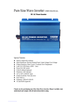
iTechworld 2000W User guide

Type
User guide

iTechworld 2000W pure sine wave inverter provides reliable power for sensitive electronics, appliances, and tools. Featuring a compact design, it's ideal for RVs, boats, camping, or emergency backup power. With a 5V USB port for charging devices, multiple AC outlets, and a remote control option, it offers versatility and convenience. Its pure sine wave output ensures compatibility with sensitive electronics, preventing damage and ensuring optimal performance. The iTechworld 2000W inverter is a dependable power solution for various applications.

iTechworld 2000W pure sine wave inverter provides reliable power for sensitive electronics, appliances, and tools. Featuring a compact design, it's ideal for RVs, boats, camping, or emergency backup power. With a 5V USB port for charging devices, multiple AC outlets, and a remote control option, it offers versatility and convenience. Its pure sine wave output ensures compatibility with sensitive electronics, preventing damage and ensuring optimal performance. The iTechworld 2000W inverter is a dependable power solution for various applications.

Pure Sine Wave Inverters
12 Volt Inverters
(2000W/3000W Models)
(Revised 01/2022)
USER GUIDE
WARNINGS AND SAFETY
For safe operation and ideal performance, the iTechworld inverter must
be correctly installed and operated correctly. Please carefully read,
understand and follow all instructions and guidelines in this User Guide.
iTechworld recommends that all wiring and installation be done by a
certified technician or licensed electrician to ensure all applicable
electrical wiring regulations and installation codes are met. Failure to
follow these instructions may result in damage to the unit and could
also result in may result in death or serious injury.
Disclaimer:
While iTechworld has taken every precaution to ensure the accuracy of
the contents of this user guide, iTechworld assumes no responsibility for
any errors or omissions.
Furthermore, all specifications and functionality may change at any time
without notice.
Important:
Please read and understand the entirety of this user guide before using
your iTechworld inverter. Any misuse may result in damage to the unit
and/or cause harm or serious injury to the user.
!!FAILURE TO FOLLOW THESE INSTRUCTIONS MAY RESULT IN
DEATH OR SERIOUS INJURY!!
1. DANGER ELECTRICAL SHOCK HAZARD: Do not disassemble the
inverter. The inverter contains hazardous voltages inside.
Attempting to service any internal components will void
warranty and may result in death or serious injury.
2. DANGER ELECTRICAL SHOCK HAZARD: Do not expose the
inverter to bilge water, rain, snow, spray or dust. The inverter is
only intended for indoor use only.
3. DANGER ELECTRICAL SHOCK HAZARD: Operating the inverter
without proper grounding may result in death or serious injury.
Please ensure that proper ground connections are made during
installation. Please consult a licensed electrician if you are
unsure.
4. DANGER ELECTRICAL SHOCK HAZARD: Before attempting to
clean the inverter disconnect DC power and any circuits
connected to the inverter.
5. DANGER ELECTRICAL SHOCK HAZARD Keep away from children:
The inverter produces 240VAC, treat the AC output receptacles
the same as regular wall AC sockets at home.
6. DANGER: Do not under any circumstances connect the output
terminals of the inverter to an incoming AC source, this will
result in permanent damage to the inverter and void all
warranties.
7. DANGER EXPLOSION HAZARD: Do not use the inverter in an
environment where flammable fumes or gases are present
(such as gas bottles, petrol engines or lead acid battery
compartments)
8. Warning: Do not use substandard or damaged wiring with this
inverter, it may cause fire or a shock hazard.
9. Warning: When connecting the DC input, pay close attention to
the polarity of the input. As a reverse polarity connection will
cause permanent damage to the inverter and void all warranty.
10. Warning: When using inductive loads, please note that they can
draw up to 10 times its rated power draw. Furthermore, when
running appliances with a locked rotor current such as pumps,
or compressors, please turn of other non-essential appliances
that are connected to the inverter.
11. Warning: Please ensure all ventilation vents and fan vents are
not obstructed in any way. Please keep a minimum of 60mm
distance around the sides of the inverter to ensure adequate
ventilation. Failure to do so may result in fire or failure of the
inverter.
12. Warning: Avoid dropping any metal tools or objects on the
battery. Doing so could create a large spark or short circuit
which may cause an explosion.
13. Warning: Batteries can supply very large currents in the event
of a short circuit. A fuse must be installed on the positive supply
cable as close as practical to the battery. Failure to do so
provides inadequate protection in the event of a short circuit
and may result in a fire hazard.
14. LIMITATIONS OF USE:
Do not use in connection with life support systems or other
medical equipment or devices.
USER GUIDE
Introduction:
Thank you for purchasing the iTechworld pure sine wave inverter. These
inverters produce a pure sine wave output, matching the output of your
home 240V AC power point, allowing you to power sensitive electronic
appliances, such as laptops and many AC powered devices anywhere.
The iTechworld pure sine wave inverter also provides 5V USB power,
allowing you to power or charge many devices that require 5V USB
power.
Key Features:
- Remote operation available (Optional Accessory)
- 1 x USB port: 5V 2.1A
- Temperature and load controlled cooling fans for quiet and
optimal performance
- Pure sine wave output
- LED status indicators with audible alarm
- Australian standard 240V receptacle with hard wire terminal
connections (only on 3000W model, requires licensed electrician
for installation)
- Heavy duty aluminium case for durability and cooling.
Specifications
Model
2000
3000
Input
Voltage
12VDC
Max Rated
Current
238A
375A
Fuse Size
250A
450A
High Voltage
Protection
16VDC ± 0.5VDC
Low Voltage
Protection
10.5VDC ± 0.5VDC
Efficiency
More than 85%
Output
Rated Output
Power
2000W
3000W
Surge Power
(10 sec)
2400W ~
3000W
3600W~4500W
Surge Power
(2 sec)
3000W ~
4000W
4500W ~ 6000W
AC Voltage
240VAC
AC Output Regulation: 10%
AC short circuit & Overload
Protection
Waveform
Pure Sine Wave (<3% THD) at rated
input voltage
Frequency
50Hz±1%
Environment
Operating
Temperature
-15°C to 40°C
Storage
Temperature
-40°C to 85°C
Relative
Humidity
20% ~ 90% RH non-condensing
Weight
5.3kg
7.6kg
Dimensions
(LxWxH)
360×220×83mm
360×220×150mm
Front Panel
Figure 1- 2000W inverter front panel
A
AC Output Receptacle
B
Main Switch
C
Power LED Indicator
D
Fault LED Indicator
E
5V USB Socket
F
Remote Control Port (RJ11) For connecting the optional remote-
control switch panel.
G
Chassis Ground Terminal
Front Panel Continued
Figure 2- 3000W inverter front panel
A
AC Output Receptacle
B
Main Switch
C
Power LED Indicator
D
Fault LED Indicator
E
5V USB Socket
F
Remote Control Port (RJ11) For connecting the optional remote-
control switch panel.
G
Chassis Ground Terminal
H
Hard-wire terminal block for use if loads are 15A or more
(MUST BE CONNECTED BY A LICENSED ELECTRICIAN)
Front Panel Continued
A. AC Output Receptacle
Figure 3- Standard 10A 240VAC Australia / New Zealand receptacle
For connecting 240VAC appliances to the inverter
B. Main Switch
The main switch is used for turning ON or OFF the output of the
inverter.
With the switch in the ON position, the Power indicator LED(C) will
glow green, and a single beep will be emitted to indicate 240VAC is
being produced.
C. Power LED indicator
Illuminates green to show that the inverter is outputting 240VAC
power.
D. Fault LED indicator
Will illuminate/flash red when a fault is detected, the 240VAC output
will be turned off. Please refer to the troubleshooting section.
E. 5V USB Socket
USB socket is for charging/powering 5V USB devices, such as mobile
phones. When the inverter is connected to a battery, the 5V USB port
will continuously output power, regardless of whether the Main
Switch(A) is in the ON or OFF position.
F. Remote Control Port (RJ11)
The remote-control port is for connecting the optional remote-control
panel (sold separately).
Front Panel Continued
G. Chassis Ground Terminal
A proper ground connection must be made before using the inverter.
The inverter is grounded through the grounding terminal located on
the front panel near the 240V outputs.
The chassis ground terminal must be connected to the negative
terminal of the DC input. Please use minimum 1.5mm² cable. Please
consult with a Licensed Electrician to ensure your application meets
current Australian/New Zealand standards.
H. 3000W inverter hard-wire terminal block
Figure 4- 3000W inverter hard-wire terminal block
Connection designations:
L- Live/Active G- Ground/Earth
N- Neutral
When using loads requiring 15Amps or more, the hard-wire
terminal block must be used.
Make sure the terminal block cover is installed prior to
turning on the inverter.
DANGER ELECTRICAL SHOCK HAZARD: ONLY LICENSED
ELECTRICIANS ARE PERMITTED TO CONNECT LOADS TO THE HARD-
WIRE TERMINAL BLOCK
Rear Panel
Figure 5- 2000W inverter rear panel
Figure 6- 3000W inverter panel
A
B
A. Cooling fan
The cooling fan(s) on the inverter are temperature and/or load
controlled.
The fan(s) will automatically turn on when the AC load is 20% or
more, or when the internal temperature is above 45°C.
Rear Panel Continued
B. DC Input Terminals
Warning: When connecting the DC input, pay close attention to the
polarity of the input. As a reverse polarity connection will cause
permanent damage to the inverter and void all warranty.
Warning: A fuse or DC circuit breaker is required; it must be installed
no further than 20cm from the positive terminal of your battery.
Failure to install a fuse or circuit breaker could cause a fire.
Please use the recommended fuse and minimum cable size as shown
in the table below. Please keep the DC input cables as short as
possible, if longer run cables are required, please use a larger cable.
Recommended Cable Size and Fuse Rating.
Model
Cable Size
Fuse/ Circuit Breaker
2000W
Inverter
25mm² for
lengths <1M
250A
3000W
Inverter
35mm² for
lengths <1M
450A
Remote Control
(Sold Separately)
Figure 7 - Optional Remote Control
A
Remote Control Main Switch
B
Fault LED Indicator
C
AC Output Indicator
D
Inverter Load Indicator
E
DC Input Power Indicator
F
Battery Capacity Indicator
A. Remote Control Main Switch
The main switch is used for turning ON or OFF the output of the
inverter. With the switch in the ON position, the AC Output
Indicator LED(C) will glow green to indicate 240VAC is being
produced.
B. Fault LED Indicator
Will illuminate/flash red when a fault is detected, the 240VAC
output will be turned off. Please refer to the troubleshooting
section.
C. AC Output Indicator
Will illuminate green to show that the inverter is outputting
240VAC power.
D. Inverter Load Indicator
Displays the approximate load being drawn from the inverter.
E. DC Power Indicator
Will illuminate green to show that DC power is being supplied to
the inverter.
F. Battery Capacity Indicator
Displays the approximate remaining capacity of the battery
running that is connected to the inverter.
Connecting the remote control
The remote control is connected to the inverter with the communications
cable, the communications cable supplied with the purchase of the
remote control. The cable is a 6-conductor RJ11 cable (the pinout of the
connector is a Straight Pinout and NOT Reverse, refer to the image
below). The cable is connected to the RJ-11 ports found on the rear of the
remote and on the front panel of the inverter (Port F in figures 1 and 2).
Using the remote control
When using the remote control to turn the inverter on or off, please make
sure the Main Switch on the inverter front panel is in the OFF position, or
the remote-control main switch will not work.
INSTALLATION
Mounting the inverter
The location where the inverter is to be mounted must be:
Dry: Do not allow any liquids to drip or splash onto the unit.
Cool: Do not install in direct sunlight or close to any heat sources,
the ideal ambient air temperature is between 15°C to 25°C.
Ventilated: Allow at least 60mm of clearance around the inverter
to allow adequate air flow, and make sure that the fans and vent
holes are not obstructed.
Safe: Do not install the inverter in the same compartment as the
batteries (only applies to Lead Acid, AGM, Gel and Sealed Lead
Acid) to prevent corrosion, or in any compartments where
flammable liquids or fumes may be or may become present.
Clean: Do not install the inverter in a dusty environment, as the
inverter contains cooling fans, any dust present will be sucked
into the inverter which may damage or shorten the life of the
inverter.
Close to batteries: Avoid excessive cable lengths as this will cause
voltage drop and lowers the performance of the inverter.
Fused: A fuse must be installed between the battery and the
inverter.
Note: This inverter may generate radio frequency energy, if not installed
and used in accordance with the instructions in this user guide, this
inverter may cause interference with radio communications. There is no
guarantee that interference will not occur in a particular installation. If
the inverter does cause interference to radios or television reception,
which can be determined by turning the inverter off and on, if this is the
case you may try to correct the interference by one or more of the
following possible solutions:
Reorient or relocate the receiving antenna of the affected
device
Increase separation between the affected device and the
inverter
Consult the dealer or an experienced radio/TV technician for
help.
INSTALLATION CONTINUED
DANGER ELECTRICAL SHOCK HAZARD: iTechworld recommends that all
wiring and installation be done by a certified technician or licensed
electrician to ensure all applicable electrical wiring regulations and
installations codes are met. Failure to follow these instructions may
result in damage to the unit and could also result in may result in death
or serious injury.
Warning: When connecting the DC input, pay close attention to the
polarity of the input. As a reverse polarity connection may cause
permanent damage to the inverter and void all warranty.
Figure 8 recommended wiring diagram.
Connecting the inverter
Before connecting the DC input connections to the inverter, make sure
that the main and remote main switch (if remote is installed) (refer to
Figures 1, 2 and 7) are in the OFF position.
1. Connect one end of the positive DC input cable to the inverter’s
positive DC input terminal.
Connect the other end of the positive DC input cable to one of
the terminals of the fuse holder or circuit breaker. Then connect
another DC input cable from the other terminal of the fuse
holder/ circuit breaker to the positive terminal of your battery.
2. Connect one end of the negative DC input cable to the inverter’s
negative DC input terminal.
Connect the other end of the negative DC input cable to the
negative battery terminal.
Caution: When connecting the negative cable to the negative
terminal of the battery, some sparking may occur, this is due to
the internal capacitors charging up and is normal. It is best to
spread the load across 2 batteries connected in parallel (i.e., Have
the positive connection to the inverter on one battery, and the
negative battery connection to the last battery in the battery
array)
Caution: Please ensure that all DC connections are tight, as any loose
connections could result in overheating and could be a potential fire
hazard.
Operating the inverter
1. Before turning on the inverter, make sure the connected AC
appliance is turned OFF.
2. Turn on the inverter by moving the Main Switch to the ON
position.
3. Once the Power LED indicator is illuminated, turn on the
connected AC appliance.
4. Once you are done with using the connected AC appliance, turn
off the appliance, then turn off the inverter by moving the Main
Switch to the OFF position.
Please note, although the inverter can provide high surge power up to
double the rated power output, some appliances may still trigger the
inverter overload protection. If this is the case, a larger inverter will be
required for those appliances.
  • Page 1 1
  • Page 2 2
  • Page 3 3
  • Page 4 4
  • Page 5 5
  • Page 6 6
  • Page 7 7
  • Page 8 8
  • Page 9 9
  • Page 10 10
  • Page 11 11
  • Page 12 12
  • Page 13 13
  • Page 14 14
  • Page 15 15
  • Page 16 16
  • Page 17 17
  • Page 18 18
  • Page 19 19
  • Page 20 20
  • Page 21 21
  • Page 22 22
  • Page 23 23
  • Page 24 24
  • Page 25 25
  • Page 26 26
  • Page 27 27
  • Page 28 28

iTechworld 2000W User guide

Type
User guide

iTechworld 2000W pure sine wave inverter provides reliable power for sensitive electronics, appliances, and tools. Featuring a compact design, it's ideal for RVs, boats, camping, or emergency backup power. With a 5V USB port for charging devices, multiple AC outlets, and a remote control option, it offers versatility and convenience. Its pure sine wave output ensures compatibility with sensitive electronics, preventing damage and ensuring optimal performance. The iTechworld 2000W inverter is a dependable power solution for various applications.

Ask a question and I''ll find the answer in the document

Finding information in a document is now easier with AI