Avantco 177FF300N User manual

Category
Deep fryers
Type
User manual

Avantco 177FF300N is a floor fryer designed for commercial use. It is equipped with three 30,000 BTU burners, allowing for a total of 90,000 BTUs per hour. This model has a 40-pound capacity fry pot with a 1/2-inch pipe connection for easy installation. Additional features include adjustable leveling legs for stability and a built-in thermostat for precise temperature control. Safety features like flame failure protection ensure safe operation, and the unit is suitable for use on combustible floors.

Avantco 177FF300N is a floor fryer designed for commercial use. It is equipped with three 30,000 BTU burners, allowing for a total of 90,000 BTUs per hour. This model has a 40-pound capacity fry pot with a 1/2-inch pipe connection for easy installation. Additional features include adjustable leveling legs for stability and a built-in thermostat for precise temperature control. Safety features like flame failure protection ensure safe operation, and the unit is suitable for use on combustible floors.

User Manual
1
Floor Fryers
Models: 177FF300N, 177FF300L, 177FF400N, 177FF400L, 177FF518N,
177FF518L
Please read and keep these instructions. Indoor use only.
02/2022
User Manual
User Manual
2
WARNING
Fire Hazard - For your Safety
Do not store or use gasoline or other flammable vapors and liquids in the vicinity of this or any
other appliance.
Keep area around appliances free and clear of combustibles.
Purchaser of equipment must post in a prominent location, detailed instructions to be followed
in the event the operator smells gas. Obtain the instructions from the local gas supplier.
NOTICE
Avantco Floor Fryers are intended for commercial use only. Not for household use.
Warranty will be void if service work is performed by anyone other than a qualified technician, or
if other than genuine Avantco replacement parts are installed.
Be sure this Operators Manual and important papers are given to the proper authority to retain
for future reference.
Safety Precautions
Before installing and operating this equipment, be sure everyone involved in its operation is fully
trained and aware of precautions. Accidents and problems can be caused by failure to follow
fundamental rules and precautions.
The following symbols, found throughout this manual, alert you to potentially dangerous conditions
to the operator, service personnel, or to the equipment.
DANGER!
WARNING!
CAUTION!
NOTICE!
This symbol warns of immediate hazards that will result in severe injury or death.
This symbol refers to a potential hazard or unsafe practice that could result in injury or death.
This symbol refers to a potential hazard or unsafe practice that could result in injury, product
damage or property damage.
This symbol refers to information that needs special attention or must be fully understood,
even though not dangerous.
!
!
!
!
!
!
!
!
WARNING
WARNING
Burn Hazard
Contact with hot oil will cause severe burns. Always use caution. Oil at 20F is more dangerous
than boiling water.
In the event a gas odor is detected, shut down equipment at the combination gas valve and
contact the local gas company or gas supplier for service.
User Manual
3
RETAIN THIS MANUAL FOR FUTURE REFERENCE.
Models
This manual is for Avantco Fryers with 40-pound (FF300), 50-pound (FF400), and 70-100-pound
(FF518) capacity fry pots. The capacity is described on the serial plate that is located inside the
front door on the left side.
Table of Contents
Specifications . . . . . . . . . . . . . . . . . . . . . . . . . . . . . . . . . . . . . . . . . . . . . . . . . . . . . . . . . . . . . 4
Installation . . . . . . . . . . . . . . . . . . . . . . . . . . . . . . . . . . . . . . . . . . . . . . . . . . . 5
Operation . . . . . . . . . . . . . . . . . . . . . . . . . . . . . . . . . . . . . . . . . . . . . . . . . . . . . . . . . 10
Cooking Hints . . . . . . . . . . . . . . . . . . . . . . . . . . . . . . . . . . . . . . . . . . . . . . . . . . . . . . 12
Cleaning . . . . . . . . . . . . . . . . . . . . . . . . . . . . . . . . . . . . . . . . . . . . . . . . . . . . . . . . . . 12
Trouble Shooting . . . . . . . . . . . . . . . . . . . . . . . . . . . . . . . . . . . . . . . . . . . . . . . . . . . . . . . . . . . .14
Parts . . . . . . . . . . . . . . . . . . . . . . . . . . . . . . . . . . . . . . . . . . . . . . . . . . . . . . . . . . . . . . 18
Read these instructions carefully before attempting installation. Installation and initial startup should
be performed by a qualified installer. Unless the installation instructions for this product are followed
by a qualified service technician (a person experienced in and knowledgeable with the installation
of commercial gas and/or electric cooking equipment) then the terms and conditions on the
Manufacturer’s Limited Warranty will be rendered void and no warranty of any kind shall apply.
User Manual
4
Specifications
Gas Suppy and Burner Information
Supply pressure should be minimum of 4" W.C. for natural gas or 10" W.C. for propane. The fryer comes with 3/4"
NPT male connector on a 1/2" pipe, allowing you to connect with either 3/4" or 1/2" NPT female connector.
Model Burners Gas Type Manifold
Pressure
Number of
Heat Tube
Rate Each
BTUs / Hour
Total Rate
BTUs / Hour
Orifice
Size
177FF300 Main Natural 4" W.C. 3 30,000 90,000 #39
Propane 10" W.C. 3 30,000 90,000 #52
177FF400 Main Natural 4" W.C. 4 30,000 120,000 #39
Propane 10" W.C. 4 30,000 120,000 #52
177FF518 Main Natural 4" W.C. 5 30,000 150,000 #39
Propane 10" W.C. 5 30,000 150,000 #52
* Minimum supply pressure is 4" W.C. for natural gas and 10" W.C. for propane.
** Orifice sizes are for units installed at altitudes between 0 and 2000 feet above sea level.
User Manual
5
Installation
Please read this manual thoroughly prior to equipment set-up, operation and maintenance.
NOTICE
Installation must conform with local codes, or in the absence of local codes, with the
National Fuel Gas Code, ANSI Z223.1, Natural Gas Code, CAN/CGA-B149.1, or the
Propane Installation Code, CAN/CGA-B149.2, as applicable.
These installation procedures must be followed by qualified personnel or warranty will be
void. Local codes regarding installation vary greatly from one area to another. The National
Fire Protection Association, Inc. states in its NFPA 96 latest edition that local codes are the
“authority having jurisdiction” when it comes to installation requirements for equipment.
NOTICE
!
!
User Manual
6
Step 1: Install the Legs (or optional casters)
and Restraints.
1. Raise fryer sufficiently to allow legs or casters to be screwed into the baseplate. For safety, “shore up”
and support the fryer with an adequate blocking arrangement strong enough to support the load.
2. Screw the four legs or casters to the plate on the bottom of the fryer. When casters have been ordered,
the casters having a locking-brake should be attached under the front of the fryer.
3. Lower the fryer gently. Never drop or allow the fryer to fall.
4. Use a level to make sure that the fryer is level. Each caster, or the tubular-end of each leg, can be
screwed in or out to lower or raise each corner of the fryer.
5. Attach restraints as required by local codes.
NOTICE
Unit must be level to ensure maximum performance. Improper leveling may void warranty.
When this appliance is installed with casters, it must be installed with the casters supplied, a connector
complying with either ANSI Z21.69 or CAN/CGA-6.16 and a quick disconnect device complying with
either ANSI Z21.41 or CAN1-6.9. It must also be installed with restraining means to guard against
transmission of strain to the connector, as specified in the appliance manufacturer's instructions.
When this appliance is installed with casters, it must be installed with the casters supplied, a connector
complying with either ANSI Z21.69 CSA 6.16 and a quick-disconnect device complying with ANSI
Z21.41 CSA 6.9. It must also be installed with restraining means to guard against transmission of strain
to the connector, as specified in the appliance manufacturer instructions.
WARNING
All fryers must be restrained to prevent tipping in order to avoid the splashing of hot liquid. The means
of restraint may be the manner of installation.
WARNING
If disconnection of the restraint is necessary to move the appliance for cleaning, etc., reconnect it when
the appliance is moved to its original installed position.
A set of legs or casters is packed with the fryer. Mounting fasteners are pre-mounted
on the baseplates.
!
!
!
!
!
WARNING
NOTICE
User Manual
7
NOTICE
Unit must be level to ensure maximum performance. Improper leveling may void warranty.
Step 2: Flue Installation
1. Unpack the flue box and flue wrap.
2. Slide the flue box over the flue and secure it with the two self-tapping screws using a 5/16" socket.
3. Slide the flue wrap over the flue. 4. Secure it with four self-tapping screws two on the back and
one on each side using a 5/16" socket.
User Manual
8
.
Step 3: Check Clearances and Ventilation
Select a firm, level location for your fryer. Leave clearance, whenever possible, so that access from
the rear is possible to permit cleaning. If the unit is to be set on non-combustible flooring, such as a
concrete slab, 3 inches minimum toe room must be provided to prevent restriction of the air opening
in the bottom of the unit.
There must be adequate clearance between fryer(s) and construction. Clearance must also be provided in front for
servicing and for operation.
Minimum Clearances From Combustible Construction:
Sides: 6"
Rear: 6"
ALL AVANTCO FLOOR FRYERS SHALL BE INSTALLED WITH AT LEAST A 16 INCH SPACE BETWEEN THE FRYER AND
SURFACE FLAMES FROM ADJACENT EQUIPMENT.
SUITABLE FOR INSTALLATION ON COMBUSTIBLE FLOORS. No additional side and rear clearance is required for
service as the fryer is serviceable from the front.
Improper ventilation can result in personal injury or death. Ventilation that fails to
properly remove flue products can cause headaches, drowsiness, nausea, or could
result in death.
Unit Must be installed under a ventilation Hood.
All units must be installed in such a manner that the flow of combustion and ventilation
air is not obstructed. Provisions for adequate air supply must also be provided. Do NOT
obstruct the bottom front of the unit, as combustion air enters through this area. Be
sure to inspect and clean the ventilation system according to the ventilation equipment
manufacturer’s instructions.
Due to the variety of problems that can be caused by outside weather conditions, venting by hoods or wall fans is
preferred over any type of direct venting. It is recommended that a hood extend 6" past the appliance and the bottom
edge be located 6'6" from the floor. Filters should be installed at an angle of 45° or more from the horizontal. This
position prevents dripping of grease and facilitates collecting the run-off grease in a drip pan, usually installed with a
filter. A strong exhaust fan tends to create a vacuum in the room and may interfere with burner performance or may
extinguish pilot flames. Fresh air openings approximately equal to the fan area will relieve such a vacuum. In case of
unsatisfactory performance on any appliance, check the appliance with the exhaust fan in the “OFF” position. Do this
only long enough to check equipment performance, then turn hood back on and let it run to remove any exhaust that
may have accumulated during the test.
The exhaust fan should be installed at least 2 feet above the vent opening at the top of the fryer.
Make sure all ventilation meets local code requirements.
This unit is not intended to be connected directly to an outside flue.
Ventilation Notes
!
!
WARNING
WARNING
User Manual
9
Step 4: Gas Connection
This Fryer ships from the factory configured for areas with an altitude that is lower than 2,000 feet. (If being
installed above 2,000 feet the orifices will need changed. Failure to install proper orifice size will void warranty)
3/4" Male NPT line for gas connection is located near the lower right rear corner of the fryer.
Recommended Regency 48" Gas lines: (more sizes available)
Mobile: 600GKM3448
Stationary: 600GKS3448
1. Ensure gas supply and gas type, as shown on unit serial plate agree. Unit installation must conform with the
National Fuel Gas Code, ANSI Z223.1, the National Gas Installation Code, CAN/CGA-B149.1, or the Propane
Installation Code, CAN/CGA-B149.2 as applicable and in accordance with local codes.
2. A manual gas shut-off valve must be installed in the gas supply line ahead of the appliance and gas pressure
regulator for safety and ease in servicing.
3. The gas pressure regulator supplied must be installed on the appliance prior to connecting the equipment to the
gas line. Failure to install a regulator could be potentially hazardous and will void limited equipment warranty.
4. Pipe threading compound must be resistant to the action of liquefied petroleum gases.
5. Connect the gas supply directly to the 3/4" male NPT connector located near the lower left rear corner of the
fryer. When tightening the supply pipe, be sure to hold the mating connector extending from the unit securely with
a wrench.
ALL PIPE JOINTS AND CONNECTIONS MUST BE TESTED THOROUGHLY FOR GAS LEAKS. USE
ONLY SOAPY WATER FOR TESTING ON ALL GASES. NEVER USE AN OPEN FLAME TO CHECK
FOR GAS LEAKS. ALL CONNECTIONS MUST BE CHECKED FOR LEAKS AFTER THE UNIT HAS
BEEN PUT INTO OPERATION. TEST PRESSURE SHOULD NOT EXCEED 14" W.C.
THIS APPLIANCE AND ITS INDIVIDUAL COMBINATION GAS VALVE MUST BE DISCONNECTED
FROM THE GAS SUPPLY PIPING SYSTEM DURING ANY PRESSURE TESTING OF THAT SYSTEM
AT TEST PRESSURES IN EXCESS OF 14”WC (1/2 PSIG or 3.45 kPa).
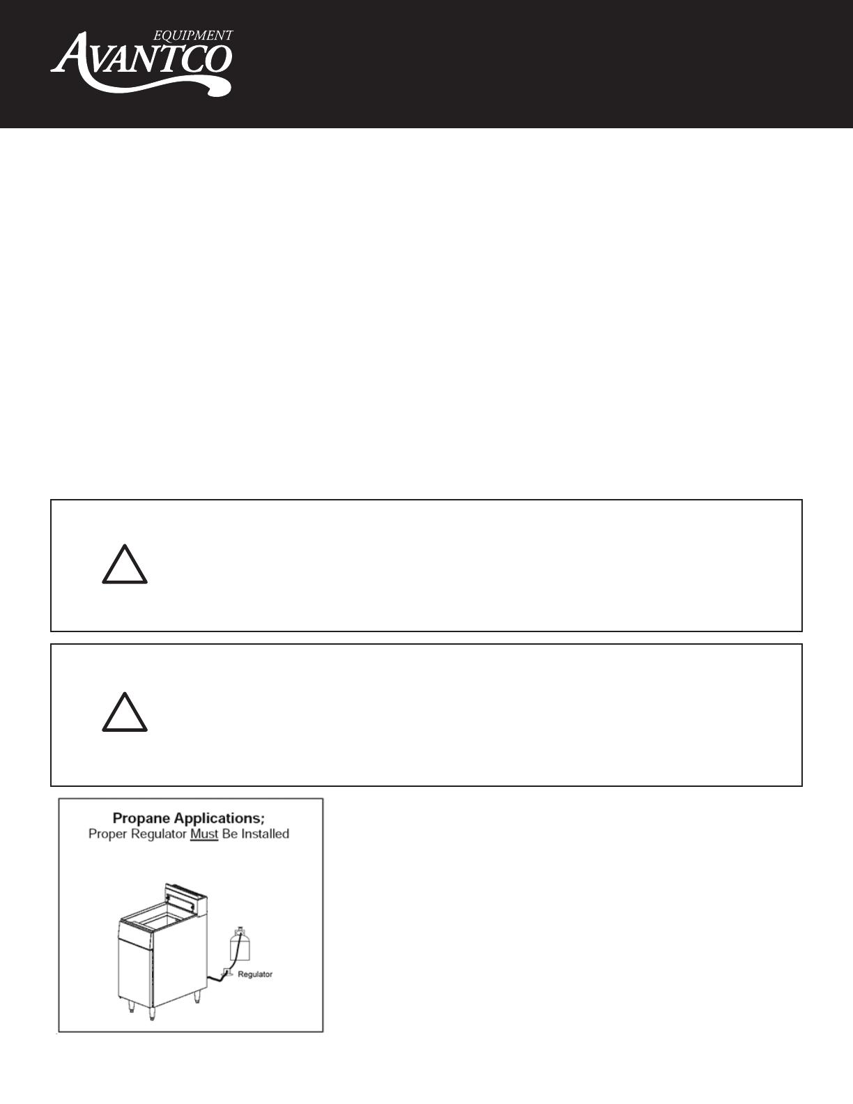
If the incoming gas pressure is in excess of 14"WC (1/2PSI, 3.45 kPa), a proper
step-down regulator will be required. See PHOTO 1 for LP application
CAUTION
CAUTION
!
!
Pressure Regulator:
A combination gas valve and pressure regulator, which is provided
with each unit, is set to maintain a 4" W.C. manifold pressure for natu-
ral gas or 10.0" W.C. manifold pressure for propane gas. However, to
maintain these conditions the pressure on the supply line, when all
units are operating simultaneously, should not drop below 7" W.C. for
natural gas or 11" W.C. for propane gas. Fluctuations of more than 25%
on natural gas or 10% on propane gas will create problems and affect
burner operating characteristics. A 1/8" tap to measure the manifold
pressure is located on the combination gas valve, which is on the
burner manifold located directly below the burners inside the cabinet.
User Manual
10
Open the burner compartment door and do the following:
1. Turn thermostat to “OFF” by aligning the "OFF" with the red indicator.
2. Press down the knob of the combination gas valve, turn it
counterclockwise to the "PILOT" position (shown), and continue to
press the knob down.
3. While pressing the knob down, use a lit match to ignite the pilot.
Continue to press the knob down for about 30 seconds. If the pilot
does not stay lit when the knob is released, repeat the lighting
procedure and keep the knob down longer. Adjustment of pilot flame
may be necessary.
4. When the pilot stays lit, turn the knob counterclockwise to the “ON”
position. Do not press down on the knob in this step.
5. Do NOT turn the thermostat “ON” until the fry pot is filled with oil or
solid shortening.
6. Once the fry pot is filled with shortening, set the thermostat to the
desired temperature
Operation
Lighting
CAUTION
CAUTION
IF YOU SMELL GAS DURING THE LIGHTING PROCEDURE, IMMEDIATELY SHUT OFF THE GAS SUPPLY
UNTIL THE LEAK HAS BEEN CORRECTED.
NEVER ATTEMPT TO MELT A SOLID BLOCK OF SHORTENING ON THE TOP OF THE HEAT TUBES.
NEVER START THE BURNERS WHEN THE FRYPOT IS EMPTY.
Filling the Fry Pot
1. Close drain valve completely before filling the fry pot.
2. When the fryer is new, fill the fry pot with water and clean thoroughly (see “Weekly Cleaning” on page 13) in
order to remove protective coatings and any foreign matter.
3. The recommended solid shortening capacity for the fry pot (35 pounds or 55 pounds) is described on the
serial plate (which is located inside the front door).
4. Remove the basket support frame when filling the fry pot with solid shortening.
5. When solid shortening is used, be careful not to bend, break, or twist the thin capillary wires of the sensing
elements located in the fry pot.
6. Pack solid shortening into the zone below the tubes, all spaces between the tubes, and at least an inch above
the top of the tubes before lighting the fryer. If any air spaces are left around the heat tube surfaces when the
heat is turned on, the tube surfaces will become red hot, burn the solid shortening, weaken the fry pot, and
could result in fire.
7. To prevent burning or scorching the solid shortening, keep the thermostat set at the lowest temperature until
all the solid shortening between and above the tubes has been melted. Additional solid shortening can then
be added until the desired frying depth has been reached.
8. Replace the basket support frame over the fry pot heat tubes.
!
!
Red Indicator
User Manual
11
Shutdown Procedure
Standby: Turn knob on the combination gas valve to the “PILOT” position. At this setting, only the pilot burner will
remain ignited.
Complete Shutdown: Turn knob on the combination gas valve clockwise, press down on the knob and continue to
turn to the “OFF” position.
Relighting
1. Shut off all gas.
2. Wait five minutes.
3. Follow the "Lighting" procedure as described on page 12.
In the event of a main burner ignition failure, a five minute purge period must be observed prior to
re-establishing the ignition source.
Automatic Pilot Valve
The Automatic Pilot Valve provides an automatic safety shutoff for the fryer when the pilot flame is extinguished.
When the pilot flame is burning, the valve is held open electromagnetically by the electrical current from a thermopile
in the pilot flame. When the pilot flame goes out, generation of current ceases and the valve closes automatically.
High Limit Control
Avantco Floor Fryers are equipped with a secondary heat control that prevents the oil temperature from rising above
450°F. (Because of the accuracy tolerance of the sensor, the oil temperature may reach as high as 475°F.)
In the event the fryer shuts down due to this condition, the oil must be cooled to below 400°F before the pilot burner
can be re-ignited. When the oil has cooled, use the “Lighting” procedure on page 12 to restore functionality.
If the problem persists, contact your Avantco Service Representative or the Avantco Service Department.
WARNING
!
User Manual
12
Cooking Hints
User Tips
Smoking oil means that the temperature is too high, or that the oil has broken down.
Gum in fry pot denotes a need for thorough cleaning (see “Weekly Cleaning” on page 15)
Use different oil for oily foods (mackerel, nutmeg, etc.) than for foods with water-soluble flavors (potatoes,
onions, etc.).
Taste oil for quality. Replace it regularly.
Poor oil cannot produce good food.
Cleaning
Avantco equipment is constructed with the best quality materials and is designed to provide durable service when
properly maintained. To expect the best performance, your equipment must be maintained in good condition and
cleaned daily. Naturally, the frequency and extent of cleaning depends on the amount and degree of usage.
Following daily and more extensive periodic maintenance procedures will increase the life of your equipment.
Climatic conditions (e.g., salt air) may result in the need for more thorough and more frequent cleaning in order to
keep equipment performing at optimal levels.
Tough on grease, Tough on carbon, and increases life of Oils.
Daily Cleaning
1. Turn thermostat knob to “OFF” position.
2. Place hot-oil safe container under the drain and drain the fry pot completely.
3. Remove the basket support frame (if applicable) and flush out any sediment remaining in the fry pot with a
little hot oil.
4. Wipe off the basket support frame and the inside of the fry pot with a clean cloth.
5. Close drain valve and strain the oil back into the fry pot through several thicknesses of cheesecloth, or filter it
back using a filter machine.
6. Replace the basket support frame (if applicable)
7. Add oil or shortening to MIN oil level mark on rear of fry pot.
8. To resume cooking, turn the combination gas valve knob to “ON” position.
WARNING: BURN HAZARD
If neccessary to move the fryer for cleaning, etc., drain oil first to avoid death or serious injury.
WARNING
If disconnection of the restraint is neccessary to move the appliance for cleaning, etc.,
reconnect it when the appliance is moved to its originally installed position.
CAUTION
SOME AREAS OF THE FRYPOT MAY BE HOT!
!
!
!
User Manual
13
Tough on grease, Tough on carbon, and increases life of Oils.
Weekly Cleaning
1. Follow steps 1 through 4 of the Daily Cleaning procedure (see previous section).
2. Close drain valve and fill fry pot with a solution of warm water and boil-out compound (999FCBOILOUT).
3. Relight the fryer and bring the solution to a gentle boil for at least five minutes.
4. Turn off main burners and let the solution stand until the gum deposits are softened and the carbon spots and
burned grease spots can be rubbed off.
5. Scrub the fry pot walls and heat tubes, then drain out fry pot and rinse it with clean water.
6. Refill the fry pot with clean water and boil again.
7. Turn off gas and drain and rinse well until clean.
8. Wipe dry with a clean cloth.
9. Refill as specified in the “Filling the Fry pot” section (see page 12).
Monthly Cleaning
1. Perform the Weekly Cleaning procedure (see previous section).
2. Clean around burner and orifices if lint has accumulated.
3. Visually check that burner carry-over ports are unobstructed.
Cleaning Stainless Steel Surfaces
Normal dirt:
Use ordinary soap and water (with or without detergent) applied with a sponge or cloth.
Dry thoroughly with a clean cloth.
Never use vinegar or any corrosive cleaner.
Grease and Food:
Apply cleanser to a damp cloth (recommended cleanser: 147FORMULAD) or sponge and rub cleanser on the metal
in the direction of the polishing lines on the metal.
Rubbing cleanser, as gently as possible, in the direction of the polished lines will not mark the finish of the stainless
steel.
Use scouring pads or stainless steel scouring pads for deposits still on the unit
Surfaces that are marred collect dirt more rapidly and become more difficult to clean. Marring also increases the
possibility of corrosive attack. Refinishing may then be required.
Darkened Areas: called “heat tint,” sometimes appear on stainless steel surfaces where the area has been subjected
to excessive heat. These are not harmful
Use the above techniques for removal
Tint that is not removed use scouring pads or a stainless steel scouring pad in combination with a powered cleanser.
rub in direction of the polish lines
WARNING
NEVER RUB WITH A CIRCULAR MOTION.
NEVER USE A WIRE BRUSH, STEEL SCOURING PADS (EXCEPT STAINLESS), SCRAPER, FILE OR
OTHER STEEL TOOLS
DO NOT USE ORDINARY STEEL WOOL, as any particles left on the surface will rust and further spoil
the appearance of the finish.
!
User Manual
14
Trouble Shooting
For Authorized Service Technicians Only!
CHECKING AND ADJUSTING MAIN BURNERS
The main burners should burn with a steady blue flame, and the inner cone of the flame from each port should be
about 3/4" long. The flame from each main burner should enter each heat tube without touching the front of the fry pot
or the sides, top, or bottom of each tube.
All units are adjusted at the factory. In case of problems in operation at initial installation, check type of gas and
manifold pressure and compare with information listed on the serial plate.
A mill voltage circuit diagram is located inside the front door of the fryer, and also on page 19.
Yellow Tips
(too little air or too much gas)
Blowing or Lifting Tips
(too much air)
Normal Flame
NOTICE
Warranty will be void and the manufacturer is relieved of all liability if:
(A) Service work is performed by other than a qualified technician (see page 30 for details)
OR (B) Other than approved Avantco replacement parts are installed.
WARNING
Adjustments and service work may be performed only by a qualified technician who is experience in,
and knowledgeable with, the operation of commercial gas cooking equipment. However, to ensure your
confidence,contact your Avantco Service Representative for liable service, dependable advice or other
assistance, and for genuine factory parts.
!
!
User Manual
15
CHECKING AND ADJUSTING PRESSURE REGULATOR
1. Turn thermostat “OFF” and combination gas valve knob to the “PILOT” setting.
2. Remove pressure tap plug from burner manifold located directly below the burners in the cabinet.
3. Install a fitting appropriate to connect a manometer.
4. Turn combination gas valve to “ON” position and thermostat to “ON.” The burners will ignite. Be
certain that sufficient oil is covering the tubes.
5. With burners on, read manometer.
6. If the manometer does not read 4" W.C. for natural gas, or 10" W.C. for propane gas, adjust regulator.
7. Remove regulator adjustment screw cap (see diagram on page 18).
8. With small screwdriver rotate adjustment screw “CLOCKWISE” to increase or “COUNTERCLOCKWISE”
to decrease pressure. Be sure to adjust with burners “ON.”
9. Turn thermostat “OFF” and set combination gas valve knob to “PILOT” position.
10. Remove manometer and replace pressure tap plug.
11. Replace adjustment screw cap.
CHECKING AND ADJUSTING CALIBRATION OF THERMOSTAT
1. To check appliance temperatures, use a thermocouple-type temperature test instrument or reliable
thermometer. Place the thermocouple of test instrument or thermometer in the center of the fry pot.
2. Turn the control dial to the temperature setting requiring the greatest accuracy. Allow enough time
for temperature to stabilize, or until several temperature readings are identical.
3. Recalibrate if setting and actual temperature
differ by more than 10°F.
4. Remove dial from dial shaft “B.” Be careful that
dial shaft does not rotate in either direction
(which would change the dial setting).
5. Hold dial shaft “B” steady and with a
screwdriver turn calibration screw “A
clockwise to decrease the temperature, or
counterclockwise to increase the temperature.
6. Replace dial. Let the appliance operate until
the temperature has stabilized before a final
check is made to determine whether or not the
calibration has been corrected.
7. Once correct, seal the calibration screw with
glyptol.
The combination gas valve (includes pressure regulator) is factory set at 4" W.C. for natural gas and 10" W.C.
for liquid propane gas. To check the manifold pressure, do the following:
All thermostat controls are carefully calibrated at the factory (i.e., the dial is properly set to control appliance
temperatures accurately). Only a qualified appliance service technician should perform this adjustment.
User Manual
16
2. Adjust pilot key to provide properly
sized ame as shown in diagram B.
Diagram A shows improperly adjusted
pilot.
3. Release pilot adjustment cap.
User Manual
www.AvantcoEquipment.com 15
E
NTREE
F
RYERS
SERVICE
ENTREE OPERATORS MANUAL #400024 PAGE 15

CHECKING AND ADJUSTING AUTO SAFETY PILOT
The pilot flame should surround the thermopile for 1/2". It must be large and sharp enough to cause the
thermopile to glow a dull red, or sufficient to hold the safety valve open.
1. Remove pilot adjustment cap
2. Adjust pilot key to provide properly
sized flame shown in diagram B.
Diagram A shows an improperly
adjusted pilot
3. Replace pilot adjustment cap.
TROUBLESHOOTING
 
 



 








 


 



NOTE: Vibrations or shock caused by shaking or pounding baskets on top surface or by slamming door may
cause Hi-Limit Control Switch to open. If this condition persists, additional cushioning may be added to the
rubber grommets supporting this control to absorb these shocks.
Checking and Adjusting Safety Pilot
1. Remove pilot adjustment cap.
The pilot flame should surround the thermopile for 1/2". It must be large and sharp enough to cause the thermopile to
glow a dull red, or sufficient to hold the safety valve open.
User Manual
17
Wiring Diagram
User Manual
18
Parts
NOTICE
INSTALLATION OF OTHER THAN GENUINE AVANTCO PARTS WILL VOID THE WARRANTY ON THIS EQUIPMENT
The serial plate is located inside the front door on the left side.
Replacement parts may be ordered either through a Avantco Authorized Parts Distributor or a Avantco Authorized
Service Agency.
When ordering parts, please supply the Model Number, Serial Number, Part Number, and Description.
User Manual
19
Gas Parts for Fryer (3 tube shown)
410
12
15
1
3
14
5
11
Key Part Number Qty Description
1 400045 1 Knob, thermostat
3 400044 1 Thermostat Fryer, regulating 200-400
4 400042 1 Combination Valve (Nat)
4 400146 1 Combination valve (LP)
5 400070 1 Tubing, º î fryer pilot
10 300031 ea Burner, Fryer
11 400043 1 Safety thermopile 18î
12 300034 ea Orifice # 39 (Nat) (as part of kit 266003)
12 300035 ea Orifice # 52 (LP) (as part of kit 266002)
14 400046 1 Thermostat, High limit 450F
15 400047 1 Pilot 3- way
Key Part Number Qty Description
1 177400045 1 Knob, Thermostat
2 177400044 1 Thermostat Fryer, regulating 200-400
3 177400042 1 Combination valve (Nat)
3 177400146 1 Combination valve (LP)
4 177400070 1 Tubing, 1/2" fryer pilot
5 177300038 1 Left burner, Fryer
5 177300037 1 Middle burner, Fryer
5 177300036 1 Right burner, Fryer
6 177400043 1 Safety thermopile 18"
7 177300034 1 Orifice #39 (Nat)
7 177300035 1 Orifice #52 (LP)
8 177400046 1 Thermostat, high limit 450F
9 177400048 1 Pilot 3-way (LP)
9 177400047 1 Pilot 3-way (Nat)
Gas Parts
1
2
3
4
5
6
7
8
9
User Manual
20
Key Part Number Qty Description
1 177400037 1 Screen for 177FF300/177FF400
1 177400056 1 Screen for 177FF518
2 177400036 1 Valve, Ball
3 177400071 1 Drain, Extension
Tank Parts
1
2
3
  • Page 1 1
  • Page 2 2
  • Page 3 3
  • Page 4 4
  • Page 5 5
  • Page 6 6
  • Page 7 7
  • Page 8 8
  • Page 9 9
  • Page 10 10
  • Page 11 11
  • Page 12 12
  • Page 13 13
  • Page 14 14
  • Page 15 15
  • Page 16 16
  • Page 17 17
  • Page 18 18
  • Page 19 19
  • Page 20 20
  • Page 21 21

Avantco 177FF300N User manual

Category
Deep fryers
Type
User manual

Avantco 177FF300N is a floor fryer designed for commercial use. It is equipped with three 30,000 BTU burners, allowing for a total of 90,000 BTUs per hour. This model has a 40-pound capacity fry pot with a 1/2-inch pipe connection for easy installation. Additional features include adjustable leveling legs for stability and a built-in thermostat for precise temperature control. Safety features like flame failure protection ensure safe operation, and the unit is suitable for use on combustible floors.

Ask a question and I''ll find the answer in the document

Finding information in a document is now easier with AI