Page is loading ...

Lossnay Signal Output Terminal
MODEL:
PZ-4GS-E
Installation and Instruction Manual
2107876H65501
1. Safety Precautions
WARNING Incorrect handling could cause serious injury or death.
- Use a dedicated circuit for the equipment to be connected, and use the voltage and breaker appropriate for the connected load.
- Connected equipment should be used within the rated voltage and control capacity range.
- Never modify or repair by yourself.
If the product is modied or inappropriately repaired, electric shock, re, etc. could result. Contact your dealer for repair.
- Do not move or reinstall the product by yourself.
If it is installed improperly, electric shock, re, etc. could result. Contact your dealer or technical representative.
-Usethespeciedcablesforwiringandconnectthemsecurely.Holdthecablessoasnottoapplyexternalforceofthecablestothe
Terminal block of this product.
Improper connection could result in heat generation or re.
- All electrical work must be performed by a licensed technician, according to local regulations and the instructions given in this Installation
manual.
- Ensure that installation work is done correctly following this Installation manual.
If it is installed improperly, electric shock, re, etc. could result.
- Close the control cover after installation.
-Donotinstalltheproductinaplacewhereammablegasesmayleak.
If gas should leak or accumulate around the product, re or explosion could result.
- Do not use the product in special environments.
The product could be damaged if it is used in locations subject to large quantities of oil (including machine oil), steam, or sulde gas.
-Donotinstalltheunitinaplacewherethetemperaturerisesabove40˚C(104°F),wherelargeamountsofoil,steam,organicsolvents,or
corrosive gases, such as sulfuric gas, are present, or where acidic/alkaline solutions or sprays are used frequently.
These substances can compromise the performance of the unit or cause certain components of the unit to corrode, which can result in electric
shock, malfunctions, smoke, or re.
CAUTION Incorrect handling could cause injury or damage to property or household eects.
- Wire so that it does not receive any tension.
Tension could cause wire breakage, heating or re.
- Put on gloves during installation.
Failure to do so could cause injury.
■ This manual must be read both fully and carefully before commencing installation procedures; furthermore, the subsequent installation must be
performed correctly and safely in accordance with the instructions given.
■ Be sure to give this instruction manual to the customer once installation is complete.
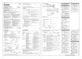
2. Dimensional Outline Drawing
60 (2 23/64)
53 (2 3/32)
86 (3 25/64)
Unit: mm (inch)
■AccessoryParts
Installation screws (cross recessed truss screws M4 x 8): 2
Connection cable (for connecting with the Lossnay unit): 1
Note:
Do not damage the circuit board during unpacking.

2
3. Installation Method
Be sure to perform installation while the power of the Lossnay
unit is OFF.
* Depending on the model of Lossnay or
installation condition, the actual PCB and
following diagram can be upside down.
3.1RemovingtheControlBoxCoverofthe
Lossnay Unit
For more information, please refer to the installation and
operation manual of the Lossnay.
* Figures show the installation method of LGH-RVS series.
Remove the three black screws and remove the control box cover
of the Lossnay unit.
3.2 Installing PZ-4GS-E
Use the included installation screws (2) to install PZ-4GS-E to the
PZ-4GS-E installation position on the side of the circuit board.
Note
● Be sure to use the included installation screws.
● Tighten the screws with a torque of 1.42 ± 0.25 N・m.
● During installation, be careful not to damage the Lossnay unit
control board by tools or other objects.
●Connecttheleadwirestotheterminalblocks(TM2,TM3,TM4,
TB5)beforeinstallingthePZ-4GS-E.
Black screws
Control box cover
PZ-4GS-E installation
position
Lossnay unit control
board
PZ-4GS-E
Installation screws
(included)
3.3 Connecting the Cable
Connect the connector (CN500) on the PZ-4GS-E to the connector (CN50)
on the Lossnay unit control board using the included connection cable.
Note
● Insert the cable all the way until a locking sound is heard.
● Be sure not to apply force to the connector.
3.4 WiringtheExternalDevice
(1) Remove the bush on the Lossnay unit and install a cable gland (with
two holes).
(2) Pass the external device cable connected to PZ-4GS-E and the
Lossnay unit power cable through the cable gland.
(3) Wire the external device by reference to Connection Diagram on the
next page.
Applicable cable: Multicore cable (strand wire, 0.5 mm2 (AWG 20))
* The gure below shows an example of when a ve-core cable is used.
(4) Wire the Lossnay unit power cable.
(5) Attach the control box cover as it was before.
Note
● If wiring for the Lossnay unit has been already done, switch the
cable gland from a one-hole cable gland to a two-hole cable gland
and install the power cable along with it.
● Use a cable gland that falls within the applicable cable range.
● ForwiringtheLossnayunitpowercable,refertotheLossnayunit
installation and instruction manual.
Lossnay unit control
board
Connection cable
(included)
CN500PZ-4GS-E
CN50
TM300
PZ-4GS-E
Cable gland
(with two holes)
Lossnay unit power
cable
External device cable

3
4. Electrical Work
WARNING
- Use a dedicated circuit for the equipment to be connected, and use
the voltage and breaker appropriate for the connected load.
- Connected equipment should be used within the rated voltage and
control capacity range.
- All electrical work must be performed by a licensed technician,
according to local regulations and the instructions given in the
Installation manual.
-Usethespeciedcablesforwiringandconnectthemsecurely.
Holdthecablessoasnottoapplyexternalforceofthecablesto
the Terminal block of this product.
Lossnay operation,malfunction,By-pass ventilation,supply fan
operation,exhaust fan operation,Pre-heater signal, and supply fan
monitor output with delay operation (for after heater) signals can be
output from the TM3 terminal of the Lossnay unit control board and the
TM300 terminal of the PZ-4GS-E.
Connection terminal PZ-62DR-E
Function No. Output*
Lossnay unit TM3 9 and 012 Operation monitor
PZ-4GS-E
(TM300)
COM-OUT1 13 Malfunction monitor
COM-OUT2 14 By-pass monitor
COM-OUT3 15 Supply fan operation monitor
COM-OUT4 16 Exhaust fan operation
monitor
* Factory settings of Lossnay LGH-RVS series. The setting may dier
according to the type of Lossnay series. Be sure to refer each Lossnay
unit installation manual for detail setting.
The output signals from each terminal can be changed arbitrarily from
PZ-62DR-E.
In order to output the signals for pre-heater operation and supply fan
monitor output with delay operation (for after heater), a setting change
from PZ-62DR-E is necessary.
■ ConnectionDiagram
Note
● BecarefulthattheexternaldevicecablethatconnectstothePZ-
4GS-E do not touch the surface of the Lossnay unit control board.
It could lead to erroneous operation.
● Tighten the terminal block screws with a torque of 0.5N・m or less
to avoid damaging the circuit board.
● When connecting two cables to one location on the terminal block,
use a crimped terminal to ensure they are connected. Do not
connect three or more cables.
● Especially when using Pre-heater output signal or After-heater
output signal,refer to Lossnay installation and instruction manual.
Indicator,
external
device, etc.
Indicator,
external
device, etc.
Power Supply
Max. 240VAC, 1A
24VDC, 1A
(1.5A for COM terminal)
Min. 208VAC, 100mA
5VDC, 100mA
Indicator,
external
device, etc.
Indicator,
external
device, etc.
CrimpedTerminalConnectionExample
6 mm (15/64 inches) or less
If there is no insulating coating,
be sure to perform insulation
treatment.
Crimped terminal
Terminal block

6.ConrmationafterInstallationWork
After installation work is completed on the unit, follow the table below to perform inspection again. If there is a problem, be
suretoxit.
Before a trial operation, be sure to conrm the following items and check the checkboxes.
□ Are the connection cables connected according to the connection diagram?
□ Is the connection load capacity within the maximum and minimum range?
□ Are the connection cables securely connected to the terminal block?
□ Are the connection cables arranged so that they are not touching the surface of the Lossnay unit control board?
□ Are any connectors on the circuit board disconnected?
□ Are the function settings set correctly?
7. Trial Operation
Conduct a trial operation following the installation and instruction manual for the Lossnay unit.
5.FunctionSettings
When PZ-62DR-E is used, the output signals from each terminal can be changed arbitrarily.
For how to change setting, please refer to the Lossnay installation and instruction manual.
TOKYO BLDG. , 2-7-3, MARUNOUCHI, CHIYODA-KU, TOKYO 100-8310, JAPAN
/
