
GE Appliances & Lighting
Part Install Instructions
GE HEWH & Bradford White HPWH Control Assembly
WS35X20581, WS35X20582, WS35X20583 & WS35X20584
February 2015
Overlay
Service replacement controls must have a new
overlay included with control (also available
separately). Overlays have a one time adhesive
and damage will occur if attempts are made to
remove and re-use the old one.
Model Number Control Number
GEH50DEEDSR* WS35X20581 (red)
GEH50DFEJSR*
GEH80DFEJSR*
GEH50DEEJSC*
GEH80DEEJSC*
GEH50DEEDSC*
BEH50DCEHSB*/
RE2H50R10-1 NCWW
BEH50DCEJSB*/
RE2H50R10B-1 NCWT
BEH80DCEJSB*/
RE2H80R10B-1 NCWT
WS35X20582 (gray)
WS35X20584 (gray)
WS35X20583
(black)
* Denotes Engineering Digit
Control Trim has changed design on some models
(GEH50DEEDSR*, GEH50DEEDSC* and
BEH50DCEHSB*/RE2H50R10-1 NCWW). New
control, overlay and trim must be used.
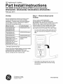
Step I - Remove Bezel (some
models)
Some models (GEH50DEEDSR*,
GEH50DEEDSC* and BEH50DCEHSB*/
RE2H50R10-1NCWW) have a visible screw at the
bottom of the control which allows removal of
control housing. All other models have a bezel
which must be removed to access the screw
securing the control housing to the water heater.
• To remove the bezel pull the right side to the
right and outwards to release the mounting
tabs.
o
° The bottom mounting screw can now be
removed to access rear cover and wiring
connections.
GE Appliances & Lighting
General Electric Company
Louisville, KY 40225
184D1882P002

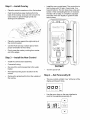
Step 2 - Install Overlay
Place the control console on a firm, flat surface
Peel the protective paper backing from the
back of the overlay. Use care not to touch the
LED window to prevent finger prints and
sticking to the adhesive.
y
/
Place the overlay against the right side lip of
the control housing
Use the RJ45 and top / bottom lips to finish
proper orientation of the overlay.
Firmly press the overlay working from center
out to the edges.
Step 3 - Install the New Control
• Install the control board assembly.
• Connect all wiring.
• Re-mount the control assembly to the water
heater.
Re-install mounting screw at bottom of the
control.
Remove the protective film from the outside of
the overlay.
Install the new control bezel. The control trim is
held in place with 10 tabs. (3 each side, 2 on
top and bottom). The trim does have a top and
bottom. When reinstalling the trim, if reversed,
the tabs will not align. It is helpful to squeeze
the sides of the trim slightly to guide the side
tabs in place.
Turn the power ON.
Step 4 - Set Personality ID
• The new control will blink "ooo" at the top of the
display and beep 3 times.
• Use the arrow keys on the user interface to
scroll to the selected personality ID.
,oC]

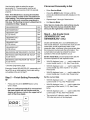
Use the below table to select the proper
personality ID. The personality must be set
correctly for the new service control to operate
properly.
Note: If the Model has a ducting kit installed
use the smaller number in the chart below for
initial setting. The ducted personality number
will not display and cannot be programed in
this step. The Ducting Accessory adjustment is
completed in Step 7 (page 4).
GEH50DEEDSR* 50C
GEH50DEEDSC* 50D
GEH50DFEJSR* 51A
(CCE Active) 54A
GEH50DEEJSC* 52A
(CCE Active) 55A
GEH80DFEJSR* 81A
(CCE Active) 84A
GEH80DEEJSC* 82A
(CCE Active) 85A
BEH50DCEHSB*/RE2H50R10-1 NCWW 50E
BEH50DCEJSB*/RE2H50R10B-1NCWT 53A
(CCE Active) 56A
BEH80DCEJSB*/RE2H80R10B-1NCWT 83A
(CCE Active) 86A
* Denotes Engineering Digit
Example: Model GEH50DEEJSC* personality will
have 52A as an initial setting, the ducted setting
will update at the end of step 7.
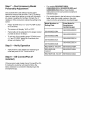
Step 5 - Finish Setting Personality
ID
Press and HOLD the ENTER button until a
tone is heard.
Note: If a valid personality ID is not received
the water heater will not function and the
display will show a circle in the upper half of
each of the three digits.
o'
_C
'_---, Oays
If Incorrect Personality is Set
• Enter Service Mode
Press the MODE button 3 times (until the
previously selected personality displays on the
screen)
Repeat steps 3 through 6 listed above
Exit Service Mode
Note: Service mode entry instructions may be
found in the mini-manual, inside the front
shroud to the right of the control module.
Step 6 - Set Anode Clock
(GEH50DEEJSC* and
GEH80DEEJSC* only)
Models GEH50DEEJSC* and GEH80DEEJSC*
with Anode detection, must have the clock set with
install date, anode replacement date or last
inspection date, whichever is the most recent date,
the consumer must provide this information. The
current date must also be entered for proper
operation of the anode depletion circuit.
Set the Install Date, anode replacement date if it
has been replaced or last inspection date.
• With 00 displayed, use A or v pad to select the
correct install month (1-12), then Press Enter
• With 00 displayed, use A or v pad to select the
correct install day of the month (1-31), then
Press Enter
• With 00 displayed,
correct install year
Set the current date
use A or v pad to select the
(14-20), then Press Enter
With 00 displayed, use A or v pad to select the
current month (1-12), then Press Enter
With 00 displayed, use A or v pad to select the
current day of the month (1-31), then Press
Enter
With 00 displayed, use A or v pad to select the
current year (14-20), then Press Enter
The control will "reboot or reset" and restart.
120 initial set point will be displayed.

Step 7 - Duct Accessory Model
Personality Adjustment
Only activate the CCE setting if it was active
before the control was serviced. The CCE setting
does not need to be active on units with a ducting
kit unless it qualifies for Northern Climate Tier 3
rebates or if the consumerwishes the setting to be
active.
• Press "DOWN Arrow (v)" and "FILTER" button
for 5 seconds.
The screen will display "dUC or CCE".
Personality will be adjusted to the larger ducted
number as shown in Step 3.
To exit out of duct setting press "DOWN Arrow
(v)" and "FILTER" button for 5 seconds, the
screen will display "Std".
Step 8 - Verify Operation
• Verify that the user interface is displaying an
initial set-point of 120 °F and turns on.
Step 9 - GE ConnectPlus (if
installed)
For models GEH50DFEJSRA,
GEH50DEEJSCA, GEH80DFEJSRA and
GEHSODEEJSCA follow the activation
instructions on the consumers smartphone
GeoSpring app.
For models listed in the left column in the below
table, enter the model number in the right
column into the smart 3hone GeoSpring app.
Model Number on Enter Model in
Rating Plate Smartphone
GeoSpring app
GEH50DEEDSRX
GEH50DEEDSRA
GEH50DEEDSRX
GEH50DEEDSRB
GEH50DEEDSCX
GEH50DEEDSCA
GEH50DEEDSCX
GEH50DEEDSCB
RE2H50R10-1NCWW BEH50DCEHSBA
RE2H50R10B- BEH50DCEJSBA
1NCWT
RE2H80R10B-1NCWT BEH80DCEJSBA
If the serviced water heater has a ConnectPlus Wi-
fi module the customer will need to follow the
below direction to connect the GeoSpring to the
smartphone app.

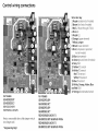
Control wiring connections
For Models:
GEHSODEEDSR*
GEHSODEEDSC*
BEH5ODCEHSB*/
RE2H5ORIO-1NCWW
Notice: some models have a blue jumper wire, it
is no longer used.
* Engineering Digit
For Models
GEHSODFEJSR*
GEHSODEEJSC*
GEH8ODFEJSR*
GEH8ODEEJSC*
RE2HSORIOB-1NCWT /
BEHSODCEJSB* Bradford White
RE2H8ORIOB-1NCWT /
BEH8ODCEJSB* Bradford White
Wire color key
1 Purple (anode)(not all models)
2 Brown (fan)(not all models)
3 Red (L2 Route through CT201)
4 Pink (L2)
5 Purple (L1)
6 Orange (upper element)
7 Yellow Jumper
8 Brown (lower element)
9 Pink (compressor capacitor)
(not all models)
10 Blue (compressor)
11 Green (ground)(not all models)
12 Grey (fan)
13 Yellow (T5 sensor)
14 White (T2sensor)
Red (T3a sensor)
White (T3b sensor)
15 Blue (T4 sensor)
16 White, Orange, Yellow, Blue
and Red (EEV)
17 Orange (Condensate Sensor)

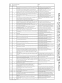
Fault Fault Counts Condition Check
Code Before Code
Displayed Displayed
Control checks to ensure evaporator is free of frost Continuously verifies that Check T3a sensor mounting, wiring and resistance
lO T3a sensor (evaporator inlet temperaturel is greater than 2OFafter 30 minutes Check Electronic Expansion Valve (EEV}operation
FC of run time. Check sealed system for refrigerant leak.
Control checks to ensure evaporator superheat* is OK(controlled by EEV). Check that filter is clean Check T3a, T3b and T5 sensor
Continuously verifies the temperature difference between T3a sensor (evap mounting, wiring and resistance.
10 inlet temp) and T3b sensor (evap outlet temp} is greater than 5F after 30 mins of Check Electronic Expansion Valve (EEV}operation
Fd run time. Control also verifies that T3a is greater than 1OFless than T5 ambient Check sealed system for refrigerant leak.
sensoE
Control checks to ensure the compressor discharge temperature never exceeds Check T4 sensor mounting, wiring and resistance.
10 240F. Continuously verifies that T4 sensor (compressor outlet temperature} is Check Electronic Expansion Valve (EEV}operation
FE less than 240F every minute of run time. Check sealed system for refrigerant leak.
Control checks to ensure the EEV is operating properly and valve rotation is Check Electronic Expansion Valve (EEV}operation.
FF 1O within range Check T3a and T3b sensors mounting, wiring and resistance.
Check sealed system for refrigerant leak.
Control checks to ensure Ambient temperature is within an acceptable range No failure is assumed, but this information is provided for
before starting heat pump. Heat pump operating range is completeness.
FG 10 35°F < [T5 ambient} <120°F If ambient temperature (as viewed by T5
sensor} is outside of this range, the unit will switch to Electric/Standard Mode for
that heating cycle only NO fault code is shown on the display.
Control checks to ensure evaporator superheat is <2O°F AND the EEVposition is Check sealed system for refrigerant leak.
<450 after 30 minutes of run time If outside these limits, this provides an early Check T3a, T3b, T5 sensor mounting, wiring and resistance.
FI* lO indication of a refrigerant leak. (Note: Target superheat is genera@ lO°F, and Check Electronic Expansion Valve (EEV}operation
EEVgenerally operates at a position much lower than 450)
Control checks to ensure that the AC current draw is <= 20.5A while the cam Check lower heating element rated wattage. Element wattage
FJ 10 pressor and lower heating element are both enabled. If current draw is >20.5A,
the compressor will be disabled.
Control checks to ensure that T3a and T3b evaporator inlet and outlet Check T3a, T3b, T5 sensor mounting, wiring and resistance.
FL 10 temperatures are within 2S°F of the T5 ambient temperature 20 Check Electronic Expansion Valve (EEV}operation
minutes after defrost begins.
T2 tank temperature sensor failure Just before compressor starts, control Check T2 sensor mounting, wiring and resistance.
1 checks T2 sensor is within 3OF 170F temperature range Use service mode to monitor T2 sensor temperature.
F2 Control assembly may have failed.
Compressor failure. Control energizes compressor, but current sensor detects Check compressor run capacitoi:
10 no current flow.
F3
F/4 1O Fan Failure Check fan and wiring
T3a sensor (evap inlet temperature} failure. The control detects the thermistor Check T3a sensor mounting, wiring and resistance.
F5 1O output is at or nearly shorted or open circuit. Use service mode to monitor T3a sensor temperature
Control assembly may have failed
T3b sensor (evap outlet temperature} failure. The control detects the thermistor Check T3b sensor mounting, wiring and resistance.
FB 1O output is at or nearly shorted or open circuit. Use service mode to monitor T3b sensor temperature
Control assembly may have failed.
T4 sensor (compressor outlet) failure The control detects the thermistor output Check T4 sensor mounting, wiring and resistance
1O is at or nearly shorted or open circuit Use service mode to monitor T4 sensor temperature.
F7 Control assembly may have failed.
T5 sensor (arnbient temperature} failure. The control detects the thermistor Check T5 sensor mounting, wiring and resistance
F8 1O output is at or nearly shorted or open circuit Use service mode to monitor T5 sensor temperature.
Control assembly may have failed.
Lower heating element failure. Control energizes lower element, but current Check lower heating element and wiring.
F9 1O sensor detects no current flow Use service mode to cycle element and check current draw
Control assembly may have failed.
Upper heating element failure. Control energizes Upper element, but current Check Upper heating element and wiring.
F10 1O sensor detects no current flow. Use service mode to cycle element and check current draw
Control assembly may have failed.
Dry Tank fault. This test is run within the first 22 minutes after the unit has Check to ensure the tank is full of water.
powered on (The compressor is engaged for 20 minutes after a 2minute wait Check T2 sensor mounting, wiring and resistance
for the system to allow the high and low side pressures to equalize.} The tank Use service mode to monitor T2 sensor temperature.
F11 1 temperature, T2, is read and verified it has not risen more than 5 deg F If it has, Control assembly may have failed.
alarm will sound.
Check electrical supply line connections. Voltage should
bAd linE 1 measure either 208 VAC or 240 VAC, depending upon power
(F12) displayed supply. Badline counts stored in "F12" and can be monitored
via the Control when placed in diagnostics mode
Stuck Key fault. This indicates there is a button on the front panel that is stuck Check to see if all buttons are operable.
F13 1 down. This button is inoperable. Other buttons work normally. If the button Control assembly has failed
becomes free, the fault code will clear by itself
Filter LED is on, and audible alarm is sounding Filter is too dirty to enable proper Check to ensure Filter is clean. Filter cleaning instructions are
function of unit. Number of "Dirty Filter" counts are stored in the "F14" code and found in the owner's manual
DirtyFilter 5 can be monitored via the Control when it is placed in Diagnostics Mode. The Repeated dirty filter alarms that do not resolve by cleaning
(F14) evaporator is operating at a colder the filter may be an indication of a fan failure
temperature than the ambient temperature as measured by T5.
DataFlash fault. The microcontroller has detected a problem in the DataFlash Control assembly may have failed
FIB iO (permanent memory storage}
Anode Depleted. Anode LED is on, and the audible alarm is sounding Replace anode rod with GEapproved Anode Depletion
The control has calculated that the anode rod has been mostly anode rod
F16* 1 consumed, or the time in operation has exceeded the replacement
timeline threshold
Anode Depletion miswire condition or shorted to ground The control Check to ensure the tank is full of water. Check anode and
has detected that the anode circuit has a corrosion current (tank) anode wire connections on the board and at the anode
F17* 1 signal <= O25mA. rod Check if either of the T2 wire connections is shorted to
earth ground. Check if anode is shorted to tank
Current transformer miswired. F3, F9,and FIO fault codes have all Check that red L2 wire is through the CT201 current
F18 10 occurred during the same heating cycle transformer on the board If it is, board needs to be replaced
F19 10 Low Line Voltage. Check incoming line voltage.
Check main drain on condensate drain pan. Unblock if
F20 10 necessary Check that the sensor is in the correct position in
is no longer in contact with water, the drain pan, on the screw post near the main drain port
Application Update Failure A problem occurred while updating the control Cyde power and try to complete the update again. If prob
F21 i application, lems persist, replace the control board.
Parametric Data Update Failure. A problem occurred while updating Cycle power and try to complete the update again.
F22 1 parametric data. If problems persist, replace the control board.
Micro A/D Failure The control has detected a microcontroller input port has The control needs to be replaced
F23 iO failed
* on some models
tD
--_ -rl
oo
Sm
cr-Q
rD
-O O
d)
rD
_r_.
O i
BQ
8 n
g.
"O
Q
c___:
d')
o
Z
g.
g.
!
Z
Q
Q
-
 1
1
-
 2
2
-
 3
3
-
 4
4
-
 5
5
-
 6
6


Ask a question and I''ll find the answer in the document
Finding information in a document is now easier with AI
Related papers
Other documents
-
NICOR T3A-22-S-MV-50 Installation guide
-
Bradford White RE2H80T10 User manual
-
Bradford White RE2H80T10 User manual
-
Lochinvar WHP060 User's Information Manual
-
E-Tech WH-75 User manual
-
 Nyle C90w User manual
-
Dimplex AWP 300 LW Datasheet
-
-
 AirTap ATI80 Technical Manual
-
State Water Heaters SHPA-90, SHPA-185, SHPA-250 User manual

