Page is loading ...

z
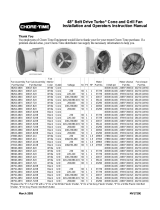
Pit Transition with 24" Fan
Installation and Operators Instruction Manual
Fan and Fan Framing Dimensions
32" [81.3 cm]
36-3/4" [93.3 cm]
36" [91.4 cm]
Shutter Fan
34-13/16" [88.4 cm]
75-1/2" [191.8 cm]
36-3/4" [93.3 cm]
Cone Fan
2" [5.1 cm]
Cone Fan Framing:
Cut a 32" [81.3 cm] x 32" [81.3 cm] opening for the Fan
inlet and create a double treated 2 x 4 frame around it
(See Figure 1).
Shutter Fan Framing:
Cut a 32" [81.3 cm] x 24" [70 cm] opening for the
Fan inlet and create a double treated 2 x 4 frame
around it with an extra 2 x 4 cross piece as shown in
Figure 2.
Figure 1. Cone Fan Framing
3
2
"
[
8
1
.
3
c
m
]
3
2
"
[
8
1
.
3
cm
]
Figure 2. Shutter Fan Framing
3
2
"
[
8
1
.
3
c
m
]
2
4
"
[
7
0
c
m
]
8
"
[
2
0
.
3
c
m
]
2 x 4 Treated Framing
2 x 4 Cross Piece
MV2314A
August 2007

Installation Pit Transition with 24" Fan Installation and Operators Instruction Manual
2
MV2314A
Shutter Fan
Route the Motor Cord (Item 1, Figure 3) down the Motor Mount (Item 2) and use Nylon Ties (Item 3) to
fasten it to the holes in the Motor Mount as shown. Drill a hole in the Transition and exit the cord through
it. Use Caulk or a Water Tight Fitting to seal water out.
Attach the Transition to the 2 x 4 framing with 10 Lag Screws (Item 1, Figure 4) included in parts package.
Installation
Item Description
1 Motor Cord
2 Motor Mount
3 Nylon Tie
Figure 3. Shutter Fan Cord Routing
Item Description
1 Motor Cord
2 Motor Mount
3 Nylon Tie
1
3
2
Caulk or Water Tight Fitting
Item Description
1Lag Screw
1
10 Lag Bolts. (Some Lag Bolts
Hidden by Transition)
Figure 4. Shutter Fan Transition Installation

Pit Transition with 24" Fan Installation and Operators Instruction Manual Installation
MV2314A
3
Cone Fan
Fastening Side Rails
Fasten the Side Rails (Item 1, Figure 5) to the Transition with 1/4-20 Flange Bolts (Item 2) and Nuts (Item
3) as shown.
Fastening the Transition to the Framing and Sliding Fan into Place
Set the Transition on the 2 x 4 framing and attach with 10 Lag Screws (Item 1, Figure 6) included in parts
package. Capture the Fan Flanges between the Side Rails (Item 2) and the Transition (Item 3) and slide the
Fan Assembly down into place as shown.
Item Description
1Side Rail
2 1/4-20 Flange Bolt
3 1/4-20 Flange Nut
Figure 5. Fastening Side Rails
3
2
2
1
Note: 10 Lag Bolts. (Some Lag Bolts
Hidden by Transition)
Item Description
1 Lag Screw (Qty. 10)
2 Side Rail
3 Transition
1
Figure 6. Fastening the Transition and sliding
Fan Assembly into place
2
3

Installation Pit Transition with 24" Fan Installation and Operators Instruction Manual
4
MV2314A
Cord Routing
Route the Motor Cord (Item 1, Figure 7) down the Motor Mount (Item 2) and use Nylon Ties (Item 3) to
fasten it to the holes in the Motor Mount as shown. Drill a hole in the Fan Housing and exit the cord through
it, making sure it does not interfere with the Shutter. Use Caulk or a Water Tight Fitting to seal water out.
Attaching the Cone
Slide the Cone (Item 1, Figure 8) onto the Fan Shroud. Spin the Cone around until the four holes in the
Cone line up with the four holes in the Fan Shroud and Fasten with four Bolts (Item 2) and Flange Nuts
(Item 3) as shown. Install the Grill (Item 4) by inserting it into the notches in the Cone as shown.
Item Description
1 Motor Cord
2 Motor Mount
3 Nylon Tie
Figure 7. Cord Routing
1
3
2
Caulk or Water Tight Fitting
1
4
3
2
Detail Typical
Four Places
Figure 8. Cone Installation
Item Description
1 Cone
2 Bolt
3 Flange Nut
4 Grill

Pit Transition with 24" Fan Installation and Operators Instruction Manual Part Numbers
MV2314A
5
Shutter Fan (Part No. 50501)
Part Numbers
10
9
3
Figure 9. Shutter Fan Part Numbers
Parts numbers and Sub-Assemblies Included in 50501 Shutter Fan
Sub-Assembly Item Description Part No.
24" Fan Shutter w/trim (50500) 1 Shutter Louver 38038-9
2 Pivot Rod 38702-9
24" Panel Fan Assembly (50497)
3 24" Fiberglass Fan Panel 41513
4 Upper Motor Mount 40123
5 Lower Motor Mount 40124
6 Motor 33893
7 1/2" Expanding Bushing 40674
8 24" Fan Blade 40671
Rails and Hardware included in (51159 Kit) 9 Pit Transition Side Rail 51128
Not included in a Sub-Assembly 10 24" Pit Transition 50499
1
2
4
5
6
7
8

Part Numbers Pit Transition with 24" Fan Installation and Operators Instruction Manual
6
MV2314A
Cone Fan (Part Number 51160)
10
9
3
12
Parts numbers and Sub-Assemblies Included in Cone 51160 Fan
Sub-Assembly Item Description Part No.
24" Fan Shutter (Part No. 40602) 1 Shutter Louver 38038-9
2 Pivot Rod 38702-9
24" Panel Fan Assembly (Part No. 40461-22)
also includes 40602 shutter
3 24" Fiberglass Fan Shroud 40177
4 Upper Motor Mount 40123
5 Lower Motor Mount 40124
6 Motor 33893
7 1/2" Expanding Bushing 40674
8 24" Fan Blade 40671
Rails and Hardware included in (51159 Kit) 9 Pit Transition Side Rail 51128
Not included in a Sub-Assembly 10 24" Pit Transition 50499
11 24" Turbo Fan Cone 40179
12 24" Cone Grill 35338
Figure 10. Cone Fan Part Numbers
1
2
4
5
6
7
8
11

Pit Transition with 24" Fan Installation and Operators Instruction Manual Safety Information
MV2314A
7
Carefully read all safety messages in this manual and on your equipment safety signs. Follow recommended
precautions and safe operating practices. Keep safety signs in good condition. Replace missing or damaged safety
signs.
DANGER: Electrical Hazard
Disconnect electrical power before inspecting or servicing equipment Ground all
electrical equipment for safety. All electrical wiring must be done by a qualified
electrician in accordance with local and national electric codes. Ground all non-
current carrying metal parts to guard against electrical shock. With the exception of
motor overload protection, electrical disconnects and over current protection are not
supplied with the equipment.
DANGER: Rotating Fan Blade
Keep Hands away. Disconnect power before servicing. Fan may start
automatically. Do not operate the Fan without the screens in place. Disregard
to these things will cause serious injury including death.
Chore-Time Equipment (“Chore-Time”) warrants each new Chore-Time product manufactured by it to be free from
defects in material or workmanship for one year from and after the date of initial installation by or for the original purchaser.
If such a defect is found by the Manufacturer to exist within the one-year period, the Manufacturer will, at its option, (a)
repair or replace such product free of charge, F.O.B. the factory of manufacture, or (b) refund to the original purchaser the
original purchase price, in lieu of such repair or replacement. Labor costs associated with the replacement or repair of the
product are not covered by the Manufacturer.
Conditions and Limitations
1. The product must be installed by and operated in accordance with the instructions published by the Manufacturer or
Warranty will be void.
2. Warranty is void if all components of the system are not original equipment supplied by the Manufacturer.
3. This product must be purchased from and installed by an authorized distributor or certified representative thereof or the
Warranty will be void.
4. Malfunctions or failure resulting from misuse, abuse, negligence, alteration, accident, or lack of proper maintenance
shall not be considered defects under the Warranty.
5. This Warranty applies only to systems for the care of poultry and livestock. Other applications in industry or commerce
are not covered by this Warranty.
The Manufacturer shall not be liable for any Consequential or Special Damage which any purchaser may suffer or claim
to suffer as a result of any defect in the product. “Consequential” or “Special Damages” as used herein include, but are
not limited to, lost or damaged products or goods, costs of transportation, lost sales, lost orders, lost income, increased
overhead, labor and incidental costs and operational inefficiencies.
THIS WARRANTY CONSTITUTES THE MANUFACTURER’S ENTIRE AND SOLE WARRANTY AND THIS
MANUFACTURER EXPRESSLY DISCLAIMS ANY AND ALL OTHER WARRANTIES, INCLUDING, BUT NOT
LIMITED TO, EXPRESS AND IMPLIED WARRANTIES AS TO MERCHANTABILITY, FITNESS FOR
PARTICULAR PURPOSES SOLD AND DESCRIPTION OR QUALITY OF THE PRODUCT FURNISHED
HEREUNDER.
Chore-Time Distributors are not authorized to modify or extend the terms and conditions of this Warranty in any
manner or to offer or grant any other warranties for Chore-Time products in addition to those terms expressly
stated above. An officer of CTB, Inc. must authorize any exceptions to this Warranty in writing. The
Manufacturer reserves the right to change models and specifications at any time without notice or obligation to
improve previous models.
Safety Information
Warranty

Warranty Pit Transition with 24" Fan Installation and Operators Instruction Manual
8
MV2314A
Made to work.
Built to last.
Note: The original, authoritative version of this manual is the [English] version produced by CTB, Inc. or any of its
subsidiaries or divisions, (hereafter collectively referred to as "CTB"). Subsequent changes to any manual made by
any third party have not been reviewed nor authenticated by CTB. Such changes may include, but are not limited
to, translation into languages other than [English], and additions to or deletions from the original content. CTB
disclaims responsibility for any and all damages, injuries, warranty claims and/or any other claims associated with
such changes, inasmuch as such changes result in content that is different from the authoritative CTB-published
[English] version of the manual. For current product installation and operation information, please contact the
customer service and/or technical service departments of the appropriate CTB subsidiary or division. Should you
observe any questionable content in any manual, please notify CTB immediately in writing to: CTB Legal
Department, P.O. Box 2000, Milford, IN 46542-2000 USA.
Revisions to this Manual
Page No. Description of Change
Various New Manual
Contact your nearby Chore-Time distributor or representative for additional parts and information.
CTB Inc.
P.O. Box 2000 • Milford, Indiana 46542-2000 • U.S.A.
Phone (574) 658-4101 • Fax (877) 730-8825
E-Mail: ctb@ctbinc.com • Internet: http//www.ctbinc.com
Printed in the U.S.A.
/