
Braun Corporation FMVSS No. 403 Quick Reference Installation Sheet 32553 Rev. A
W
A
R
N
I
N
G
8
1
8
2
3
P
u
s
h
T
-
ha
n
dl
e
i
n
f
ul
l
y
a
n
d
m
a
n
u
a
l
l
y
m
ov
e
p
l
a
t
fo
rmi
n
a
n
d
o
u
t
t
o
e
n
g
a
g
e
p
l
a
t
for
m
l
o
c
k
b
e
f
or
e
d
r
i
v
i
n
g
v
e
h
i
c
l
e
.
F
a
i
l
u
re
t
o
lo
c
k
pl
a
t
f
or
m
m
a
y
r
e
s
u
l
t
i
n
u
n
i
n
te
n
d
e
d
p
l
a
t
f
o
r
m
d
e
p
l
o
y
m
e
n
t
.
U
n
i
n
t
e
n
de
d
p
la
t
f
or
m
d
e
pl
o
y
m
e
nt
m
a
y
r
e
s
u
l
t
i
n
s
e
ri
o
us
b
o
d
i
l
y
i
n
j
ur
y
a
n
d/
or
p
r
o
p
e
r
t
y
d
a
m
a
g
e
.
D
o
no
t
r
em
o
ve
!
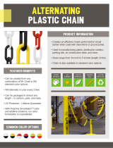
DOOR
OPE
NING
90
CENTER IN
DOOR OPENING
CENTER ACROSS
VEHICLE FRAME
L
C
22-3/8"
22-3/8"
44-3/
4"
1
“DOT — Public Use Lift”
NHTSA Vehicle Physical Requirements
Alternative floor structures are allowed
providing the installed lift system pass-
es all FMVSS 403 requirements.
Figure A
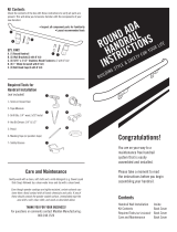
VEHI
CLE
CHASSIS MEMB
ER
16”
Maximum
VEHICLE
CHASSI
S MEMB
ER
All-thread
Mounting
Brackets
Mounting Bracket Requirements:
A maximum distance of 16
" from the
outermost mounting bracket to the
end of the cassette.
All four mounting brackets must be
connected to the framerails.
Vehicle Requirements:
All vehicles with a GVW over 6000 lbs.
and with unmodified OEM framerails.
Clear Door Opening Width
Maximum Floor-to-Ground
B
A
C
Figure B
Door Opening Dimensions
Vehicle lift access door opening
must meet specified dimensions.
Minimum Clear Door
Opening Height
A
B
C
855
NA
43-1/2"
50"
“DOT - Public Use Lift” verifies this platform lift
meets the “public use lift” requirements of FMVSS
No. 403. This lift may be installed on all vehicles
appropriate for the size and weight of the lift, but
must be installed on buses, school buses, and
multi-purpose passenger vehicles other than
motor homes with a gross vehicle weight rating
(GVWR) that exceeds 4,536 kg (10,000 lb).
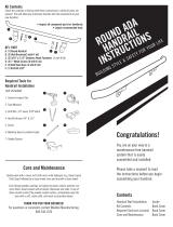
All-Thread
Mounting
Brackets
Engage Platform Manual
Release System: The lift
cable-activated platform
manual release is disengaged
during shipment to prevent
potential drive chain stretch.
Handle the lift with care. En-
gage manual release before
attempting to install (raise, tilt
or move) the lift.
W
A
RNING
Engage manual
release before
attempting to install
(raise, tilt or move)
lift. Failure to do so
may result in serious
bodily injury and/or
property damage.
Figure C
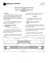
Locate Lift Mounting Brackets
Locate All-Thread Mounting
Brackets
1. Open both doors to 90°.
2. Locate center of door opening
(between doors). Mark the
center point.
3. Transfer center point to the
vehicle frame. Using a front-
to-rear framing member as a
guide, transfer the center point
across chassis to opposite side
front-to-rear framing member
(must be 90° to door opening).
Lift mounting bracket positions
are based on this center line.
4. Measure 22-3/8" to left and
right of the center line to
achieve the 44-3/4" center-to-
center spacing of all-thread
mounting studs.
5. Clamp the mounting brackets
securely in place (all-thread
studs must be vertical).
Braun Corporation FMVSS No. 403
Rev: A
Quick Reference Installation Sheet 32253

Braun Corporation FMVSS No. 403 Quick Reference Installation Sheet 32553 Rev. A
VEHICLE
BO
X FRAME
VEHICLE
CHASSI
S MEMBER
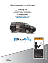
2
Secure Lift
Attach Mounting Brackets to
Vehicle Frame
Mounting bolts must be routed
horizontally through the verti-
cal face of the “L” brackets and
framing members as shown in
Figures D, E and F.
Eight 3/8-16 x 1-1/2" hex bolts
are supplied for bolting the all-
thread mounting brackets to the
frame (two per bracket). Oval
slotted mounting holes are pro-
vided in the mounting brackets
to allow adjustment. Carefully
drill 25/64" (.390") diameter
mounting holes at the center of
the oval mounting slots.
Channel Frame Applications:
Secure mounting bolts as speci-
fied in Figure D.
Box Frame Spacers: Position
tubing spacers as shown at
right to prevent collapsing the
box frame. Carefully drill a
25/64" (.390") diameter mount-
ing hole through one side of the
box frame. Drill a 5/8" (.625")
diameter hole through the
opposite side of box frame to
allow installation of spacer. Cut
spacer tubing to length (equal
to thickness of box frame).
Note: A longer 3/8-16 bolt will
be required for box frame appli-
cations. Secure mounting bolts
as specified in Figures E and F.
All fasteners must meet FM-
VSS 571.403 Section 6.3.
“Box” Framing Member
“Channel” Framing Member
3/8-16 x 1-1/2"
Hex Bolt
All-Thread
Bracket
Box
Framing
Member
Spacer
Flat
Washer
Lock
Washer
Hex
Nut
Flat Washer
3/8-16
Hex Bolt
3/8-16 x 1-1/2"
Hex Bolt
Flat
Washer
Lock
Washer
Hex
Nut
All-Thread
Bracket
Spacer
Flat
Washer
Lock
Washer
Hex
Nut
All-Thread
Bracket
Flat Washer
Figure D
Figure E
5/8"
Diameter
Hole
25/64"
Diameter
Hole
“Box” Framing Member
Figure F
Assembled
Spacer Tubing
Length: Equal
to thickness of
box frame.
Shipping Block Removal:
Wood blocks are placed in the
lift housing to prevent lift dam-
age during shipment. Remove
shipping blocks from platform
and carriage before running
(activating) lift. Refer to
Shipping Block Removal
Instruction 28942.
W
A
R
N
I
N
G
8
1
8
2
3
P
u
sh
T-
h
and
l
e
i
n
f
u
l
l
y
and
m
a
n
u
a
l
l
y
m
o
v
e
p
l
a
t
f
o
rm
i
n
a
n
d
o
u
t
t
o
en
g
a
g
e
pl
a
t
fo
r
m
l
o
ck
b
e
f
o
r
e
d
r
i
v
i
ng
v
eh
i
c
l
e
.
F
ai
l
u
r
e
t
o
l
o
ck
p
l
a
t
f
o
rm
m
a
y
r
es
u
l
t
i
n
u
n
i
n
t
e
n
d
ed
p
l
a
t
f
o
rm
d
ep
l
o
y
men
t
.
U
n
i
n
te
n
d
ed
p
l
a
t
f
o
r
m
d
e
p
l
o
y
m
ent
m
a
y
r
e
sul
t
i
n
s
e
ri
o
u
s
b
o
d
i
l
y
i
nj
u
r
y
a
n
d
/
o
r
p
r
o
per
t
y
da
m
a
g
e
.
D
o
n
o
t
r
e
m
ov
e
!
VEHI
CLE
CHASSIS MEMB
ER
VEHI
CLE
CHASSI
S MEMB
ER
Align mounting clamps
with all-thread studs.
Position and secure lift.
Thread two 3/4" hex jam nuts fully
onto each mounting bracket all-thread
stud. Place one large diameter flat
washer onto each all-thread stud (use
tape to hold in place). See Figures G
and H.
Carefully position lift under vehicle
(aligned with mounting brackets).
Position (slide) the four lift mounting
clamps along the sides of the lift hous-
ing until aligned with mounting bracket
all-thread studs. See Figure G.
Height Adjustment
The lift housing must be
aligned with vehicle chas-
sis. Adjust the 3/4" hex jam
nuts on the all-thread mount-
ing studs at all 4 corners of
the lift until dimensions A, B, C
and D are equal (within 1/16").
See Figure J.
In-Out Positioning
Position the lift to achieve a 2”
overlap between the deployed
inboard barrier and the vehicle
floor.
Figure G
Jam Nuts
Lift Clamp
Jam Nuts
All-Thread
Stud
Flat
Washer
Jam Nuts
Flat Washer
Lift Clamp
Flat Washer
Jam Nuts
Lift
Housing
Lift
Housing
Lift
Clamp
Shift lift and mounting brackets
left-to-right as needed (lift must
be centered in door opening).
Tighten the 3/8" bolts securing
mounting brackets to the frame.
Torque Specifications: 25 to 30
foot pounds.
Figure H
Figure I
Figure J
Note: The two outboard mounting
brackets should be positioned a
maximum of 16” from the end of the
cassette. See Figure J.
Carefully raise lift into position as high
as possible (height adjustment outlined
below). Place one large diameter flat
washer onto each mounting bracket all-
thread stud. Thread two 3/4" hex jam
nuts fully onto each all-thread stud (up
against lift mounting clamp).
VEHI
CLE
CHASSIS MEMB
ER
VEHICLE
CHASSIS MEMBER
A
B
C
D
16”
Max
imum
Dimensions
A, B, C and D
must be equal
(within 1/16
").
Tighten upper set of 3/4" hex
jam nuts (with flat washer)
down to the lift mounting
clamps. Tighten jam nuts.
Torque Specifications: 100
to 120 foot pounds.

Braun Corporation FMVSS No. 403 Quick Reference Installation Sheet 32553 Rev. A
3
Electrical, Hydraulic and Interlock
Pump
Mounting
Bracket
Min.
1-3/4”
to
Wall
Pump
must
face
Out
Mount
Pump
Vertical
1/4-20 x 3/8"
Hex Screws
Lock
Washer
Reinforcement
“L” Bracket
Cable-activated
Manual Release
(from lift)
7/8" Diameter
Mounting Hole
Through-Floor
Cable and Hose
Grommet
(3" Diameter
Mounting Hole)
Figure K
Note:
Remove
plug from
vent tube.
Connect red positive
(+) power cable here
(from Circuit Sentry).
Beeper/Strobe Alarm
and Platform Lights:
Connect harnesses to
mating harnesses at
pump (labeled). Detailed
installation instructions
supplied with kits.
Chassis
5/16"
External Tooth
Star Washer
9/32"
Diameter
Pilot Hole
Thread
Cutting
Screw
Figure L
Ground Cable Mounting
Pump Ground Cable:
One ground cable is pump
mounted. Route this ground cable
through the floor grommet and con-
nect to a vehicle framing member
(see Figure L).
Vehicle Battery Ground Cable:
A ground cable (minimum 2 gauge)
must be connected from vehicle
battery negative post to the same
vehicle framing member the pump
ground cable is attached to.
Ground Cable Corrosion:
When mounting ground
cables, remove undercoat-
ing, dirt, rust, etc. from
framing member around
mounting holes. Apply
protective coating to mount-
ing holes to prevent corro-
sion. Failure to do so will
void warranty of certain
electrical components.
Housing/Carriage Har-
nesses:
Route two main wiring
harnesses from lift through
floor grommet to pump
module. Connect to mat-
ing harnesses at pump.
5/16"
Lag Bolts
(typical - 4)
Note: Seal the
floor cable and
hose grommet
following installa-
tion procedures
(fill with silicone).
Pump Module Mounting
Mount reinforcement “L” bracket
to pump mounting bracket as
shown in Figure K. Secure
pump mounting bracket to floor
using four 5/16" lag bolts.
Check under vehicle for
obstructions before drilling,
cutting holes or installing
floor mounting hardware.
Note: Locate and drill pump
module mounting holes, floor
grommet 3" diameter hole and
manual release 7/8" diameter
hole before mounting pump.
Cable-activated Manual
Release: The T-handle must
be mounted inside the vehicle.
The cable must operate freely
(no kinks or bends). Warning
tag 81823 must remain attached
to the handle. Remove handle
for installation.
Figure N
Note: All
wiring harness
connections
must be
inside the
vehicle.
Vehicle and Lift Interlocks
The pump module is equipped
with a lift interface 9-circuit
connector (female socket).
A mating 9-circuit connector
(male plug) is supplied.
To meet minimum
NHTSA requirements,
connect to vehicle inter-
lock harness as outlined
in Figure N (Steps 1-4).
Optional Interlock Kits
Universal Interlock Kit
30940K is available
for easy interface with
vehicle OEM electronic
signals.
Instrument Panel Display
Kit 30938K provides an
LED Panel Display that
interfaces with Braun
Universal Interlock Kit
30940K.
Note: Detailed installa-
tion instructions are sup-
plied with interlock kits.
Power Cable
Aux.
Bat.
Pos.
Neg.
1/8" x 4" x 4"
Pla
stic
12"
Max.
Circuit
Sen
try
Lead
Cable
Hydraulics:
Remove the plug
from 1/4" diameter
clear vent tube.
See Figure N.
Route hydraulic
hose assembly
through floor
grommet to quick-
disconnect fitting at
lift. Connect hose.
Circuit Sentry:
Install Circuit
Sentry as shown
in Figure M. At-
tach power cable
and lead cable as
detailed.
Figure M
Jumper Wire
Install black jumper wire
last. Install the black jumper
wire in pump Terminal Strip
terminals 6 and 9 after all
other electrical connections
have been made (see Panel
4). The jumper wire supplies
power to the circuit board.
Check floor level and inner roll
stop adjustments as detailed
in Panel 4 before operating
lift with electric pump.
Threshold Warning Sensor:
Connect harness to mating har-
ness at pump module (labeled).
Mat must be installed on a flat
rigid surface. Inboard edge of mat
must be minimum 18" from edge
of finished floor or stepwell.
Disconnect
2
1
Disconnect
and remove
eye terminal
Main Lift Wiring
Harness
es
To Lift
Strobe Alar
m
Pla
tform Lights
(wi
res labeled)
Thre
shold Mat
4
Connect
3
Connect vehicle
interlock signal wires
LIFT S
TOWED
SIGNAL
(Yellow/Light Blue)
VEHICLE SECURE
SIG
NAL
(Gr
ey/Red)
To Interlock

Braun Corporation FMVSS No. 403 Quick Reference Installation Sheet 32553 Rev. A
JKA
Thresho
ld
Sen
sor Mat
U
N
F
O
L
D
FO
L
D
D
O
W
N
U
P
4
Floor Level and Inner Roll Stop Adjustments
Achieving proper floor level positioning of the
platform and inner roll stop requires a combina-
tion of Floor Level switch adjustment and inner
roll stop adjustment. Both are factory set but
must be inspected during installation procedures
(will vary per vehicle application).
Ensure the lift is positioned and secured as speci-
fied above (panels 1 and 2). Adjust the Floor
Level switch first (detailed below). Then, adjust
the inner roll stop as detailed in the service manual
(adjust only if necessary). The inner roll stop must
rest properly on the vehicle floor for wheelchair
entry and exit.
Floor Level Switch
The Floor Level switch stops upward travel of
the platform during the Up function (activated
by the torque tube-mounted Floor Level cam).
Position the lift platform 1" above floor level
using the manual operation system (de-
tailed on opposite side of this sheet). Loosen
the clamp securing the torque tube-mounted
Floor Level cam. Rotate the cam until the
Floor Level switch is activated (cam depresses
switch).
Note: Check the floor level position of the plat-
form and the inner roll stop after powering the
pump. Hydraulic pressure may affect platform
height slightly. Fine tuning adjustment (tweak-
ing) of the Floor Level switch may be required.
Door Operators/Switch, Terminal
Strip and Floor Level Adjustment
Floor Level Switch
Floor Level Cam
Tor qu e Tu be
Cam depressing switch.
Power Door Operators
Figure O
Black
Jumper
12
3 4
5
67
8
9
10
Terminal Strip
The pump-mounted
terminal strip provides
additional inputs and
outputs that can be
used for optional door
operators, beepers,
interlocks, etc. - as
well as the door safety
switch. The black
jumper wire must be
installed in terminals 6
and 9 to supply power
to the circuit board.
C_SW
1
O_RL
2
N/C
3
IN_LK
4
12_V
5
PWR
6
GND
7
F_LV
8
O_SW
9
C_RL
10
To Door Openers
“Close” Trigger
To Door Openers
“Open” Trigger
Door Cutout
Orange
Red
Door Cutout
Black
Blue
Install optional
power door oper-
ators as detailed
in the instructions
supplied with
door operator kit.
Route the wires
to the pump mod-
ule and connect
to the terminal
strip as shown in
Figure P.
Figure P
5
FMVSS 403/404 Certification Checklist
Dual
Outer Barrier
Threshold
Area
Platform
Lighting
Visual and Audible
Threshold Warning
Platform
Inner
Roll Stop
DOT — Public Use Lift
Public use vehicle manufacturers
are responsible for complying with
the lift lighting requirements in Fed-
eral Motor Vehicle Safety Standard
No. 404, Platform Lift Installation in
Motor Vehicles (49 CFR 571.404).
Vehicle movement is prevented unless the lift
door is closed, ensuring the lift is stowed.
Lift operation shall be prevented unless the
vehicle is stopped and vehicle movement is
prevented.
The platform will not fold/stow if occupied.
The outer barrier will not raise if occupied.
The inner roll stop will not raise if occupied.
The operations listed below must be
functionally verified.
Platform movement is prohibited beyond
the position where the inner roll stop is fully
deployed (up).
A visual and audible warning will activate if
the threshold area is occupied when the plat-
form is at least one inch below floor level.
Lift platform movement shall be interrupted
unless the outer barrier is deployed (up).

Braun Corporation FMVSS No. 403 Quick Reference Installation Sheet 32553 Rev. A
Lift Operating Instructions
Lift Operating Instructions
Lift Operating Instructions
Control Switch Functions:
folding handrails and a dual
outer barrier system.
Before lift operation, park the
vehicle on a level surface, away
from vehicular traffic. Place the
vehicle transmission in “Park”
and engage the parking brake.
Open manual doors fully, being
certain the doors are secured in
the fully open position.
It is the responsibility of the lift
operator (attendant) to prop-
erly open, secure and close the
vehicle lift doors, to activate any
auxiliary interlock (if equipped),
to load and unload the wheel-
chair passenger (or standee) on
and off the lift platform, and to
properly activate all lift functions.
In event of power or equipment
failure, refer to the Manual Oper-
ating Instructions section.
W
A
RNING
Whenever a
passenger is on the
platform, the:
• Passenger must
be positioned
fully inside yellow
boundaries
• Wheelchair brakes
must be locked
• Inner roll stop and
outer barrier must
be up.
Failure to do so may
result in serious
bodily injury and/or
property damage.
DOOR STOW
DOWN UP
Note: The instructions out-
lined here are applicable for
“Public-Use” NUVL lift mod-
els equipped with dual
OPEN DOOR(S) AND SECURE
Manually open door(s) fully and
secure.
TO DEPLOY PLATFORM:
1. Stand clear and press the UP
switch until the platform extends
fully. Release switch.
2. Pull handrail detent pins, lift
handrails up to vertical position and
reinsert detent pins.
3. Lift outer barrier to vertical position.
4. Press the UP switch until the plat-
form stops (raises to floor level)
and inner roll stop unfolds to floor
level. Release switch.
TO UNLOAD PASSENGER:
1. Read Note below! Load pas-
senger onto platform and lock
wheelchair brakes.
Note: Passenger must be
positioned fully inside yellow
boundaries and outer barrier must
be UP.
2. Press DOWN switch until the entire
platform reaches ground level and
the outer barrier unfolds fully
(ramp position). Release switch.
3. Unlock wheelchair brakes and
unload passenger from platform.
Note: Outer barrier must be fully
unfolded (ramp position) until the
entire wheelchair (or standee) has
crossed the outer barrier.
UP: From the stowed position, pressing the UP
switch deploys (extends) the platform fully. Release
the UP switch once the platform has extended fully
in order to deploy the outer barrier and handrails.
The platform will continue to raise to floor level if the
UP switch is not released and handrail procedures
may be more difficult (floor level height varies per
vehicle). Pull the handrail detent pins and lift the
handrails to the vertical position. Reinsert the de-
tent pins after the handrails are raised. Lift the outer
barrier to the vertical position. Press the UP switch
until the platform stops (raises to floor level), and the
inner roll stop unfolds to floor level.
From ground level, the UP function will first au-
tomatically raise (rotate) the outer barriers to the
upright (vertical) position. The platform then raises
to floor level position. Note: The lift will not raise
if the outer barrier is not in the UP position (built-in
safety feature).
DOWN: The DOWN function lowers the platform
to ground level and then unfolds the outer barriers
to the ramp (horizontal) position. From the stowed
position, the lift will extend fully and then lower.
STOW: The STOW function raises or lowers the
platform to stow level and then moves the platform
inward (retracts) to the stow position. Handrails
and Outer Barrier: The tall outer barrier and the
handrails must be folded down to the platform
(horizontal) position before stowing (retracting)
the platform. The handrail detent pins must be re-
inserted before stowing the platform also. Note:
The lift will not stow with weight on the platform
(built-in safety feature).
DOOR CLOSE: This function is not applicable
for “Public-Use” NUVL lift models (manual door
system and attendant operated lift).
Note: If any of these functions do not occur as
described, discontinue lift use immediately and
contact your sales representative or call The
Braun Corporation at 1-800-THE LIFT
®
. One of
our national Product Support representatives will
direct you to an authorized service repairman who
will inspect your lift.
Handrails and Dual Outer Barrier:
The folding handrails and tall outer
barrier are manually operated. The
spring-loaded outer barrier (tall barrier)
and the handrails rest on the platform
when the lift is not in use. The outer
barrier must be raised to the vertical
position and the handrails must be
lifted to the vertical position whenever
a passenger is on the platform.
The tall outer barrier and the handrails
must be folded down to the platform
(horizontal) position before stowing
the lift. The handrails fold down onto
the outer barrier to secure the barrier
in the horizontal position.
Each handrail is secured with two de-
tent pins (one pin at the base of each
vertical support tube). The detent pins
must be removed before the handrails
can be folded or unfolded and the
detent pins must be reinserted after
folding or unfolding the handrails.
TO LOAD PASSENGER:
1. Read Notes below! Load pas-
senger onto platform and lock
wheelchair brakes.
Note: Outer barrier must be fully
unfolded (ramp position) until the
entire wheelchair (or standee) has
crossed the outer barrier.
Note: Passenger must be
positioned fully inside yellow
boundaries.
2. Press UP switch to fold outer bar-
rier UP fully (vertical), raise the
platform to floor level and unfold
inner roll stop to floor level. Re-
lease switch.
3. Unlock wheelchair brakes and
unload passenger from platform.
TO STOW PLATFORM:
1. Fold outer barrier down to platform
(horizontal) position.
2. Pull handrail detent pins, fold hand-
rails down to platform (horizontal)
position and reinsert detent pins.
3. Press STOW switch until platform
stops (retracts fully). Release
switch.
CLOSE DOOR(S)
Manually close door(s) fully.
Hand-held Pendant Control:
The hand-held attendent's pendant control is
equipped with four push button switches (DOOR,
STOW, DOWN and UP). The momentary switches
activate the automatic lift functions. Simply press
the switch labeled for the intended function.
When there is power to the lift, the lift function labels
illuminate to identify the functions.

Braun Corporation FMVSS No. 403 Quick Reference Installation Sheet 32553 Rev. A
Manual Operating Instructions
In event of power or equipment
failure, refer to the Manual
Operating Instructions to manu-
ally operate the lift. Refer to the
Lift Operating Instructions for all
normal lift operation procedures
(such as loading and unloading
passengers). Follow all Lift
Operation Safety Precautions
at all times!
Familiarize yourself with the
components necessary to
manually operate the lift. The
T-handle release cable re-
leases and engages the lift
platform to allow the platform
to be manually extended and
retracted. The manual back-
up pump (hand pump) is
used to manually lower and
raise the extended platform.
The location of the power
pack and release cable var-
ies from vehicle to vehicle
(depending on your particular
installation).
Note: Location of power
pack and T-handle varies.
Cable-Activated Platform Manual Release System
POWER
PACK
Hand
Pump
Pump
Handle
Valve
T-Handle
Release
Cable
Manual Operating Instructions
O
P
E
N
C
L
O
S
E
VALVE
O
P
E
N
C
L
O
S
E
OPEN
VALVE
CLOSE
W
A
R
NI
N
G
8
1
8
2
3
Push
T
-handle in ful
l
y
and
manua
lly move plat
fo
rm in
and
out to eng
age
platf
orm
loc
k b
efor
e dr
iving ve
h
icl
e.
Fail
ure
to lock p
lat
f
o
rm
may
res
u
lt in
un
int
ende
d p
lat
form
depl
oymen
t. Un
int
end
e
d
plat
form
d
epl
oyment may
res
u
lt in
se
riou
s
b
odi
ly in
jur
y
and/or pro
p
ert
y d
ama
g
e.
D
o n
o
t
rem
o
ve
!
OUTER BARRIER
Detent
Pin
PLATFORM
Actuato
r
Hairpin
Cotter
OUT (TO EXTEND PLATFORM):
1. Pull T-Handle.
2. Turn T-Handle to lock platform in re-
leased position.
3. Pull platform out.
4. Turn T-Handle.
5. Push T-Handle in.
6. Turn T-Handle to lock platform in en-
gaged position.
DOWN (TO LOWER PLATFORM):
Using hand pump handle, open hand pump
valve (turn counterclockwise). Open 1/2
turn only.
DOWN (TO UNFOLD OUTER BARRIER):
1. Remove hairpin cotter from detent pin.
2. Remove detent pin.
3. Unfold (rotate) barrier down.
UP (TO FOLD OUTER BARRIER):
1. Fold (rotate) barrier up.
2. Insert detent pin.
3. Insert hairpin cotter in detent pin.
UP (TO RAISE PLATFORM):
Using hand pump handle:
1. Close hand pump valve (turn clockwise).
2. Insert handle in pump and stroke.
Note: Close valve before operating
electric pump.
IN (TO STOW PLATFORM):
1. Raise or lower platform to stow level
(follow UP or DOWN procedures).
2. Pull T-Handle.
3. Turn T-Handle to lock platform in re-
leased position.
4. Push platform in.
5. Turn T-Handle.
6. Push T-Handle in.
7. Turn T-Handle to lock platform in en-
gaged position.
W
A
R
N
I
N
G
81
8
2
3
Push
T
-handle in ful
ly
and
man
uall
y mo
ve plat
form in
and out t
o e
ngag
e pl
atfo
rm
loc
k bef
ore
dri
vin
g ve
h
icl
e.
Fail
ur
e t
o lock p
lat
form
ma
y
res
u
lt i
n u
nintended p
latfor
m
deployment. Un
intended
plat
fo
rm dep
loyment may
res
u
lt i
n s
eri
ous bodi
ly injur
y
and/or proper
ty
d
a
m
ag
e.
D
o n
o
t rem
o
ve!
Platform Manual Release Sys-
tem: A cable-activated manual
release system releases and
engages the platform carriage
assembly drive chain to allow the
platform carriage assembly to be
manually moved out (extended)
or moved in (retracted) as need-
ed. A T-handle is provided on the
release cable for activation of the
manual release system (details
follow).
After manually moving the
platform in or out, it is extremely
important that the cable-acti-
vated manual release is positively
re-engaged to secure (lock) the
platform carriage assembly before
loading a passenger on the plat
-
form or before driving the vehicle.
Grasp the outer barrier and move
the platform in and out until the
platform locks (chain release
assembly engages), securing the
platform carriage assembly within
the housing. You will feel the
release mechanism engage.
Failure to manually lock the plat-
form carriage assembly (re-en-
gage the carriage assembly drive
chain) after manual deployment,
will allow the platform to roll in or
out of housing unhindered during
vehicle movement. Failure to lock
the platform will also allow the
platform to roll in or out of hous-
ing unhindered during hand pump
raising and lowering procedures.
After manually releasing
platform, push manual release
T-handle in fully and ensure
platform is locked before driv-
ing lift vehicle. Uncontrolled
and unintentional platform de-
ployment (inadvertent platform
ejection) may result in serious
bodily injury and/or property
damage.
Note: The lift platform must be
pushed back into its carriage
compartment all the way before
reverting back to normal (pow-
ered) operation. When the lift is
W
A
RNING
Push T-handle in fully and
manually move platform in
and out to engage platform
lock before driving vehicle.
Failure to lock platform may
result in unintended platform
deployment. Unintended
platform deployment may
result in serious bodily injury
and/or property damage.
fully extended manually, it does
not activate the proper switches
for normal operation. Returning
(moving) the lift in fully in allows
for proper switch activation.

Braun Corporation FMVSS No. 403 Quick Reference Installation Sheet 32553 Rev. A
Maintenance and Lubrication
750
Cycles
Outer barrier and lower closure pivot points (2)
Outer barrier detent pin pivot points (2)
Inner roll stop hinge pivot points
Inner roll stop linkage pivot points
Lifting arm center and platform pivot points (bear-
ings at all points)
Inspect outer barrier and lower closure for proper
operation
Inspect outer barrier seal and lower closure gasket
Inspect outer barrier detent pin hairpin cotter
Inspect lift for wear, damage or any abnormal
condition
Inspect lift for rattles
Check drive chain tension.
Inspect inner roll stop (bridge plate) and linkage for:
• Proper operation. Roll stop should rest solidly on
floor providing smooth transition.
• Positive securement
• Wear or damage
Check carriage ride height in housing
Check stow height/lifting arm alignment
Inspect wiring harnesses for securement, wear or
other damage
Check lower pan securement
Torque tube pivot bearings (4 places)
Apply Light Oil - See Lubrication Diagram
Apply Light Oil - See Lubrication Diagram
Apply Light Oil - See Lubrication Diagram
Apply Light Oil - See Lubrication Diagram
Apply Light Oil - See Lubrication Diagram
Correct or replace damaged parts.
Resecure, replace or correct as needed
Ensure hairrpin cotter is present and can be
removed and inserted easily. Resecure, replace
or correct as needed.
Correct as needed.
Correct as needed.
Pull out and lock manual release cable. Adjust
chain tension as needed. See Drive Chain Adjust-
ment.
Resecure, replace or correct as needed. See
Inner Roll Stop Adjustment Instructions.
Adjust as needed. See Carriage Ride Height
Adjustment.
Lifting arms should be horizontal, aligned with
each other and aligned with carriage. Adjust as
needed. See Switch Adjustment (Below Stow
Switch).
Resecure, replace or correct as needed
Resecure, replace damaged parts or correct as
needed.
Apply Light Oil - See Lubrication Diagram
Specified (recommended) Available Braun
Lubricant Type Lubricant Amount Part No.
LO - Light Oil
SG - Synthetic Grease
Synthetic Grease Mobiltemp SHC32 12.5 oz.
(Multipurpose) Tube
Light Penetrating Oil LPS2, General Purpose 11 oz.
(30 weight or equivalent) Penetrating Oil Aerosol Can
Stainless Stick Door-Ease 1.68 oz.
Style (tube) Stick (tube)
DE - Door-Ease
15806
28598
15807
Maintenance and Lubrication
Proper maintenance is necessary to ensure safe, trouble-
free operation. Inspecting the lift for any wear, damage
or other abnormal conditions should be a part of all transit
agencies’s daily service program. Simple inspections can
detect potential problems.
The maintenance and lubrication procedures specified in
the following schedule must be performed by a Braun au-
thorized service representative at the scheduled intervals
according to the number of cycles. NHTSA NUVL Series
lifts are equipped with a cycle counter (digital display built
into the electronic control board).
NUVL Series lifts are equipped with hardened pins and
self-lubricating bushings to decrease wear, provide smooth
operation and extend the service life of the lift.
When servicing the lift at the recommended intervals,
inspection and lubrication procedures specified in the pre-
vious sections should be repeated. Clean the components
and the surrounding area before applying lubricants.
LPS2 General Purpose Penetrating Oil is recommended
where Light Oil is called out. Use of improper lubricants
can attract dirt or other contaminants which could result in
wear or damage to the components. Platform components
exposed to contaminants when lowered to the ground may
require extra attention.
Lift components requiring grease are lubricated during as-
sembly procedures. When replacing these components,
be sure to apply grease during installation procedures.
Specified lubricants are available from The Braun Corpora-
tion (part numbers below).
All listed inspection, lubrication and maintenance proce-
dures should be repeated at “750 cycle” intervals following
Maintenance and lu-
brication procedures
must be performed
as specified by an
authorized service
technician.
Failure to do so may
result in serious
bodily injury and/or
property damage.
the scheduled “4500 Cy-
cles” maintenance. These
intervals are a general
guideline for scheduling
maintenance procedures
and will vary according to
lift use and conditions. Lifts
exposed to severe condi-
tions (weather, environ-
ment, contamination, heavy
usage, etc.) may require
inspection and maintenance
procedures to be performed
more often than specified.
Maintenance Indicator:
The Lift Ready green LED
mounted on top of the
pump cover will change color to yellow after every 750 cycles.
The yellow LED will not affect the functions of the lift, but is a
reminder to complete necessary maintenance and lubrication.
Once the lift has been serviced, press the CYCLE button
(located below LCD display on the control board) until the Lift
Ready LED changes back to green. The CYCLE button also
clears the lift cycle count (since last service) but not the lifetime
cycle count.
Discontinue lift use immediately if maintenance and lubrica-
tion procedures are not properly performed, or if there is any
sign of wear, damage or improper operation. Contact your
sales representative or call The Braun Corporation at 1-800-
THE LIFT
®
. One of our national Product Support representa-
tives will direct you to an authorized service technician who will
inspect your lift.
W
A
RNING
Lifting Arm
Pivot Points
LO
Platform Cable-activated
Manual Release System
Inner Roll
Stop Catch
LO
W
A
R
N
I
N
G
8
1
8
2
3
P
u
s
h
T
-h
a
n
d
l
e
i
n
f
u
l
l
y
a
n
d
m
a
n
u
a
l
l
y
m
o
v
e
p
l
a
t
f
o
r
m
i
n
a
n
d
o
u
t
t
o
e
n
g
a
g
e
p
l
a
t
f
o
r
m
l
o
c
k
b
e
f
o
r
e
d
r
i
v
i
n
g
v
e
h
i
c
l
e
.
F
a
i
l
u
r
e
t
o
l
o
c
k
pl
a
t
f
o
r
m
m
a
y
r
e
s
u
l
t
i
n
u
n
i
n
t
e
n
d
e
d
pl
a
t
f
o
r
m
d
e
p
l
o
y
m
e
n
t
.
Un
i
n
t
e
n
d
e
d
p
l
a
t
f
o
r
m
d
e
p
l
o
y
m
e
n
t
m
a
y
r
e
s
u
l
t
i
n
s
e
ri
o
u
s
b
o
di
l
y
i
n
j
u
r
y
a
n
d
/
o
r
p
r
op
e
r
ty
d
a
m
a
g
e
.
D
o
n
o
t
r
e
m
o
v
e
!
Drive Chain and Rollers
LO
Drive Chain
Release Latch
SG
Hydraulic
Cylinder
Pivot
Points
LO
Eccentric
Shaft
Rollers
(bearings)
LO
Tor qu e
Tube
Pivot
Points
LO
Eccentric
Shaft and
Carriage
Rollers
(bearings)
LO
Dual Outer
Barrier (tall)
Pivot Points
LO
Outer Barrier
Detent Pin
LO
Dual Outer
Barrier (short)
and
Lower Closure
Pivot Points
LO
Eccentric
Shaft and
Carriage
Rollers
(bearings)
LO
Inner Roll Stop
Linkage
Pivot Points
LO
Lifting Arm
Pivot Points
LO
Torque Tube
Pivot Points
LO
Hydraulic
Cylinder
Pivot
Points
LO
Inner Roll Stop
Hinge
Pivot Points
and
U
NFO
L
D
F
O
L
D
DO
W
N
U
P
Eccentric
Rolling
Horizontial
Carriage Tube
Slot Area
DE
Lubrication Diagram

Braun Corporation FMVSS No. 403 Quick Reference Installation Sheet 32553 Rev. A
Hydraulic Fluid (Pump) - Check level. Note: Fluid
should be changed if there is visible contamina-
tion. Inspect the hydraulic system (cylinder, hoses,
fittings, seals, etc.) for leaks if fluid level is low.
Inspect lifting arm bushings and pivot pins for vis-
ible wear or damage
Inspect outer barrier pivot pin mounting bolts (2)
Mounting
ecals and ntiskid
Use 5606 aviation fluid only (part 87010R-MILL).
Check fluid level with platform lowered fully.
Fill to within 1-1/2" of the bottom of the fill tube
(neck).
Replace if needed.
ighten or replace if needed
Check to see that the lift is securely anchored to
the vehicle and there are no loose bolts, broken
welds, or stress fractures.
Replace decals if worn, missing or illegible.
Replace antiskid if worn or missing.
Repeat all previously listed inspection, lubrica-
tion and maintenance procedures at 750 cycle
intervals.
Consecutive
750 Cycle
Intervals
1500
Cycles
4500
Cycles
Apply Light Oil - See Lubrication Diagram
Apply Door Ease - See Lubrication Diagram. Ap-
ply to the surface area around both slots and wipe
off ecess
Apply Light Oil - See Lubrication Diagram
Apply Light Oil - See Lubrication Diagram
Apply Synthetic rease - See Lubrication Diagram
Use compressor and nozzle to remove all debris
from housing. Clean outboard lower pan slot and
apply Antisieze to slot before reinstalling pan.
Use clean cloth and solvent to clean tracks. Clean
lower pan slot and apply Antisieze to slot before
reinstalling pan.
Correct or replace damaged parts and/or relubri-
cate. See Drive Chain Adjustment.
Correct or replace damaged parts and/or relubri-
cate.
Ensure T-handle release and cable assembly
operate properly (see Manual Operation). Ensure
carriage can be manually etended and retracted
freely.
Resecure, replace or adjust as needed. See
Switch Adjustment.
Correct, replace damaged parts and/or relubricate.
Resecure, replace or correct as needed.
Resecure, replace damaged parts, lubricate or
correct as needed.
Resecure, replace damaged parts, lubricate or
correct as needed. See Carriage Ride Height
Adjustment.
Resecure, replace or correct as needed.
Resecure, replace or correct as needed.
Tighten, repair or replace if needed.
Resecure, repair or replace if needed.
Carriage and eccentric shaft rollers (bearings)
Lifting arm slots in rolling horizontial carriage arm
tubes
Hydraulic cylinder pivot points (4 per cylinder)
Drive chain and chain rollers
Drive chain release latch mechanism
Deploy lift, remove inboard and outboard lower
pans and blow out housing. Blow off platform also.
Deploy lift, remove inboard and outboard lower
pans and clean housing tracks
Check drive chain tensioner, jam nuts and connect-
ing link for securement and/or misalignment.
Inspect drive chain release latch mechanism for
proper operation, positive securement, wear or
other damage
Inspect platform cable-activated manual release
system (T-handle/cable assembly and carriage
movement)
Inspect limit switches for securement and proper
adjustment
Inspect carriage, lifting arm and eccentric shaft
rollers (bearings) for wear or damage, positive
securement and proper operation
Inspect eternal snap rings (e-clips)
• Carriage roller bearings (4)
• Lower lifting arm pins (5)
• Eccentric shaft track roller bearing (1)
Inspect lower lifting arm pins for wear or damage,
positive securement and proper adjustment
Inspect eccentric shaft pins, bearing mounting
screw, washers and securement hardware for
wear or damage, positive securement and proper
operation
Inspect torque tube cams for securement, wear or
damage
Inspect housing cam brackets for securement,
wear or damage
Inspect cylinder(s), hoses, fittings and hydraulic
connections for wear, damage or leaks
Inspect power cable
Maintenance and Lubrication
Adjustments and Calibration
Adjustment Procedures
Lift Out Switch: The Lift Out Switch stops inward travel of
the carriage/platform during Stow function (activated by the
housing-mounted Lift Out Cam). Move cam in to increase
inward travel. Move cam out to decrease inward travel. LED
D25 will be illuminated when the switch is not contacting the
cam.
Full Out Switch: The Full Out Switch stops outward travel of
the carriage/platform during Deploy (Up/Down) functions (ac-
tivated by the housing-mounted Full Out Cam). Move cam
in to decrease outward travel. Move cam out to increase
outward travel. Carriage rollers must be inside housing a
minimum 1/2". The platform will not raise or lower until this
switch is activated. LED D26 will be illuminated when the
switch is contacting the cam.
Floor Level Switch: LED D28 will be illuminated when the
switch is contacting the cam. Detailed on reverse side.
Below Stow Switch: The Below Stow Switch controls the
height of the carriage/platform before it moves inward during
the Stow function (activated by the torque tube-mounted
Below Stow Cam). Rotate the cam in to decrease platform
height. Rotate the cam out to increase platform height.
Adjust cam so lifting arms are aligned. iew the platform
position in the housing. LED D24 will be illuminated at stow
level and below.
Barrier Down Switch: This platform-mounted switch pro-
hibits the platform from raising unless the outer barrier is in
the full up position. The Up function is prohibited if the outer
barrier detent pin is not fully engaged also. LED D2 will be
illuminated when the switch is not contacting the outer barrier
detent pin.
Drive Chain Adjustment
In event the drive chain sags 1/2" or more, adjust tension
as detailed. Tighten to eliminate visible sag but do not
overtighten.
1. Remove bottom pan.
2. Pull the manual release cable and lock.
. Remove adjustment bolt (tensioner) access cover.
4. Loosen inside jam nut. Secure tensioner and tighten
outside jam nut. Tighten to eliminate visible chain sag but
do not overtighten.
5. Lock jam nuts together making sure the tensioner roller is
horizontial. Release and push the manual cable in fully.
Ensure platform is locked by moving the platform in and
out until chain release assembly engages chain.
Calibration Procedures
Platform Sense Calibration
1. There must be no weight on platform.
2. Press hand-held pendant UP switch to raise platform a
minimum " above stow level.
. Remove pump cover and press and hold control board
mounted CAL. 50 lb. button. hi le pressing the CAL. 50
lb. button, press and hold the hand-held pendant STO
switch (button). The platform will lower to stow level (begin
stow function), and then start to raise. Release CAL. 50 lb.
button immediately when platform starts to raise from stow
level.
4. LED D18 will be illuminated when weight on plat
form prevents stowing.
Ground Sense Calibration
1. Press hand-held pendant DO switch to lower platform
fully to ground level.
2. hi le continuing to press the pendant DO switch, press
and then release control board mounted CALIB. D
SE/OB button.
. Release the pendant DO switch.
4. LED D2 will be illuminated when platform is at ground
level.
Outer Barrier Occupied Calibration
1. Press hand-held pendant DO switch to lower platform
fully to ground level.
2. Once outer barrier is fully unfolded (ramp position), release
the pendant DO switch.
. Press and hold the control board mounted CALIB. D
SE/OB button. hi le holding CALIB. D SE/OB button,
press hand-held pendant UP switch to raise the outer bar-
rier. Be sure to release CALIB. D SE/OB button when
outer barrier reaches approimately half full up (vertical)
position.
Carriage Ride Height Adjustment
The carriage horizontal arms move (roll) in and out of the
housing tracks on roller bearings. Following installation or
etensive lift operation, clearance between horizontal arms
and tracks may diminish. The eccentric shaft mounting plate
allows height adjustment.
Remove eccentric plate mounting screw. Using screwdriver
or small rod, rotate the shaft clockwise to increase carriage
height. Rotate the shaft counterclockwise to decrease carriage
height. Reinstall mounting screw in nearest retainer hole.
Adjust left and right side eccentric shafts (screw positions may
vary from side to side). Adjust height such that horizontal arms
do not contact top or bottom of tracks (align center).
-
 1
1
-
 2
2
-
 3
3
-
 4
4
-
 5
5
-
 6
6
-
 7
7
-
 8
8


Braun FMVSS NO. 403 User manual
- Type
- User manual
- This manual is also suitable for
Ask a question and I''ll find the answer in the document
Finding information in a document is now easier with AI
Related papers
Other documents
-
Dodge H-Box Torque-Arm Assembly Assembly Instructions
-
Mr. Chain 50102 User manual
-
 Mr. Chain 50030-100 User manual
-
Alarm Lock INSIDE BATTERY KIT Installation guide
-
 EZ Handrail EZA6KWR-HB Operating instructions
-
 Wolf Handrail EZA6KWR-HB Installation guide
-
Rockville RHSB8 Owner's manual
-
Hubbell TD09171E_Flat Drop Grommet Installation guide
-
 BraunAbility Entervan XT Maintenance And Service Manual
-
 Federal Signal Corporation TCLF2 User manual


