Cisco WRT610N Owner's manual

Category
Networking
Type
Owner's manual

This manual is also suitable for

USER GUIDE
Simultaneous Dual-N Band
Wireless Router
Model: WRT610N (EU)
About This Guide
i
Simultaneous Dual-N Band Wireless Router
About This Guide
Icon Descriptions
While reading through the User Guide you may see
various icons that call attention to specific items. Below is
a description of these icons:
NOTE: This check mark indicates that there is
a note of interest and is something that you
should pay special attention to while using the
product.
WARNING: This exclamation point indicates
that there is a caution or warning and it is
something that could damage your property or
product.
WEB: This globe icon indicates a noteworthy
website address or e-mail address.
Online Resources
Website addresses in this document are listed without
http:// in front of the address because most current web
browsers do not require it. If you use an older web browser,
you may have to add http:// in front of the web address.
Resource Website
Linksys www.linksys.com
Linksys International www.linksys.com/international
Glossary www.linksys.com/glossary
Network Security www.linksys.com/security
Copyright and Trademarks
Linksys is a registered trademark
or trademark of Cisco Systems, Inc.
and/or its affiliates in the U.S. and
certain other countries. Copyright
© 2008 Cisco Systems, Inc. All rights
reserved. Other brands and product
names are trademarks or registered
trademarks of their respective
holders.
Table of Contents
i
Simultaneous Dual-N Band Wireless Router
Chapter 1: Product Overview 3
Front Panel. . . . . . . . . . . . . . . . . . . . . . . . . . . . . . . . . . . . . . . . . . . . . . . . . . 3
Back Panel . . . . . . . . . . . . . . . . . . . . . . . . . . . . . . . . . . . . . . . . . . . . . . . . . . 3
Chapter 2: Wireless Security Checklist 5
General Network Security Guidelines . . . . . . . . . . . . . . . . . . . . . . . . . . . . . . . . . 5
Additional Security Tips . . . . . . . . . . . . . . . . . . . . . . . . . . . . . . . . . . . . . . . . . 5
Chapter 3: Advanced Conguration 6
Setup > Basic Setup . . . . . . . . . . . . . . . . . . . . . . . . . . . . . . . . . . . . . . . . . . . . 6
Setup > MAC Address Clone. . . . . . . . . . . . . . . . . . . . . . . . . . . . . . . . . . . . . . .11
Setup > Advanced Routing . . . . . . . . . . . . . . . . . . . . . . . . . . . . . . . . . . . . . . .11
Wireless > Basic Wireless Settings . . . . . . . . . . . . . . . . . . . . . . . . . . . . . . . . . . .12
Wireless > Wireless MAC Filter. . . . . . . . . . . . . . . . . . . . . . . . . . . . . . . . . . . . . .16
Wireless > Advanced Wireless Settings . . . . . . . . . . . . . . . . . . . . . . . . . . . . . . . .17
Security > Firewall . . . . . . . . . . . . . . . . . . . . . . . . . . . . . . . . . . . . . . . . . . . . .18
Security > VPN Passthrough. . . . . . . . . . . . . . . . . . . . . . . . . . . . . . . . . . . . . . .18
Storage > Disk . . . . . . . . . . . . . . . . . . . . . . . . . . . . . . . . . . . . . . . . . . . . . . .19
Storage > Media Server. . . . . . . . . . . . . . . . . . . . . . . . . . . . . . . . . . . . . . . . . .20
Storage > FTP Server . . . . . . . . . . . . . . . . . . . . . . . . . . . . . . . . . . . . . . . . . . .21
Storage > Administration . . . . . . . . . . . . . . . . . . . . . . . . . . . . . . . . . . . . . . . .22
Access Restrictions > Internet Access . . . . . . . . . . . . . . . . . . . . . . . . . . . . . . . . .23
Applications and Gaming > Port Range Forwarding . . . . . . . . . . . . . . . . . . . . . . .25
Applications & Gaming > Port Triggering . . . . . . . . . . . . . . . . . . . . . . . . . . . . . .25
Applications and Gaming > DMZ . . . . . . . . . . . . . . . . . . . . . . . . . . . . . . . . . . .26
Applications and Gaming > QoS . . . . . . . . . . . . . . . . . . . . . . . . . . . . . . . . . . . .26
Administration > Management. . . . . . . . . . . . . . . . . . . . . . . . . . . . . . . . . . . . .29
Administration > Log . . . . . . . . . . . . . . . . . . . . . . . . . . . . . . . . . . . . . . . . . . .29
Administration > Diagnostics . . . . . . . . . . . . . . . . . . . . . . . . . . . . . . . . . . . . . .30
Administration > Factory Defaults . . . . . . . . . . . . . . . . . . . . . . . . . . . . . . . . . . .30
Administration > Firmware Upgrade . . . . . . . . . . . . . . . . . . . . . . . . . . . . . . . . .30
Status > Router . . . . . . . . . . . . . . . . . . . . . . . . . . . . . . . . . . . . . . . . . . . . . . .31
Status > Local Network . . . . . . . . . . . . . . . . . . . . . . . . . . . . . . . . . . . . . . . . . .31
Status > Wireless Network . . . . . . . . . . . . . . . . . . . . . . . . . . . . . . . . . . . . . . . .32
Appendix A: Troubleshooting 33
Appendix B: How to Install and Access USB Storage 34
Overview. . . . . . . . . . . . . . . . . . . . . . . . . . . . . . . . . . . . . . . . . . . . . . . . . . .34
How to Install the USB Storage . . . . . . . . . . . . . . . . . . . . . . . . . . . . . . . . . . . . .34
How to Access the USB Storage . . . . . . . . . . . . . . . . . . . . . . . . . . . . . . . . . . . .34
Advanced Configuration (Advanced Users Only). . . . . . . . . . . . . . . . . . . . . . . . . .38
Table of Contents
ii
Simultaneous Dual-N Band Wireless Router
Appendix C: Specications 41
Appendix D: Warranty Information 42
Limited Warranty. . . . . . . . . . . . . . . . . . . . . . . . . . . . . . . . . . . . . . . . . . . . . .42
Appendix E: Regulatory Information 44
FCC Statement . . . . . . . . . . . . . . . . . . . . . . . . . . . . . . . . . . . . . . . . . . . . . . .44
Safety Notices. . . . . . . . . . . . . . . . . . . . . . . . . . . . . . . . . . . . . . . . . . . . . . . .44
Industry Canada Statement . . . . . . . . . . . . . . . . . . . . . . . . . . . . . . . . . . . . . . .44
Avis d’Industrie Canada. . . . . . . . . . . . . . . . . . . . . . . . . . . . . . . . . . . . . . . . . .44
Wireless Disclaimer . . . . . . . . . . . . . . . . . . . . . . . . . . . . . . . . . . . . . . . . . . . .45
Avis de non-responsabilité concernant les appareils sans fil . . . . . . . . . . . . . . . . . .45
Declaration of Conformity with Regard to EU Directive 1999/5/EC (R&TTE Directive) . .46
Wireless Equipment (Wireless-N/G/A/B Products) . . . . . . . . . . . . . . . . . . . . . . . . .47
CE Marking . . . . . . . . . . . . . . . . . . . . . . . . . . . . . . . . . . . . . . . . . . . . . . . . .47
National Restrictions . . . . . . . . . . . . . . . . . . . . . . . . . . . . . . . . . . . . . . . . . . .47
Product Usage Restrictions . . . . . . . . . . . . . . . . . . . . . . . . . . . . . . . . . . . . . . .48
Technical Documents on www.linksys.com/international . . . . . . . . . . . . . . . . . . . .48
User Information for Consumer Products Covered by EU Directive 2002/96/EC on Waste
Electric and Electronic Equipment (WEEE) . . . . . . . . . . . . . . . . . . . . . . . . . . . . . .49
Appendix F: Software License Agreement 53
Software in Linksys Products . . . . . . . . . . . . . . . . . . . . . . . . . . . . . . . . . . . . . .53
Software Licenses . . . . . . . . . . . . . . . . . . . . . . . . . . . . . . . . . . . . . . . . . . . . .53
Chapter 1
Product Overview
3
Simultaneous Dual-N Band Wireless Router
Chapter 1:
Product Overview
Thank you for choosing the Dual-Band Wireless-N Gigabit
Router with Storage Link. The Router lets you access the
Internet via a wireless connection or through one of its four
switched ports. With the built-in storage link, you can easily
add gigabytes of storage space onto your network using
USB 2.0 hard drives, or plug in a USB flash disk to access
your portable data files. The built-in media server streams
music, video and photos from the attached storage device
to any UPnP-compatible media adapter. Configuring the
Router is easy using the provided browser-based utility.
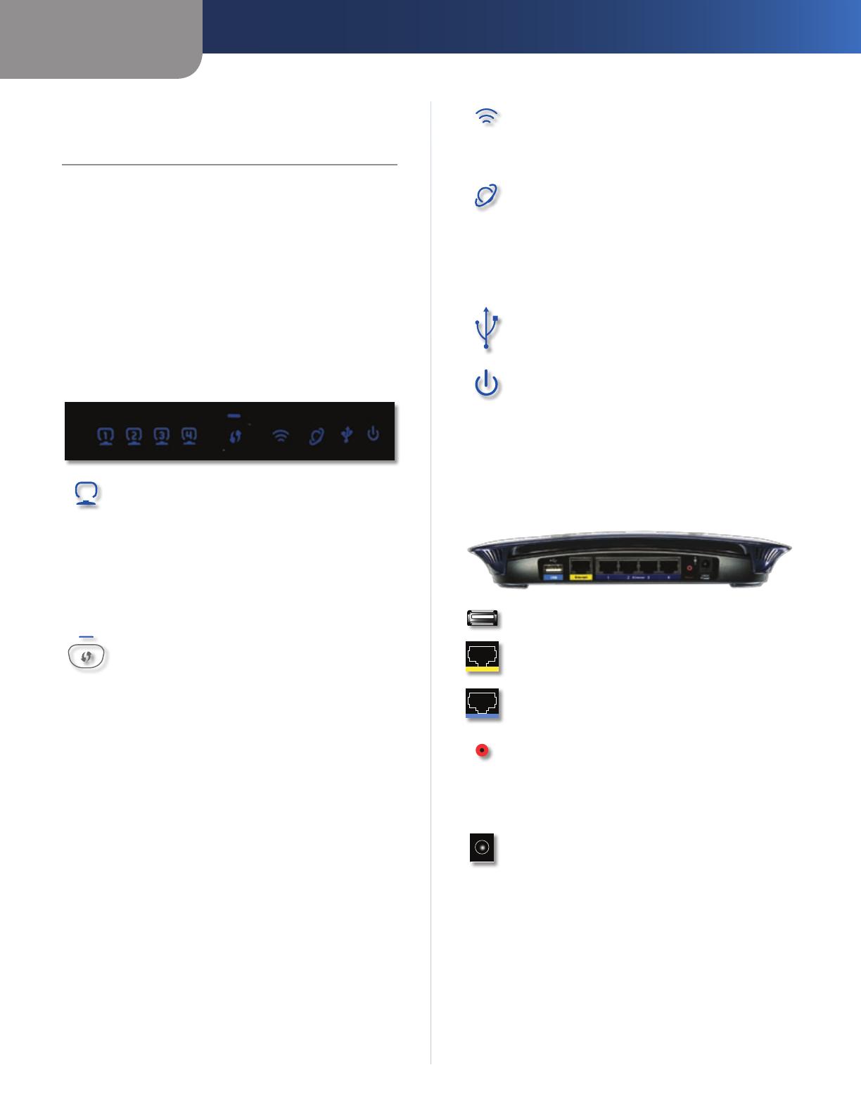
Front Panel
1, 2, 3, 4 (Green/Blue) These numbered LEDs,
corresponding with the numbered ports on the
Routers back panel, serve two purposes. If the
LED is continuously lit, the Router is successfully
connected to a device through that port. A
flashing LED indicates network activity over
that port. The LED lights up Green when it is
connected to 10/100 port and Blue when it is
connected to a gigabit port.
Wi-Fi Protected Setup Button If you have
client devices, such as wireless adapters, that
support Wi-Fi Protected Setup, then you can
use Wi-Fi Protected Setup to automatically
configure wireless security for your wireless
network(s).
To use Wi-Fi Protected Setup, run the Linksys
Easy Link Advisor (LELA) , or refer to the Wireless
> Basic Wireless Settings” section of “Chapter 3:
Advanced Configuration.
Wi-Fi Protected Setup (WPS) LED (Blue/
Amber) The LED flashes blue for two
minutes during the WPS process and lights
up blue when the WPS process is successful.
The LED lights up amber if there is an error
during the Wi-Fi Protected Setup process. Make
sure the client device supports Wi-Fi Protected
Setup. Wait until the LED is off, and then try again.
The LED flashes when a Wi-Fi Protected Setup
session is active. The Router supports one
session at a time. Wait until the LED is solidly lit,
or off before starting the next Wi-Fi Protected
Setup session.
Wireless (Blue) The Wireless LED lights up
when the wireless feature is enabled. If the LED
is flashing, the Router is actively sending or
receiving data over the network.
Internet (Green/Blue) The Internet LED lights
up when there is a connection made through
the Internet port. A flashing LED indicates
network activity over the Internet port. The LED
lights up Green when it is connected to 10/100
port and Blue when it is connected to a gigabit
port.
USB (Blue) The USB LED lights up when a USB
device is attached. If the LED is flashing, the data
is being sent or received through this device.
Power (Blue) The Power LED lights up and will
stay on while the Router is powered on. When
the Router goes through its self-diagnostic
mode during every boot-up, this LED will flash.
When the diagnostic is complete, the LED will
be solidly lit.
Back Panel
USB Port For use with an external hard drive.
Internet The Internet port is where you will
connect your cable or DSL Internet connection.
1, 2, 3, 4 These Ethernet ports (1, 2, 3, 4) connect
the Router to PCs on your wired network and
other Ethernet network devices.
Reset There are two ways to reset the Routers
factory defaults. Either press and hold the Reset
Button for approximately five seconds, or restore
the defaults from Administration > Factory
Defaults in the Routers web-based utility.
Power The Power port is where you will
connect the power adapter.
Chapter 1
Product Overview
4
Simultaneous Dual-N Band Wireless Router
Horizontal Placement
The Router has four rubber feet on its bottom panel. Place
the Router on a level surface near an electrical outlet.
Wall-Mounting Placement
The Router has two wall-mount slots on its bottom
panel. The distance between the slots is 175.56 mm
(6.91 inches).
Two screws are needed to mount the Router.
Suggested Mounting Hardware
2.5-3.0 mm
4-5 mm 1-1.5 mm
Note: Mounting hardware illustrations are not
true to scale.
NOTE: Linksys is not responsible for damages
incurred by unsecure wall-mounting hardware.
Follow these instructions:
Determine where you want to mount the Router. Make 1.
sure that the wall you use is smooth, flat, dry, and
sturdy. Also make sure the location is within reach of
an electrical outlet.
Drill two holes into the wall. Make sure the holes are 2.
175.56 mm (6.91 inches) apart.
Insert a screw into each hole and leave 3 mm 3.
(0.12 inches) of its head exposed.
Maneuver the Router so the wall-mount slots line up 4.
with the two screws.
Place the wall-mount slots over the screws and slide 5.
the Router down until the screws fit snugly into the
wall-mount slots.
175.56 mm
Chapter 2
Wireless Security Checklist
5
Simultaneous Dual-N Band Wireless Router
Chapter 2:
Wireless Security Checklist
Wireless networks are convenient and easy to install, so
homes with high-speed Internet access are adopting them
at a rapid pace. Because wireless networking operates by
sending information over radio waves, it can be more
vulnerable to intruders than a traditional wired network.
Like signals from your cellular or cordless phones, signals
from your wireless network can also be intercepted. Since
you cannot physically prevent someone from connecting
to your wireless network, you need to take some additional
steps to keep your network secure.
1. Change the default wireless
network name or SSID
Wireless devices have a default wireless network name
or Service Set Identifier (SSID) set by the factory. This
is the name of your wireless network, and can be up
to 32 characters in length. Linksys wireless products
use linksys as the default wireless network name. You
should change the wireless network name to something
unique to distinguish your wireless network from other
wireless networks that may exist around you, but do not
use personal information (such as your Social Security
number) because this information may be available for
anyone to see when browsing for wireless networks.
2. Change the default password
For wireless products such as access points and routers,
you will be asked for a password when you want to change
their settings. These devices have a default password set
by the factory. The Linksys default password is admin.
Hackers know these defaults and may try to use them
to access your wireless device and change your network
settings. To thwart any unauthorized changes, customize
the devices password so it will be hard to guess.
3. Enable MAC address filtering
Linksys routers give you the ability to enable Media Access
Control (MAC) address filtering. The MAC address is a
unique series of numbers and letters assigned to every
networking device. With MAC address filtering enabled,
wireless network access is provided solely for wireless
devices with specific MAC addresses. For example, you can
specify the MAC address of each computer in your home
so that only those computers can access your wireless
network.
4. Enable encryption
Encryption protects data transmitted over a wireless
network. Wi-Fi Protected Access (WPA/WPA2) and Wired
Equivalency Privacy (WEP) offer different levels of security
for wireless communication.
A network encrypted with WPA/WPA2 is more secure
than a network encrypted with WEP, because WPA/WPA2
uses dynamic key encryption. To protect the information
as it passes over the airwaves, you should enable the
highest level of encryption supported by your network
equipment.
WEP is an older encryption standard and may be the
only option available on some older devices that do not
support WPA.
General Network Security Guidelines
Wireless network security is useless if the underlying
network is not secure.
Password protect all computers on the network and
individually password protect sensitive files.
Change passwords on a regular basis.
Install anti-virus software and personal firewall
software.
Disable file sharing (peer-to-peer). Some applications
may open file sharing without your consent and/or
knowledge.
Additional Security Tips
Keep wireless routers, access points, or gateways away
from exterior walls and windows.
Turn wireless routers, access points, or gateways
off when they are not being used (at night, during
vacations).
Use strong passphrases that are at least eight characters
in length. Combine letters and numbers to avoid using
standard words that can be found in the dictionary.
WEB: For more information on wireless
security, visit www.linksys.com/security
Chapter 3
Advanced Configuration
6
Simultaneous Dual-N Band Wireless Router
Chapter 3:
Advanced Configuration
After setting up the Router with the Setup Wizard (located
on the CD-ROM), the Router will be ready for use. If youd
like to change its advanced settings, use the Router’s web-
based utility. This chapter describes each web page of the
utility and each page’s key functions. You can access the
utility via a web browser on a computer connected to the
Router.
The web-based utility has these main tabs: Setup, Wireless,
Security, Storage, Access Restrictions, Applications &
Gaming, Administration, and Status. Additional tabs will
be available after you click one of the main tabs.
NOTE: When you first install the Router, you
should use the Setup Wizard on the Setup
CD-ROM. If you want to configure advanced
settings, use this chapter to learn about the
web-based utility.
How to Access the Web-Based Utility
To access the web-based utility, launch the web browser on
your computer, and enter the Routers default IP address,
192.168.1.1 or http://wrt610n.com in the Address field.
Then, press Enter.
A password request screen will appear. (Non-Windows XP
users will see a similar screen.) Leave the User name field
blank. The first time you open the web-based utility, use
the default password admin. (You can set a new password
on the Administration > Management screen.) Click OK to
continue.
Password Screen
Setup > Basic Setup
The first screen that appears is the Basic Setup screen. This
allows you to change the Routers general settings.
Setup > Basic Setup
Language
Language
To use a different language, select one from
the drop-down menu. The language of the web-based
utility will change five seconds after you select another
language.
Click Save Settings to apply your changes, or click Cancel
Changes to cancel your changes.
Internet Setup
The Internet Setup section configures the Router to your
Internet connection. Most of this information can be
obtained through your Internet Service Provider (ISP).
Internet Connection Type
Select the type of Internet connection your ISP provides
from the drop-down menu. The available types are:
Automatic Configuration - DHCP
Static IP
PPPoE
PPTP
L2TP
Telstra Cable
Chapter 3
Advanced Configuration
7
Simultaneous Dual-N Band Wireless Router
Automatic Configuration - DHCP
By default, the Router’s Internet Connection Type is set
to Automatic Configuration - DHCP, which should be
kept only if your ISP supports DHCP or you are connecting
through a dynamic IP address. (This option usually applies
to cable connections.)
Internet Connection Type > Automatic Configuration - DHCP
Static IP
If you are required to use a permanent IP address to
connect to the Internet, select Static IP.
Internet Connection Type > Static IP
IP Address This is the Router’s IP address, when seen from
the Internet. Your ISP will provide you with the IP Address
you need to enter here.
Subnet Mask This is the Routers Subnet Mask, as seen
by users on the Internet (including your ISP). Your ISP will
provide you with the Subnet Mask.
Default Gateway Your ISP will provide you with the
Gateway Address, which is the ISP servers IP address.
DNS Your ISP will provide you with at least one DNS
(Domain Name System) Server IP Address.
PPPoE
Some DSL-based ISPs use PPPoE (Point-to-Point Protocol
over Ethernet) to establish Internet connections. If you are
connected to the Internet through a DSL line, check with
your ISP to see if they use PPPoE. If they do, you will have
to enable PPPoE.
Internet Connection Type > PPPoE
User Name and Password Enter the User Name and
Password provided by your ISP.
Service Name (optional) If provided by your ISP, enter
the Service Name.
Connect on Demand: Max Idle Time You can configure
the Router to cut the Internet connection after it has been
inactive for a specified period of time (Max Idle Time). If
your Internet connection has been terminated due to
inactivity, Connect on Demand enables the Router to
automatically re-establish your connection as soon as you
attempt to access the Internet again. To use this option,
select Connect on Demand. In the Max Idle Time field,
enter the number of minutes you want to have elapsed
before your Internet connection terminates. The default
Max Idle Time is 5 minutes.
Keep Alive: Redial Period If you select this option,
the Router will periodically check your Internet
connection. If you are disconnected, then the Router
will automatically re-establish your connection. To use
this option, select Keep Alive. In the Redial Period field,
you specify how often you want the Router to check
the Internet connection. The default Redial Period is
30 seconds.
PPTP
Point-to-Point Tunneling Protocol (PPTP) is a service that
applies to connections in Europe only.
Internet Connection Type > PPTP
If your ISP supports DHCP or you are connecting through
a dynamic IP address, then select Obtain an IP Address
Automatically. If you are required to use a permanent IP
address to connect to the Internet, then select Specify an
IP Address. Then configure the following:
Internet IP Address This is the Router’s IP address, as
seen from the Internet. Your ISP will provide you with the
IP Address you need to specify here.
Subnet Mask This is the Routers Subnet Mask, as seen
by users on the Internet (including your ISP). Your ISP will
provide you with the Subnet Mask.
Default Gateway Your ISP will provide you with the
Gateway Address, which is the ISP servers IP address.
DNS Your ISP will provide you with at least one DNS
(Domain Name System) Server IP Address.
Server IP Address Your ISP will provide you with the
Server IP Address.
Chapter 3
Advanced Configuration
8
Simultaneous Dual-N Band Wireless Router
User Name and Password Enter the User Name and
Password provided by your ISP.
Connect on Demand: Max Idle Time You can configure
the Router to cut the Internet connection after it has been
inactive for a specified period of time (Max Idle Time). If
your Internet connection has been terminated due to
inactivity, Connect on Demand enables the Router to
automatically re-establish your connection as soon as you
attempt to access the Internet again. To use this option,
select Connect on Demand. In the Max Idle Time field,
enter the number of minutes you want to have elapsed
before your Internet connection terminates. The default
Max Idle Time is 5 minutes.
Keep Alive: Redial Period
If you select this option, the
Router will periodically check your Internet connection. If
you are disconnected, then the Router will automatically
re-establish your connection. To use this option, select Keep
Alive. In the Redial Period field, specify how often you want
the Router to check the Internet connection. The default
value is 30 seconds.
L2TP
L2TP is a service that applies to connections in Israel only.
Internet Connection Type > L2TP
Server IP Address This is the IP address of the L2TP
Server. Your ISP will provide you with the IP Address you
need to specify here.
User Name and Password Enter the User Name and
Password provided by your ISP.
Connect on Demand: Max Idle Time You can configure
the Router to cut the Internet connection after it has been
inactive for a specified period of time (Max Idle Time). If
your Internet connection has been terminated due to
inactivity, Connect on Demand enables the Router to
automatically re-establish your connection as soon as you
attempt to access the Internet again. To use this option,
select Connect on Demand. In the Max Idle Time field,
enter the number of minutes you want to have elapsed
before your Internet connection terminates. The default
Max Idle Time is 5 minutes
Keep Alive: Redial Period If you select this option,
the Router will periodically check your Internet
connection. If you are disconnected, then the Router
will automatically re-establish your connection. To use
this option, select Keep Alive. In the Redial Period field,
you specify how often you want the Router to check
the Internet connection. The default Redial Period is
30 seconds.
Telstra Cable
Telstra Cable is a service that applies to connections in
Australia only.
Internet Connection Type > Telstra Cable
Server IP Address This is the IP address of the Telstra
Cable. Your ISP will provide you with the IP Address you
need to specify here.
User Name and Password Enter the User Name and
Password provided by your ISP.
Optional Settings
Some of these settings may be required by your ISP. Verify
with your ISP before making any changes.
Optional Settings
Host Name/Domain Name These fields allow you to
supply a host and domain name for the Router. Some ISPs,
usually cable ISPs, require these names as identification.
You may have to check with your ISP to see if your
broadband Internet service has been configured with a
host and domain name. In most cases, leaving these fields
blank will work.
MTU MTU is the Maximum Transmission Unit. It specifies
the largest packet size permitted for Internet transmission.
Select Manual if you want to manually enter the largest
packet size that is transmitted. To have the Router select
the best MTU for your Internet connection, keep the
default setting, Auto.
Size When Manual is selected in the MTU field, this option
is enabled. Leave this value in the 1200 to 1500 range. The
default size depends on the Internet Connection Type:
DHCP, Static IP, or Telstra: 1500
PPPoE: 1492
PPTP or L2TP: 1460
Chapter 3
Advanced Configuration
9
Simultaneous Dual-N Band Wireless Router
Network Setup
The Network Setup section changes the settings on the
network connected to the Routers Ethernet ports. Wireless
Setup is performed through the Wireless tab.
Router Address
This presents both the Routers IP Address, Subnet Mask,
and URL Address as seen by your network. The default
Router IP address is 192.168.1.1 and URL address is
http://WRT610N.com.
Router IP Address
Network Address Server Settings (DHCP)
The settings allow you to configure the Routers Dynamic
Host Configuration Protocol (DHCP) server function. The
Router can be used as a DHCP server for your network. A
DHCP server automatically assigns an IP address to each
computer on your network. If you choose to enable the
Routers DHCP server option, make sure there is no other
DHCP server on your network.
Network Address Server Settings (DHCP)
DHCP Server DHCP is enabled by factory default. If you
already have a DHCP server on your network, or you don’t
want a DHCP server, then select Disabled (no other DHCP
features will be available).
Starting IP Address Enter a value for the DHCP server
to start with when is
suing IP addresses. Because the
Routers default IP address is 192.168.1.1, the Starting
IP Address must be 192.168.1.2 or greater, but smaller
than 192.168.1.253. The default Starting IP Address is
192.168.1.100
.
Maximum Number of DHCP Users Enter the maximum
number of PCs that you want the DHCP server to assign
IP addresses to. This number cannot be greater than 253.
The default is 50.
Client Lease Time The Client Lease Time is the amount
of time a network user will be allowed connection to the
Router with their current dynamic IP address. Enter the
amount of time, in minutes, that the user will be “leased”
this dynamic IP address. After the time is up, the user will
be automatically assigned a new dynamic IP address. The
default is 0 minutes, which means one day.
Static DNS (1-3)
The Domain Name System (DNS) is how
the Internet translates domain or website names into
Internet addresses or URLs. Your ISP will provide you with at
least one DNS Server IP Address. If you wish to use another,
enter that IP Address in one of these fields. You can enter up
to three DNS Server IP Addresses here. The Router will use
these for quicker access to functioning DNS servers
.
WINS The Windows Internet Naming Service (WINS)
manages each PC’s interaction with the Internet. If you
use a WINS server, enter that servers IP Address here.
Otherwise, leave this blank.
DHCP Reservation Click DHCP Reservation if you want
to assign a fixed local IP address to a MAC address.
DHCP Reservation
You will see a list of DHCP clients with the following
information: Client Name, Interface, IP Address, and MAC
Address. Click the Select checkbox to reserve a clients IP
address. Then click Add Clients.
If you want to manually assign an IP address, enter the
client’s name in the Enter Client Name field. Enter the IP
address you want it to have in the Assign IP Address field.
Make sure the IP address is between the starting DHCP
servers IP address and maximum number of DHCP users
range. Enter its MAC Address in the To This MAC Address
field. Click Add.
A list of DHCP clients and their fixed local IP addresses will
be displayed at the bottom of the screen. If you want to
remove a client from this list, click Remove.
Chapter 3
Advanced Configuration
10
Simultaneous Dual-N Band Wireless Router
When you finish your changes, click Save Settings to
save your changes. Click Cancel Changes to cancel your
changes. To view the most up-to-date information, click
Refresh. To exit this screen, click Close.
Time Setting
Select the time zone in which your network functions
from this drop-down menu. (You can even automatically
adjust for daylight saving time.)
Time Setting
Click Save Settings to apply your changes, or click Cancel
Changes to cancel your changes.
Setup > DDNS
The Router offers a Dynamic Domain Name System (DDNS)
feature. DDNS lets you assign a fixed host and domain
name to a dynamic Internet IP address. It is useful when
you are hosting your own website, FTP server, or other
server behind the Router.
Before you can use this feature, you need to sign
up for DDNS service with a DDNS service provider,
www.dyndns.org or www.TZO.com. If you do not want to
use this feature, keep the default setting, Disabled.
DDNS
DDNS Service
If your DDNS service is provided by DynDNS.org, then
select DynDNS.org from the drop-down menu. If your
DDNS service is provided by TZO, then select TZO.com.
The features available on the DDNS screen will vary,
depending on which DDNS service provider you use.
DynDNS.org
Setup > DDNS > DynDNS
User Name Enter the User Name for your DDNS account.
Password Enter the Password for your DDNS account.
Host Name The is the DDNS URL assigned by the DDNS
service.
WildCard Select Enabled to enable this feature or
Disabled to disable it.
Internet IP Address The Router’s Internet IP address is
displayed here. Because it is dynamic, it will change.
Status The status of the DDNS service connection is
displayed here.
Update To manually trigger an update, click Update.
Click Save Settings to apply your changes, or click Cancel
Changes to cancel your changes.
TZO.com
Setup > DDNS > TZO
E-mail Address, TZO Password, and Domain
Name Enter the settings of the account you set up with
TZO.
Internet IP Address The Router’s Internet IP address is
displayed here. Because it is dynamic, it will change.
Status The status of the DDNS service connection is
displayed here.
Update To manually trigger an update, click Update.
Click Save Settings to apply your changes, or click Cancel
Changes to cancel your changes.
Chapter 3
Advanced Configuration
11
Simultaneous Dual-N Band Wireless Router
Setup > MAC Address Clone
Every computere hardware device, including the network
adapter of your computer has a unique code called a MAC
address. Some Internet Service Providers (ISPs) require you
to register this address with them in order to access the
Internet. If you do not wish to re-register the MAC address
with your ISP, you may assign the MAC address you have
currently registered with your ISP to the Router with the
MAC Address Clone feature.
Setup > MAC Address Clone
MAC Address Clone
Enabled/Disabled To enable MAC Address cloning,
select Enabled.
User Defined Entry Enter the MAC Address registered
with your ISP here.
Clone Your PC’s MAC Clicking this button will clone the
MAC address of the computer you are using.
Click Save Settings to apply your changes, or click Cancel
Changes to cancel your changes.
Setup > Advanced Routing
This screen is used to set up the Routers advanced
functions. Operating Mode allows you to select the
type(s) of advanced functions you use. Dynamic Routing
automatically adjusts how packets travel on your network.
Static Routing sets up a fixed route to another network
destination.
Setup > Advanced Routing
Advanced Routing
NAT If this Router is hosting your network’s connection
to the Internet, select Enabled. When NAT is disabled,
Dynamic Routing (RIP) will be available as an option.
Dynamic Routing (RIP) This feature enables the Router to
automatically adjust to physical changes in the networks
layout and exchange routing tables with the other
router(s). The Router determines the network packets’
route based on the fewest number of hops between the
source and the destination. This feature is Disabled by
default.
Static Routing
Select Route Entry number To set up a static route
between the Router and another network, select a
number from the drop-down list. (A static route is a pre-
determined pathway that network information must travel
to reach a specific host or network.) Enter the information
described below to set up a new static route. (Click Delete
This Entry to delete a static route.)
Enter Route Name Enter a name for the Route here,
using a maximum of 25 alphanumeric characters.
Destination LAN IP The Destination LAN IP is the address
of the remote network or host to which you want to assign
a static route.
Subnet Mask The Subnet Mask determines which
portion of a Destination LAN IP address is the network
portion, and which portion is the host portion.
Chapter 3
Advanced Configuration
12
Simultaneous Dual-N Band Wireless Router
Gateway This is the IP address of the gateway device that
allows for contact between the Router and the remote
network or host.
Interface This interface tells you whether the Destination
IP Address is on the LAN & Wireless (Ethernet and wireless
networks) or the WAN (Internet).
Click Show Routing Table to view the Static Routes you
have already set up.
Routing Table
Click Save Settings to apply your changes, or click Cancel
Changes to cancel your changes.
Wireless > Basic Wireless Settings
The basic settings for wireless networking are set on this
screen.
Wireless > Basic Wireless Settings
Wireless Configuration
Wireless Configuration Keep the default selection, Wi-
Fi Protected Setup to configure your network using Wi-
Fi Protected Setup. Select Manual to set up your wireless
network your wireless network manually.
Manual
If you set the Wireless Configuration to Manual, the Basic
Wireless Settings screen displays the following fields.
Network Mode (5 GHz) From this drop-down menu, you
can select the wireless standards running on your network.
If you have both Wireless-A and Wireless-N (5GHz) devices
in your network, keep the default setting, Mixed. If you
have only Wireless-A devices, select Wireless-A Only. If
you have only Wireless-N (5GHz) devices, select Wireless-N
Only. If you do not have any Wireless-A and Wireless-N
(5GHz) devices in your network, select Disabled.
Network Mode (2.4 GHz) From this drop-down menu,
you can select the wireless standards running on your
network. If you have both Wireless-B, Wireless-G and
Wireless-N (2.4GHz) devices in your network, keep the
default setting, Mixed. If you have only Wireless-B devices,
select Wireless-B Only. If you have only Wireless-G devices,
select Wireless-G Only. If you have only Wireless-N
(2.4GHz) devices, select Wireless-N Only. If you do not
have any Wireless-B, Wireless-G and Wireless-N (2.4GHz)
devices in your network, select Disabled.
Wireless Network Name (SSID) The SSID is the network
name shared among all points in a wireless network.
The SSID must be identical for all devices in the wireless
network. It is case-sensitive and must not exceed
32 keyboard characters. Make sure this setting is the same
for all points in your wireless network. For added security,
you should change the default SSID to a unique name.
Radio Band (5 GHz) For best performance in a network
using Wireless-A and Wireless-N (5GHz) devices, keep the
default, Auto.
Radio Band (2.4 GHz) For best performance in a network
using Wireless-B, Wireless-G and Wireless-N (2.4GHz)
devices, select Auto. The default is Standard - 20MHz
Channel.
Wide Channel (5 GHz) If you selected Wide - 40MHz
Channel for the Radio Band setting, then this setting will
be available for your primary Wireless-N (5GHz) channel. If
you are not sure which channel to select, keep the default,
Auto (DFS).
Wide Channel (2.4 GHz) If you selected Wide - 40MHz
Channel for the Radio Band setting, then this setting will
be available for your primary Wireless-N (2.4GHz) channel.
If you are not sure which channel to select, keep the
default, Auto.
Standard Channel (5 GHz) Select the channel for
Wireless-A and Wireless-N (5GHz) networking. If you
selected Wide 40MHz Channel for the Radio Band
setting, then the Standard Channel will be a secondary
channel for Wireless-N (5GHz). If you are not sure which
channel to select, keep the default, Auto (DFS).
Chapter 3
Advanced Configuration
13
Simultaneous Dual-N Band Wireless Router
Standard Channel (2.4 GHz) Select the channel for
Wireless-B, Wireless-G and Wireless-N (2.4GHz) networking.
If you selected Wide – 40MHz Channel for the Radio Band
setting, then the Standard Channel will be a secondary
channel for Wireless-N (2.4GHz). If you are not sure which
channel to select, keep the default, Auto.
SSID Broadcast When wireless clients survey the local
area for wireless networks to associate with, they will
detect the SSID broadcast by the Router. To broadcast the
Routers SSID, keep the default setting, Enabled. If you
do not want to broadcast the Router’s SSID, then select
Disabled.
Click Save Settings to apply your changes, or click Cancel
Changes to cancel your changes.
Wi-Fi Protected Setup
There are three methods available. Use the method that
applies to the client device you are configuring.
Wireless > Basic Wireless Settings (Wi-Fi Protected Setup)
NOTE: Wi-Fi Protected Setup configures one
client device at a time. Repeat the instructions
for each client device that supports Wi-Fi
Protected Setup.
Method #1
Use this method if your client device has a Wi-Fi Protected
Setup button.
Click or press the1. Wi-Fi Protected Setup button on
the client device.
Click the 2. Wi-Fi Protected Setup button on this
screen.
After the client device has been configured, click the 3.
OK button. Then refer back to your client device or its
documentation for further instructions.
Method #2
Use this method if your client device has a Wi-Fi Protected
Setup PIN number.
Enter the PIN number from the client device in the1.
field on this screen.
Click the 2. Register button.
After the client device has been configured, click the 3.
OK button. Then refer back to your client device or its
documentation for further instructions.
Method #3
Use this method if your client device asks for the Routers
PIN number.
Enter the PIN number listed on this screen. (It is also 1.
listed on the label on the bottom of the Router.)
After the client device has been configured, click the 2.
OK button. Then refer back to your client device or its
documentation for further instructions.
The Wi-Fi Protected Setup Status, Network Name (SSID),
Security, Encryption, and Passphrase are displayed at the
bottom of the screen.
NOTE: If you have client devices that do not
support Wi-Fi Protected Setup, note the wireless
settings, and then manually configure those
client devices.
Chapter 3
Advanced Configuration
14
Simultaneous Dual-N Band Wireless Router
Wireless > Wireless Security
The Wireless Security settings configure the security of
your wireless network. There are six wireless security
mode options supported by the Router: WPA Personal,
WPA Enterprise, WPA2 Personal, WPA2 Enterprise, RADIUS,
and WEP. (WPA stands for Wi-Fi Protected Access, which
is a security standard stronger than WEP encryption. WEP
stands for Wired Equivalent Privacy, while RADIUS stands
for Remote Authentication Dial-In User Service.) These
six are briefly discussed here. For detailed information
on setting up wireless security networks, refer to
“Chapter 2: Wireless Security.
Wireless Security
Security Mode
Select the security method for your wireless network. If
you do not want to use wireless security, keep the default,
Disabled.
WPA Personal
NOTE: If you are using WPA or WPA2, each
device in your wireless network MUST use the
same WPA or WPA2 method and shared key, or
else the network will not function properly.
WPA Personal
Encryption WPA supports two encryption methods, TKIP
and AES, with dynamic encryption keys. Select the type of
algorithm, TKIP or AES. The default is TKIP.
Passphrase Enter a passphrase of 8-63 characters.
Key Renewal Enter a Key Renewal period, which instructs
the Router how often it should change the encryption
keys. The default Key Renewal period is 3600 seconds.
WPA Enterprise
This option features WPA used in coordination with a
RADIUS server. (This should only be used when a RADIUS
server is connected to the Router.)
WPA Enterprise
Encryption WPA supports two encryption methods, TKIP
and AES, with dynamic encryption keys. Select the type of
algorithm, TKIP or AES. The default is TKIP.
RADIUS Server Enter the IP Address of the RADIUS
server.
RADIUS Port Enter the port number of the RADIUS
server. The default value is 1812.
Shared Key Enter the key shared between the Router
and the server.
Key Renewal Enter a Key Renewal period, which instructs
the Router how often it should change the encryption
keys. The default Key Renewal period is 3600 seconds.
WPA2 Personal
WPA2 Personal
Chapter 3
Advanced Configuration
15
Simultaneous Dual-N Band Wireless Router
Encryption WPA2 supports two encryption methods
with dynamic encryption keys; AES or WPA-TKIP/WPA2-
AES. You must select WPA-TKIP or WPA2-AES to connect
to the Router.
Passphrase Enter a passphrase of 8-63 characters.
Key Renewal Enter a Key Renewal period, which instructs
the Router how often it should change the encryption
keys. The default Key Renewal period is 3600 seconds.
WPA2 Enterprise
This option features WPA2 used in coordination with a
RADIUS server. (This should only be used when a RADIUS
server is connected to the Router.)
WPA2 Enterprise
Encryption WPA2 supports two encryption methods
with dynamic encryption keys; AES or WPA-TKIP/WPA2-
AES. You must select WPA-TKIP or WPA2-AES to connect
to the Router.
RADIUS Server Enter the IP Address of the RADIUS
server.
RADIUS Port Enter the port number of the RADIUS
server. The default value is 1812.
Shared Key Enter the key shared between the Router
and the server.
Key Renewal Enter a Key Renewal period, which instructs
the Router how often it should change the encryption
keys. The default Key Renewal time out period is 3600
seconds.
RADIUS
This option features WEP used in coordination with a
RADIUS server. (This should only be used when a RADIUS
server is connected to the Router.)
RADIUS
IMPORTANT: If you are using WEP encryption,
always each device in your wireless network
MUST use the same WEP encryption method and
encryption key, or else your wireless network will
not function properly.
RADIUS Server Enter the IP Address of the RADIUS
server.
RADIUS Port Enter the port number of the RADIUS
server. The default value is 1812.
Shared Key Enter the key shared between the Router
and the server.
Encryption Select a level of WEP encryption,
64 bits 10 hex digits or 128 bits 26 hex digits. The
default is 64 bits 10 hex digits.
Passphrase Enter a Passphrase to automatically generate
WEP keys. Then click Generate.
Key 1-4 If you did not enter a Passphrase, enter the WEP
key(s) manually.
Tx Key Select a key from the drop-down menu.
Chapter 3
Advanced Configuration
16
Simultaneous Dual-N Band Wireless Router
WEP
WEP is a basic encryption method that is not as secure as
WPA.
WEP
Encryption Select a level of WEP encryption, 64 bits 10
hex digits or 128 bits 26 hex digits. The default is 64 bits
10 hex digits.
Passphrase Enter a Passphrase to automatically generate
WEP keys. Then click Generate.
Key 1-4 If you did not enter a Passphrase, enter the WEP
key(s) manually.
Tx Key Select a key from the drop-down menu.
Click Save Settings to apply your changes, or click Cancel
Changes to cancel your changes.
Wireless > Wireless MAC Filter
Wireless access can be filtered by using the MAC addresses
of the wireless devices transmitting within your network’s
radius.
Wireless > Wireless MAC Filter
Wireless MAC Filter
Access Restriction
Wireless MAC Filter
To filter wireless users by MAC Address,
either permitting or blocking access, click Enabled. If you
do not wish to filter users by MAC Address, keep the default
setting, Disabled
.
Prevent PCs listed below from accessing the wireless
network Select this to block wireless access by MAC
Address. This option is selected by default.
Permit PCs listed below to the wireless network Select
this to allow wireless access by MAC Address. This option
is not selected by default.
MAC Address Filter List
Click the Wireless Client List button to display the
Wireless Client List. It shows computers and other devices
on the wireless network. Click the Save to MAC Address
Filter List checkbox for any device you want to add to
the MAC Address Filter List. Then click the Add button. To
retrieve the most up-to-date information, click the Refresh
button. To exit this screen and return to the Wireless MAC
Filter screen, click the Close button.
Chapter 3
Advanced Configuration
17
Simultaneous Dual-N Band Wireless Router
Wireless Client List
MAC XX Enter the MAC addresses of the devices whose
wireless access you want to control.
Click Save Settings to apply your changes, or click Cancel
Changes to cancel your changes.
Wireless > Advanced Wireless Settings
This Wireless > Advanced Wireless Settings screen is used
to set up the Routers advanced wireless functions. These
settings should only be adjusted by an expert administrator
as incorrect settings can reduce wireless performance.
Wireless > Advanced Wireless Settings
Advanced Wireless
AP Isolation This isolates all wireless clients and wireless
devices on your network from each other. Wireless devices
will be able to communicate with the Router but not
with each other. To use this function, select Enabled. AP
Isolation is disabled by default.
Frame Burst Enabling this option should provide your
network with greater performance, depending on the
manufacturer of your wireless products. To use the Frame
Burst option, select Enabled. The default is Disabled.
Authentication Type The default is set to Auto, which
allows either Open System or Shared Key authentication
to be used. With Open System authentication, the sender
and the recipient do NOT use a WEP key for authentication.
With Shared Key authentication, the sender and recipient
use a WEP key for authentication.
Basic Rate The Basic Rate setting is not one, but a series
of rates at which the Router can transmit. (The Basic Rate
is not the actual rate of data transmission. If you want to
specify the Router’s rate of data transmission, configure
the Transmission Rate setting.) The Router will advertise
its Basic Rate to the other wireless devices in your network,
so they know which rates will be used. The Router will also
advertise that it will automatically select the best rate for
transmission. The default setting is Default, when the
Router can transmit at all standard wireless rates..
Transmission Rate The rate of data transmission should
be set depending on the speed of your wireless network.
You can select from a range of transmission speeds, or you
can select Auto to have the Router automatically use the
fastest possible data rate and enable the Auto-Fallback
feature. Auto-Fallback will negotiate the best possible
connection speed between the Router and a wireless
client. The default value is Auto.
CTS Protection Mode CTS (Clear-To-Send) Protection
Mode should remain disabled unless you are having severe
problems with your wireless products not being able
to transmit to the Router in an environment with heavy
latency wireless traffic. This function boosts the Router’s
ability to catch all wireless transmissions but will severely
decrease performance. The default value is Auto.
Beacon Interval A beacon is a packet broadcast by the
Router to synchronize the wireless network. Enter a value
between 20 and 1000 milliseconds. The Beacon Interval
value indicates the frequency interval of the beacon.The
default value is 100.
DTIM Interval This value, between 3 and 255, indicates
the interval of the Delivery Traffic Indication Message
(DTIM). A DTIM field is a countdown field informing
clients of the next window for listening to broadcast
and multicast messages. When the Router has buffered
broadcast or multicast messages for associated clients, it
sends the next DTIM with a DTIM Interval value. Its clients
hear the beacons and awaken to receive the broadcast
and multicast messages. The default value is 3.
Chapter 3
Advanced Configuration
18
Simultaneous Dual-N Band Wireless Router
Fragmentation Threshold This value specifies the
maximum size for a packet before data is fragmented
into multiple packets. If you experience a high packet
error rate, you may slightly increase the Fragmentation
Threshold. Setting the Fragmentation Threshold too low
may result in poor network performance. Only minor
reduction of the default value is recommended. In most
cases, it should remain at its default value of 2346.
RTS Threshold Should you encounter inconsistent data
flow, only minor reduction of the default value, 2347, is
recommended. If a network packet is smaller than the
preset RTS threshold size, the RTS/CTS mechanism will
not be enabled. The Router sends Request to Send (RTS)
frames to a particular receiving station and negotiates
the sending of a data frame. After receiving an RTS, the
wireless station responds with a Clear to Send (CTS) frame
to acknowledge the right to begin transmission. The RTS
Threshold value should remain at its default value of
2347.
Click Save Settings to apply your changes, or click Cancel
Changes to cancel your changes.
Security > Firewall
The Security > Firewall screen is used to configure a firewall
that can filter out various types of unwanted traffic on the
Routers local network.
Security > Firewall
Firewall
SPI Firewall Protection To use firewall protection,
keep the default selection, Enabled. To turn off firewall
protection, select Disabled.
Internet Filters
Filter Anonymous Internet Requests This feature
makes it more difficult for outside users to work their
way into your network. This feature is selected by default.
Deselect the feature to allow anonymous Internet
requests
.
Filter Multicast Multicasting allows for multiple
transmissions to specific recipients at the same time. If
multicasting is permitted, then the Router will allow IP
multicast packets to be forwarded to the appropriate
computers. It is selected by default. Deselect this feature
to disable it.
Filter Internet NAT Redirection This feature is used to
prevent a local computer from using a URL or Internet
address to access the local server. Select Filter Internet
NAT Redirection to filter Internet NAT redirection. It is not
selected by default.
Filter IDENT (Port 113) This feature keeps port 113 from
being scanned by devices outside of your local network. It
is selected by default. Deselect this feature to disable it.
Web Filters
Filters Select to filter Proxy, Java, ActiveX, and Cookies.
Click Save Settings to apply your changes, or click Cancel
Changes to cancel your changes.
Security > VPN Passthrough
The Security > VPN Passthrough screen allows you to enable
VPN tunnels using IPSec, PPTP, or L2TP protocols to pass
through the Router’s firewall.
Security > VPN Passthrough
VPN Passthrough
IPSec Passthrough Internet Protocol Security (IPSec) is
a suite of protocols used to implement secure exchange
of packets at the IP layer. To allow IPSec tunnels to pass
through the Router, keep the default, Enabled.
PPTP Passthrough Point-to-Point Tunneling Protocol
(PPTP) allows the Point-to-Point Protocol (PPP) to be
tunneled through an IP network. To allow PPTP tunnels to
pass through the Router, keep the default, Enabled.
L2TP Passthrough Layer 2 Tunneling Protocol is the
method used to enable Point-to-Point sessions via the
Internet on the Layer 2 level. To allow L2TP tunnels to pass
through the Router, keep the default, Enabled.
Click Save Settings to apply your changes, or click Cancel
Changes to cancel your changes.
  • Page 1 1
  • Page 2 2
  • Page 3 3
  • Page 4 4
  • Page 5 5
  • Page 6 6
  • Page 7 7
  • Page 8 8
  • Page 9 9
  • Page 10 10
  • Page 11 11
  • Page 12 12
  • Page 13 13
  • Page 14 14
  • Page 15 15
  • Page 16 16
  • Page 17 17
  • Page 18 18
  • Page 19 19
  • Page 20 20
  • Page 21 21
  • Page 22 22
  • Page 23 23
  • Page 24 24
  • Page 25 25
  • Page 26 26
  • Page 27 27
  • Page 28 28
  • Page 29 29
  • Page 30 30
  • Page 31 31
  • Page 32 32
  • Page 33 33
  • Page 34 34
  • Page 35 35
  • Page 36 36
  • Page 37 37
  • Page 38 38
  • Page 39 39
  • Page 40 40
  • Page 41 41
  • Page 42 42
  • Page 43 43
  • Page 44 44
  • Page 45 45
  • Page 46 46
  • Page 47 47
  • Page 48 48
  • Page 49 49
  • Page 50 50
  • Page 51 51
  • Page 52 52
  • Page 53 53
  • Page 54 54
  • Page 55 55
  • Page 56 56
  • Page 57 57
  • Page 58 58
  • Page 59 59
  • Page 60 60
  • Page 61 61
  • Page 62 62
  • Page 63 63
  • Page 64 64
  • Page 65 65
  • Page 66 66

Cisco WRT610N Owner's manual

Category
Networking
Type
Owner's manual
This manual is also suitable for

Ask a question and I''ll find the answer in the document

Finding information in a document is now easier with AI