Losi 1/18 Mini-Desert Truck RTR User manual
- Category
- Remote controlled toys
- Type
- User manual
This manual is also suitable for

Operation Manual
Thank you for choosing the Mini-DT from Losi
®
. This
guide contains the basic instructions for operating
your new Mini-DT. While the Mini-DT is great for rst-
time RC drivers, it does require some mechanical
experience and/or parental supervision for drivers
under 12. It is critical that you read all of the
instructions in order to operate your model correctly
and avoid unnecessary damage. Please take a
moment to look over all the printed materials before
operating your new Mini-DT.

Mini-DT Manual―Page 2
Safety Precautions
This is a sophisticated radio controlled model that must be operated with caution and common sense. Failure to
operate your Mini-DT in a safe and responsible manner could result in damage to the model and property. The
Mini-DT is not intended for use by children without direct adult supervision. Losi and Horizon Hobby shall not be liable
for any loss or damages, whether direct, indirect, special, incidental, or consequential, arising from the use, misuse, or
abuse of this product or any product required to operate it.
• This model is controlled by a radio signal subject to interference from many sources outside your control. This
interference may cause momentary loss of control so it is advisable to always keep some distance in all directions
around your model as a safety margin to avoid collisions.
• Always operate your model in an open area away from cars, trafc and people.
• Avoid running your model in the street where damage can occur.
• Never run your Mini-DT with low transmitter batteries.
• Carefully follow the directions and warnings for this and any optional
support equipment.
• Keep all chemicals, small parts and anything electrical out of the
reach of children.
Warning
This model may only be powered by the stock 6-cell 7.2-volt NiMH battery pack
(LOSB1202) or a 2-cell 7.4-volt LiPo battery pack (LOSB0871). The use of higher
voltage battery packs will cause ESC damage and void any warranty. To use
brushless or 3-cell LiPo batteries you must change the electronics. Consult your
local hobby dealer or check www.losi.com.
Tools and Items You Will Find Handy
• Soft bristle brush for cleaning
• 5.5mm nut driver for the wheel nuts
• #0 or #1 Phillips screwdriver
• LOSA99100 .050” Allen Wrench
Note: Use only Losi tools or other high-quality tools. Use of inexpensive tools
can cause damage to the small screws and parts used on this type of model.
The Radio System
The following is an overview of the various functions and adjustments found on your Losi/Mini-DT radio system. Since
the Mini-DT operates on a radio signal, it is important for you to read and understand about all of these functions
before driving the model.
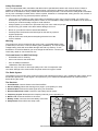
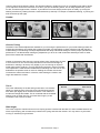
The Receiver
1. On/Off Switch: Controls Power to the Receiver/ESC.
2. Servo Port/Plug: Where the steering servo plugs in (note polarity on case).
3. Antenna Wire: Receives the radio signal from your transmitter.
4. Receiver/ESC Power Lead: Connects to the battery lead for power.
5. Frequency Crystal: Determines the frequency/channel you are operating on.
6. Motor Lead: Connects the ESC to the motor.
7. Battery Leads: Connects the motor battery to the ESC.
8. Setup Button: Enters ESC into setup mode.
1
2
4
8
3
4
5
7

Mini-DT Manual―Page 3
Changing Frequencies/Channels
The Mini-DT radio operates on 27MHz AM and has 6 different frequencies/channels available. Simply put, a frequency
is like a TV channel. The transmitter you hold in your hand is like the TV station and the model with the matching
crystal is like your TV tuned exclusively to the channel of that station. The Mini-DT radio is equipped with changeable
crystals that allow you to change the frequency/channel you operate on. This is especially useful when you want to run
a group of Losi Mini-DT’s at the same time. When changing crystals/channels, you must always replace the crystals
as a matched set with one each going in both the transmitter and the receiver in the truck. Each of the 6 different
channels are numbered and color-coded. Each set includes a unique crystal for the receiver marked (Rx) and one
from the transmitter marked (Tx). The crystals are changed by gently pulling them out, then lining up the two pins of
each new crystal with its socket and carefully pushing them into place. DO NOT force them as damage can occur. If
they do not slide into the socket easily check for bent or misaligned pins.
Channel 1 Brown 26.995MHz (LOSB1094)
Channel 2 Red 27.045MHz (LOSB1095)
Channel 3 Orange 27.095MHz (LOSB1096)
Channel 4 Yellow 27.145MHz (LOSB1097)
Channel 5 Green 27.195MHz (LOSB1098)
Channel 6 Blue 27.255MHz (LOSB1099)
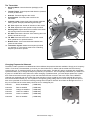
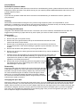
The Transmitter
1. Steering Wheel: Controls direction (left/right) of the
model.
2. Throttle Trigger: Controls speed and direction (forward/
reverse) of the model.
3. Antenna: Transmits signal to the model.
4. On/Off Switch: Turns the power on/off for the
transmitter.
5. Indicator Lights: Green (right) light indicates adequate
battery power. Red (left) indicates signal strength.
6. ST. Trim: Adjusts the “hands off” direction of the model.
7. TH. Trim: Adjusts the motor speed to stop at neutral.
8. Steering Rate: Adjusts amount front wheels move when
the steering wheel is turned left and right.
9. ST. REV: Reverses the function of the steering when the
wheel is turned left or right.
10. TH. REV: Reverses the function of the speed control
when pulled back or pushed forward.
11. Bottom Cover: Covers and holds the batteries that
power the transmitter.
12. Transmitter Crystal: Determines frequency/channel
you transmit on. The receiver must have a matching
frequency/channel to operate.
1
2
7
8
9
10
6
3
4
5
11
12

Mini-DT Manual―Page 4
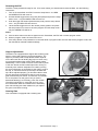
Slipper Adjustments
The Mini-DT is equipped with a slipper device offering both
traction control and protection for the transmission. The
slipper is primarily used to help absorb sudden impacts
on the drive train due to landing big jumps or when using
more powerful aftermarket motors and/or battery packs.
Additionally, it can be used to smooth out the ow of power
to the rear wheels and limit wheel spin when running on
extremely slick surfaces. Adjustment is made by turning
the 3mm adjustment nut clockwise (to the right) to reduce
the slip, or counterclockwise (to the left) to increase the
slip. When adjusted properly, you should be able to hold
the rear tires rmly and barely be able to push the spur
gear forward with your thumb. To track test, turn the Mini-
DT on and place it on the ground. As you push it
backwards allowing it to roll freely, punch the throttle.
The slipper should slip no more than an inch or two
as it accelerates. With the included motor and battery
pack it should slip just a little. Make sure you replace
the gear cover before running.
Steering Rate
Your transmitter is equipped with a steering rate
Resetting the ESC
The ESC comes preset and ready for use. If for some reason you should need to reset the ESC, use the following
instructions:
1. Turn on the transmitter and ESC. Press the setup button – the RED
and GREEN LEDs will come on.
2. Pull the throttle trigger all the way back (full speed) and press the setup
button once – only the GREEN LED will come on.
3. Push the trigger full forward (brake/reverse) and push the setup button
once – only the RED LED will come on.
4. Let the throttle trigger return to the neutral (center) position and press
the setup button once more to save the program and exit setup mode –
only the GREEN LED will be on.
Notes:
A: If the receiver does not receive a signal from the Transmitter, the ESC will not enter program mode.
B: While in program mode, the motor will not run.
C: If the setup button is not pressed for 20 seconds while in program mode, the ESC will exit the program mode, and
the data will be restored to default settings.

Mini-DT Manual―Page 5
control to the left of the steering wheel. This advanced feature, usually found only on competition-type radios, allows
you to adjust the amount the front tires move when you turn the steering wheel. This is really helpful when you are
on slick, as well as high-traction, surfaces. If your Mini-DT turns too sharply and/or spins out easily, try turning the
steering rate down by rotating the knob counterclockwise (to the left). For sharper or additional steering, try turning the
knob clockwise (to the right).
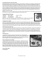
Camber
Camber is the angle of the tires to the racing surface when viewed from the front
or rear of the truck. You want to keep both the front and rear tires straight up
and down or leaning in at the top very slightly. If you are running on carpet or
similar high-traction surfaces, you may nd leaning the tires in a bit more helps.
This adjustment is made with the threaded links extending from the front or rear
bulkhead to the spindle carrier or rear hub. Making the camber rods shorter
increases the camber and lean-in of the tire, while making the camber rods
longer decreases the camber.
Ride Height
This is the height the chassis sits and runs at. Spring spacers included with the Mini-DT, when installed between the
shock top and spring, will increase the pre-load on the spring and raise the chassis. You may want to try this when
running on extremely rough surfaces.
Toe-In
This is the relationship of the left and right side tire to one another.
Ideally you want the front of the tires to be pointed inward toward
each other just slightly when viewed from above. This makes the
model track straight and stable. This is controlled with the threaded
steering rods on either side. As you make them longer you will
increase the toe-in and vice versa.
Chassis Tuning
The Mini-DT has several adjustments available to you for tuning the performance for your needs. Although there are
multiple shock positions and camber link locations provided, as noted above we have built the model with the best
overall settings. The following are simple adjustments and easily maintained settings to assure proper operation and
performance. It is advised when making any adjustment you do so in small increments and always check for other
parts of the chassis that are affected.
Normal More Camber
Normal More Toe-In
Less Rate Full Rate

Mini-DT Manual―Page 6
Service/Repair
Radio/Speed Control & Motor
If you have any problems other than those covered in the troubleshooting section, please call the electronics service
department at (877) 504-0233. They will be able to give your specic problem additional attention and instruct you as
to what needs to be done.
Chassis
If you have any questions other than those covered in the troubleshooting or maintenance sections, please call
(877) 504-0233.
Cleaning
Performance can be hindered if dirt gets in any of the moving suspension parts. Use compressed air, a soft
paintbrush, or toothbrush to remove dust or dirt. Avoid using solvents or chemicals as they can actually wash dirt into
the bearings or moving parts as well as cause damage to the electronics.
Rebuilding the Differential
The gears in the differential will wear over time. The same is true for the outdrives, driveshafts and rear axles. We
suggest using a small rag or paper towel to lay out the parts you remove to make it easier to reassemble.
Disassembly
1. Unplug the motor.
2. Remove the gear cover (three screws).
3. Remove the motor guard screws at the top of the transmission and the two at the
extreme rear bottom of the chassis.
4. Remove the screw attaching the rear shock tower to the transmission and the four
screws at the bottom of the chassis holding the gearbox in place and slide it out of the
chassis
5. Remove the left side of the gearbox by removing the three screws.
6. Remove any shims on the bevel gears and set them aside so they can be reinstalled in
the same location.
7. Carefully remove the large plastic sun gear and the bevel gears on either side of it.
You can use the removed differential assembly as a guide for putting together the
replacement unit (a little Losi Teon grease #LOSA3066 can be
applied for even better performance).
8. Remove the center mounted idler gear from the gearbox. Remove
the shaft and push out the ball bearings from either side. Install
these bearings in the new gear.
Reassembly
Replace the idler gear and shaft into the center of the same right side
of the gearbox. Replace any shims removed from the right bevel gear
and slide it through the lower bearing. Replace any shims that came
off of the left side bevel gear and allow it to slide through the lower
bearing as you put the left gearbox half back into position. Replace
the screws and reinstall the rebuilt gearbox using the steps in reverse
order that were used to remove it.
Changing the Spur Gear
Remove the gear cover by removing the three small screws. If you are replacing the spur gear with one of a different
size (number of teeth), you must rst loosen (do not remove) the two screws that secure the motor and slide it back
slightly. Remove the 3mm nut at the end of the slipper shaft and all of the slipper parts on the outside of the spur gear
as well as the old gear. Place the new spur gear into position and replace the slipper parts. If you have changed the
size of the spur, see Setting the Gear Mesh on the following page. After you have changed the spur gear, you will
have to adjust the slipper as described elsewhere.

Mini-DT Manual―Page 7
Changing the Pinion Gear/Gear Ratio
Before you change the pinion gear ask yourself why you are doing it. In general, if you change to a larger pinion the
top speed will improve but you will see less acceleration and run time. This would only be advisable for really long
track layouts with few tight turns. Changing to a smaller pinion will give you quicker acceleration and possibly a bit
longer run time but a little less top speed. This would be good for short layouts or when running hotter motors. The
pinion on the Mini-DT offers the best balance of both. To change the pinion, remove the gear cover, loosen the motor
screws, and slide the motor back. Use a pair of small needle-nose pliers between the motor plate and back of the
pinion to push the pinion off. Place the new pinion on the end of the motor shaft and, using the at of the pliers or a
similar at tool, push it on to the same position as the one removed. If you have changed the size of the spur, see
Setting the Gear Mesh below.
Warning: When running after-market motors, check with the motor manufacturer for correct gearing. Never over-gear
the motor as it can cause overheating, damaging it and the speed control.
Suggested Mini-DT Gearing
LOSB1089 Mini-DT Motor 14 pinion / 60 spur
LOSB1216 RX-280 BB Motor 14/60
LOSB0837 Insane BB Motor 14/60 or 15/60
Note: If you wish to use a brushless motor like the Losi Xcelorin
™
models you must change the
electronics. Check with your hobby dealer or www.losi.com for complete information.
Setting the Gear Mesh
The motor screws should be slightly loose. Slide the motor forward allowing the pinion gear to mesh with the spur
gear. Snug (not tight) the bottom motor screw and try rocking the spur back and forth. There should be a slight bit of
movement before the motor is forced to turn over. If not, pull the top of the motor back slightly and recheck. If there
is too much slop between the gears, push the top of the motor forward. When set properly the wheels can be spun
forward freely with very little noise. Make sure to tighten both motor screws and replace the gear cover before running.
Radio Replacement/Service
If you have a radio problem please call (877) 504-0233 for customer service. Most likely, unless you have gotten the
components wet, the service technician can help you x the problem over the phone. If the problem is more severe,
you may be asked to send in the truck and transmitter or the entire radio system, which would include the receiver/
speed control unit and steering servo. In some cases, like a broken servo or a speed control that has failed due to
getting wet, your local dealer can sell the replacement component. The following is a complete guide to removing the
system.
Steering Servo
Unplug the servo lead from the receiver. Remove the four small screws that
secure the servo mount/chassis brace to the chassis. Use a screwdriver or small
pliers to pop the steering link off of the servo, so it can be removed. There is no
need to remove the servo mounts on either side as all service can be done with
them on. Replace in the reverse sequence used to remove it.
Receiver/Speed Control (ESC)
Unplug the power lead, motor leads and steering servo. Carefully remove the
antenna wire from the antenna tube. Do not attempt to open the Receiver/ESC
as only factory technicians have the proper tools and parts to make any repairs
necessary. The Receiver/ESC are mounted with double-sided foam tape. Use
your thumb and index nger at the bottom of the front corners to pull them from
the mount. If this is difcult, ask for help. If necessary, carefully use a large at
blade screwdriver between the unit and the mount to pry it loose. Make sure you
remove any left over foam or adhesive before remounting with common servo tape or hobby-type foam tape.
Service/Tech Help
(877) 504-0233

Mini-DT Manual―Page 8
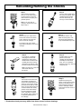
Step 3
Remove the top E-clip from the
shock shaft. Remove the shock
piston. Remove second E-clip.
Remove the old cartridge.
Put a drop of oil on the shock
shaft before installing a new shock
cartridge.
Step 1
After removing the shock,
push up on the lower spring
cup and remove it from the
shaft. Remove the spring and
preload spacers.
Note: If you only wish to
change or ll the shock uid,
skip to step 6.
Step 2
Turn the shock upside down
and remove the black shock
cartridge/shaft assembly
from the shock body by
turning it counterclockwise.
Step 4
Reinstall the lower E-clip.
Slide the shock piston onto
the shock shaft against the
E-clip. Reinstall the top E-clip.
Step 7
Turn the shock over and use
a #0 Phillips screwdriver to
remove the small bleed screw
at the top of the shock. Slowly
push the shock shaft up until it
stops. Excess uid should ow
out of the bleed hole. Slowly
pull the shock shaft halfway
back and replace the bleed
screw. Use pliers to tighten
the cartridge, being careful not
to strip the plastic lobes on
the cartridge.
Step 5
If you plan on completely
changing the shock uid
(suggested), dump out the
old uid from the shock body.
Carefully ll the shock body
with uid to the bottom of the
threads inside the shock body.
Note: Your Mini-DT comes with
30wt shock uid from
the factory.
Step 6
Pull the shaft out so the
piston is next to the
cartridge and reinstall the
assembly into the shock
body, turn in a clockwise
direction until snug—DO NOT
TIGHTEN yet!
Step 8
Replace the spring and
spring cup and test the shock
action for smoothness and
leaks. Retighten the bleed
screw or cartridge if either
leaks. Remount the shock on
your truck.
** Production shock parts may differ from those shown in above drawings.
Rebuilding/Relling the Shocks
Rebuilding/Relling the Shocks
-
 1
1
-
 2
2
-
 3
3
-
 4
4
-
 5
5
-
 6
6
-
 7
7
-
 8
8


Losi 1/18 Mini-Desert Truck RTR User manual
- Category
- Remote controlled toys
- Type
- User manual
- This manual is also suitable for
Ask a question and I''ll find the answer in the document
Finding information in a document is now easier with AI
Related papers
-
Losi 1/10 Speed-T RTR Specification
-
Losi LOS01016T2 Owner's manual
-
-
-
-
Losi Mini 8IGHT-T RTR TRUGGY User manual
-
Losi LOS05020T2 Owner's manual
-
Team Losi LOS03022T2 Owner's manual
-
-
Other documents
-
 Team Losi mini-baja Operating instructions
-
 Team Losi Mini 8IGHT-T User manual
-
 Team Losi mini SCT Operating instructions
-
Team Losi EIGHT-E User manual
-
Apex Digital Scion Racing tC Manual & Catalog
-
Team Losi Racing TLR03009 Owner's manual
-
Duratrax VW Baja Bug User manual
-
-
Kyosho MDW026@Aluminum Motor Holder Set 2 User manual
-


