
1
KU551
Embedded SBC 3.5”
User’s Manual
A45510827

2
Copyright
This publication contains information that is protected by copyright. No part of it may be re-
produced in any form or by any means or used to make any transformation/adaptation without
the prior written permission from the copyright holders.
This publication is provided for informational purposes only. The manufacturer makes no
representations or warranties with respect to the contents or use of this manual and specifi-
cally disclaims any express or implied warranties of merchantability or fitness for any particular
purpose. The user will assume the entire risk of the use or the results of the use of this docu-
ment. Further, the manufacturer reserves the right to revise this publication and make changes
to its contents at any time, without obligation to notify any person or entity of such revisions
or changes.
Changes after the publication’s first release will be based on the product’s revision. The website
will always provide the most updated information.
© 2018. All Rights Reserved.
Trademarks
Product names or trademarks appearing in this manual are for identification purpose only and
are the properties of the respective owners.
FCC and DOC Statement on Class B
This equipment has been tested and found to comply with the limits for a Class B digital
device, pursuant to Part 15 of the FCC rules. These limits are designed to provide reason-
able protection against harmful interference when the equipment is operated in a residential
installation. This equipment generates, uses and can radiate radio frequency energy and, if not
installed and used in accordance with the instruction manual, may cause harmful interference
to radio communications. However, there is no guarantee that interference will not occur in a
particular installation. If this equipment does cause harmful interference to radio or television
reception, which can be determined by turning the equipment off and on, the user is encour-
aged to try to correct the interference by one or more of the following measures:
• Reorient or relocate the receiving antenna.
• Increase the separation between the equipment and the receiver.
• Connect the equipment into an outlet on a circuit different from that to which the receiver
is connected.
• Consult the dealer or an experienced radio TV technician for help.
Notice:
1. The changes or modifications not expressly approved by the party responsible for compli-
ance could void the user’s authority to operate the equipment.
2. Shielded interface cables must be used in order to comply with the emission limits.

3
Copyright .............................................................................................................2
Trademarks ........................................................................................................2
FCC and DOC Statement on Class B .....................................................2
Warranty ..............................................................................................................4
Static Electricity Precautions ......................................................................4
Safety Measures ..............................................................................................4
About the Package .........................................................................................5
Optional Items..................................................................................................5
Before Using the System Board ...............................................................5
Chapter 1 - Introduction .............................................................................6
Specifications ................................................................................................6
Features .......................................................................................................... 7
Chapter 2 - Hardware Installation ������������������������������������������������ 8
Board Layout ................................................................................................. 8
System CPU ...................................................................................................9
Installing the Thermal Solution ...................................................................... 9
Block Diagram ............................................................................................. 10
Mechanical Diagram .................................................................................. 10
System Memory .......................................................................................... 11
Installing the DIMM Module ........................................................................ 11
Jumper Settings ......................................................................................... 12
Clear CMOS Data ........................................................................................ 12
Auto Power-on Select .................................................................................. 13
Backlight Brightness Select .......................................................................... 13
M.2 Signal Select ........................................................................................ 14
Panel Power Select ..................................................................................... 14
Rear Panel I/O Ports ................................................................................. 15
12V DC-in .................................................................................................. 15
Graphics Interfaces ..................................................................................... 16
RJ45 LAN Ports ........................................................................................... 16
USB Ports ................................................................................................... 17
I/O Connectors ........................................................................................... 18
Digital I/O Connector .................................................................................. 18
Front Audio Connector ................................................................................ 18
COM (Serial) Ports ...................................................................................... 19
Standby Power LED .................................................................................... 20
Front Panel Connector ................................................................................ 20
SATA (Serial ATA) Connector ....................................................................... 21
SATA (Serial ATA) Power Connector ............................................................. 21
LVDS LCD Panel Connector ......................................................................... 22
LCD/Inverter Power Connector .................................................................... 22
Cooling Fan Connector ................................................................................ 23
Expansion Slots .......................................................................................... 23
SMBus Connector ....................................................................................... 25
Chassis Intrusion Connector ........................................................................ 25
Battery ....................................................................................................... 26
Chapter 3 - BIOS Setup ��������������������������������������������������������������� 27
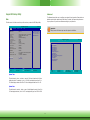
Overview....................................................................................................... 27
Insyde BIOS Setup Utility ........................................................................ 28
Main .......................................................................................................... 28
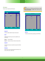
Advanced ................................................................................................... 28
Security ...................................................................................................... 40
Boot........................................................................................................... 40
Exit ............................................................................................................ 41
Updating the BIOS .................................................................................... 42
Notice: BIOS SPI ROM ............................................................................. 42
Chapter 4 - Supported Software ........................................................... 43
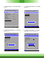
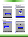
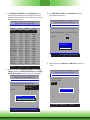
Chapter 5 - Intel AMT Settings .............................................................. 51
Overview ................................................................................51
Enable Intel
®
AMT in the Insyde BIOS .....................................51
Enable Intel
®
AMT in the Intel
®
Management Engine BIOS
Extension (MEBX) Screen ........................................................52
Appendix A - Troubleshooting Checklist ............................................ 65
Table of Contents

4
Warranty
1. Warranty does not cover damages or failures that arised from misuse of the product, in-
ability to use the product, unauthorized replacement or alteration of components and prod-
uct specifications.
2. The warranty is void if the product has been subjected to physical abuse, improper instal-
lation, modification, accidents or unauthorized repair of the product.
3. Unless otherwise instructed in this user’s manual, the user may not, under any circum-
stances, attempt to perform service, adjustments or repairs on the product, whether in or
out of warranty. It must be returned to the purchase point, factory or authorized service
agency for all such work.
4. We will not be liable for any indirect, special, incidental or consequencial damages to the
product that has been modified or altered.
Static Electricity Precautions
It is quite easy to inadvertently damage your PC, system board, components or devices even
before installing them in your system unit. Static electrical discharge can damage computer
components without causing any signs of physical damage. You must take extra care in han-
dling them to ensure against electrostatic build-up.
1. To prevent electrostatic build-up, leave the system board in its anti-static bag until you are
ready to install it.
2. Wear an antistatic wrist strap.
3. Do all preparation work on a static-free surface.
4. Hold the device only by its edges. Be careful not to touch any of the components, contacts
or connections.
5. Avoid touching the pins or contacts on all modules and connectors. Hold modules or con-
nectors by their ends.
Safety Measures
To avoid damage to the system:
• Use the correct AC input voltage range.
To reduce the risk of electric shock:
• Unplug the power cord before removing the system chassis cover for installation or servic-
ing. After installation or servicing, cover the system chassis before plugging the power
cord.
Important:
Electrostatic discharge (ESD) can damage your processor, disk drive and other com-
ponents. Perform the upgrade instruction procedures described at an ESD worksta-
tion only. If such a station is not available, you can provide some ESD protection by
wearing an antistatic wrist strap and attaching it to a metal part of the system chas-
sis. If a wrist strap is unavailable, establish and maintain contact with the system
chassis throughout any procedures requiring ESD protection.

5
About the Package
The package contains the following items. If any of these items are missing or damaged,
please contact your dealer or sales representative for assistance.
• 1 KU551 board
• 1 COM port cable (Length: 300mm, 2 x COM ports)
• 1 Serial ATA data cable (Length: 500mm)
• 1 Serial ATA power cable (Length: 250mm)
• 1 Heat sink (Height: 25.8mm)
Optional Items
• USB port cable (Length: 200mm)
• Power adapter (60W, 12V)
• Heat spreader (Height: 11mm)
• Audio cable (Length: 160mm)
The board and accessories in the package may not come similar to the information listed
above. This may differ in accordance to the sales region or models in which it was sold. For
more information about the standard package in your region, please contact your dealer or
sales representative.
Before Using the System Board
Before using the system board, prepare basic system components.
If you are installing the system board in a new system, you will need at least the following
internal components.
• Storage devices such as hard disk drive, etc.
You will also need external system peripherals you intend to use which will normally include at
least a keyboard, a mouse and a video display monitor.

6
Chapter 1 - Introduction
Specifications
Chapter 1
Chapter 1 Introduction www.d.com
SYSTEM Processor 7th Generation Intel
®
Core
TM
Processors, BGA 1356
Intel
®
Core
TM
i7-7600U Processor, Dual Core, 4M Cache, 2.8GHz (3.9GHz), 15W
Intel
®
Core
TM
i5-7300U Processor, Dual Core, 3M Cache, 2.6GHz (3.5GHz), 15W
Intel
®
Core
TM
i3-7100U Processor, Dual Core, 3M Cache, 2.4GHz, 15W
Intel
®
Celeron
®
Processor 3965U, Dual Core, 2M Cache, 2.2GHz, 15W
Memory One 260-pin SODIMM up to 16GB
Single Channel DDR4 1866/2133MHz
BIOS Insyde SPI 128Mbit
GRAPHICS Controller Intel
®
HD Graphics GT Series
Feature OpenGL 5.0, DirectX 12, OpenCL 2.1
HW Decode: AVC/H.264, MPEG2, VC1/WMV9, JPEG/MJPEG, HEVC/H265, VP8, VP9
HW Encode: AVC/H.264, MPEG2, JPEG, HEVC/H265, VP8, VP9
Display 1 x VGA/DDI
1 x LVDS/eDP
1 x DP++/DDI
VGA: resolution up to 1920x1200 @ 60Hz
LVDS: dual channel 48-bit, resolution up to 1920x1200 @ 60Hz
DP++: resolution up to 4096x2304 @ 60Hz
Triple
Displays
VGA + LVDS + DP++
EXPANSION Interface 1 x Full-size Mini PCIe (PCIe/USB)
1 x M.2 B key 2242 (PCIe/USB2.0/SATA3.0)
1 x Extension I/O connector (available upon request)
AUDIO Audio
Codec
Realtek ALC888
ETHERNET Controller/
Phy
1 x Intel
®
I210AT PCIe (10/100/1000Mbps)
1 x Intel
®
I219LM PCIe with iAMT11.6 (10/100/1000Mbps)
REAR I/O Ethernet 2 x GbE (RJ-45)
USB 4 x USB 3.0
Display 1 x VGA
1 x DP++
INTERNAL I/O Serial 2 x RS-232/422/485 (2.0mm pitch)
USB 2 x USB 2.0 (2.0mm pitch)
Display 1 x LVDS LCD Panel Connector
1 x LCD/Inverter Power
Audio 1 x Audio (Line-out/Mic-in)
SATA 1 x SATA 3.0 (up to 6Gb/s)
1 x SATA Power
DIO 1 x 8-bit DIO
SMBus 1 x SMBus
WATCHDOG TIMER Output & Interval System Reset, Programmable via Software from 1 to 255 Seconds
SECURITY TPM fTPM 2.0
POWER Type Single 12V +/-5% DC
Connector Right Angle Connector (4-pin)
DC Jack (available upon request)
Vertical Type Connector (4-pin) (available upon request)
Consumption Idle: i7-7600U:12V @ 0.9A (10.8Watt)
Max.: i7-7600U:12V @ 3.2A (38.5Watt)
RTC Battery CR2032 Coin Cell
OS SUPPORT Microsoft Windows 10 IoT Enterprise 64-bit
Linux Ubuntu 16.04
Yocto
ENVIRONMENT Temperature Operating: 0 to 60°C (Opt. -20 to 70 °C)
Storage: -40 to 85°C
Humidity Operating: 5 to 90% RH
Storage: 5 to 90% RH
MTBF 477,146 hrs @ 25°C; 277,228 hrs @ 45°C; 172,875 hrs @ 60°C
MECHANICAL Dimensions 3.5" SBC Form Factor
146mm (5.75") x 102mm (4.02")
Height PCB: 1.6mm
Top Side: 16.3mm, Bottom Side: 4.0mm
CERTIFICATIONS CE, FCC, RoHS

7
Chapter 1
Chapter 1 Introduction www.d.com
Features
• Watchdog Timer
The Watchdog Timer function allows your application to regularly “clear” the system at the set
time interval. If the system hangs or fails to function, it will reset at the set time interval so
that your system will continue to operate.
• DDR4
DDR4 delivers increased system bandwidth and improves performance. The advantages of
DDR4 provide an extended battery life and improve the performance at a lower power than
DDR3/DDR2.
• Graphics
The integrated Intel
®
HD graphics engine delivers an excellent blend of graphics performance
and features to meet business needs. It provides excellent video and 3D graphics with out-
standing graphics responsiveness. These enhancements deliver the performance and compat-
ibility needed for today’s and tomorrow’s business applications. Supports 1 VGA/DDI, 1 LVDS/
eDP and 1 DP++/DDI interfaces for triple display outputs.
• Serial ATA
Serial ATA is a storage interface that is compliant with SATA 1.0a specification. With speed of
up to 6Gb/s (SATA 3.0), it improves hard drive performance faster than the standard parallel
ATA whose data transfer rate is 100MB/s.
• Gigabit LAN
Intel
®
I210AT PCI Express Gigabit Ethernet controller and Intel
®
I219LM PCI Express Gigabit
Ethernet controller with iAMT11.6 support up to 1Gbps data transmission.
• Audio
The Realtek ALC888 audio codec provides 2.1-channel High Definition audio output.
• Power Failure Recovery
When power returns after an AC power failure, you may choose to either power-on the system
manually or let the system power-on automatically.
• USB
The system board supports the new USB 3.0. It is capable of running at a maximum transmis-
sion speed of up to 5 Gbit/s (625 MB/s) and is faster than USB 2.0 (480 Mbit/s, or 60 MB/s)
and USB 1.1 (12Mb/s). USB 3.0 reduces the time required for data transmission, reduces
power consumption, and is backward compatible with USB 2.0. It is a marked improvement in
device transfer speeds between your computer and a wide range of simultaneously accessible
external Plug and Play peripherals.
Important:
The 5V_standby power source of your power supply must support ≥720mA.
• Wake-On-USB (Optional)
This function allows you to use a USB keyboard or USB mouse to wake up a system from the
S3 (STR - Suspend To RAM) state.
• ACPI STR
The system board is designed to meet the ACPI (Advanced Configuration and Power Interface)
specification. ACPI has energy saving features that enable PCs to implement power manage-
ment and plug-and-play with operating systems that support power management features.
With ACPI, the system can further utilize the Ethernet adapter’s wake-on-LAN (WOL) capability
that enables remote wake-up if the Ethernet adapter supports such feature.
Important:
If you are using the Wake-On-USB Keyboard/Mouse function for 2 USB ports, the
5V_standby power source of your power supply must support ≥1.5A. For 3 or more
USB ports, the 5V_standby power source of your power supply must support ≥2A.
• Wake-On-LAN
This feature allows the network to remotely wake up a Soft Power Down (Soft-Off) PC. It is
supported via the onboard LAN port or via a PCI LAN card that uses the PCI PME (Power Man-
agement Event) signal. However, if your system is in the Suspend mode, you can power-on
the system only through an IRQ or DMA interrupt.
Important:
The 5V_standby power source of your power supply must support ≥720mA.
• RTC Timer
The RTC installed on the system board allows your system to automatically power-on on the
set date and time.

8
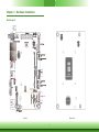
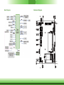
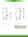
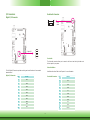
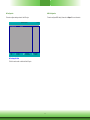
Chapter 2 - Hardware Installation
Board Layout
Top View
Bottom View

9
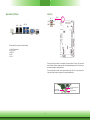
System CPU
The system board is equipped with a Kabylake-U microprocessor in socket BGA compatible
package 1356.
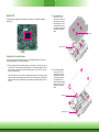
Installing the Thermal Solution
The CPU must be kept cool by using a heat sink or a heat spreader. Otherwise, the CPU will
overheat damaging both the CPU and system board.
1. Before you install the heat sink/heat spreader, you must apply a thermal paste onto the
top of the CPU. The thermal paste is usually supplied. Do not spread the paste all over the
surface. When you later place the heat sink/heat spreader on top of the CPU, the com-
pound will disperse evenly.
Some heat sinks come with a patch of pre-applied thermal paste. Do not apply thermal
paste if the heat sink/heat spreader already has a patch of thermal paste on its underside.
Peel the strip that covers the paste before you place the heat sink/heat spreader on top of
the CPU.
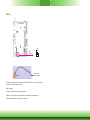
2A. Place the heat sink on
top of the CPU. The 4
push-pins on the heat sink
must match the 4 mount-
ing holes around the CPU
on the system board. Use
the push-pins to fasten the
heat sink on the system
board.
Mounting hole
Push-pin
2B. Place the heat spreader
on top of the CPU. The
4 standoffs of the heat
spreader must match the
4 mounting holes around
the system board. Use
the standoffs and supplied
screws to fasten the heat
spreader on the system
board.
Mounting hole
Standoff

10
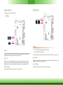
Block Diagram
Mechanical Diagram

11
System Memory
Important:
Electrostatic discharge (ESD) can damage your board, processor, disk drives, add-in
boards, and other components. Perform installation procedures at an ESD workstation
only. If such a station is not available, you can provide some ESD protection by wear-
ing an antistatic wrist strap and attaching it to a metal part of the system chassis. If
a wrist strap is unavailable, establish and maintain contact with the system chassis
throughout any procedures requiring ESD protection.
Important:
When the Standby Power LED is red, it indicates that there is power on the system
board. Power-off the PC then unplug the power cord prior to installing any devices.
Failure to do so will cause severe damage to the motherboard and components.
• One 260-pin SODIMM up to 16GB
• Single Channel DDR4 1866/2133MHz
Features
DDR4
Standby
Power
LED
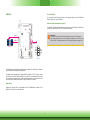
Installing the DIMM Module
1. Make sure the PC and all other peripheral devices connected to it has been powered down.
2. Disconnect all power cords and cables.
3. Locate the SODIMM socket on the system board.
4. Note the key on the socket. The key ensures the module can be plugged into the socket in
only one direction.
Note:
The system board used in the following illustrations may not resemble the actual
board. These illustrations are for reference only.

12
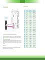
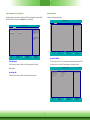
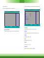
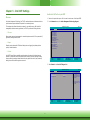
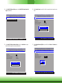
Jumper Settings
Clear CMOS Data
If you encounter the following conditions, you can reconfigure the system with the default val-
ues stored in the ROM BIOS.
a) CMOS data becomes corrupted.
b) You forgot the supervisor or user password.
To load the default values stored in the ROM BIOS, please follow the steps below:
1. Power-off the system and unplug the power cord.
2. Set JP1 pins 2 and 3 to On. Wait for a few seconds and set JP1 back to its default setting,
pins 1 and 2 On.
3. Now plug the power cord and power-on the system.
2-3 On:
Clear CMOS Data
1-2 On:
Normal (default)
31
2
31
2
JP1
6. Push down the module until the clips at each end of the socket lock into position. You will
hear a distinctive “click”, indicating the module is correctly locked into position.
Clip
5. Grasping the module by its edges, align the module into the socket at an approximately 30
degrees angle. Apply firm even pressure to each end of the module until it slips down into
the socket. The contact fingers on the edge of the module will almost completely disappear
inside the socket.
Clip

13
Chapter 2
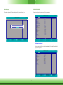
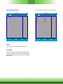
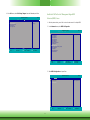
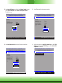
Auto Power-on Select
1-2 On:
Power-on via power button
(default)
2-3 On:
Power-on via AC power
JP16 is used to select the method of powering on the system. If you want the system to
power-on whenever AC power comes in, set JP16 pins 2 and 3 to On. If you want to use the
power button, set pins 1 and 2 to On.
When using the JP16 “Power On” feature to power the system back on after a power failure
occurs, the system may not power on if the power lost is resumed within 5 seconds (power
flicker).
JP16
3
1
2
3
1
2
JP12 is used to select the power level of backlight brightness control: +3.3V or +5V.
Backlight Brightness Select
2-3 On: +5V
1-2 On: +3.3V
(default)
Important:
Before powering-on the system, make sure that the power settings of JP12 match the
power specification of backlight control. Selecting the incorrect voltage will seriously
damage the backlight.
JP12
31
2
3
1
2

14
2
4
6
5
1
3
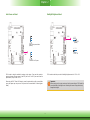
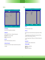
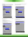
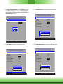
M.2 Signal Select
JP7 is used to select the M.2 signal: PCIe or SATA (default).
1-2 On: SATA
(default)
2-3 On: PCIe
JP7
3
1
2
3
1
2
Panel Power Select
JP13
1-2 On: +12V
3-4 On: +5V
5-6 On: +3.3V
(default)
JP13 is used to select the power supplied with the LCD panel.
Important:
Before powering-on the system, make sure that the power settings of JP13 match
the LCD panel’s specification. Selecting the incorrect voltage will seriously damage the
LCD panel.
5
1
3
2
4
6
5
1
3
2
4
6

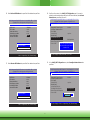
15
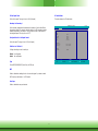
Rear Panel I/O Ports
The rear panel I/O ports consist of the following:
• 1 12V DC-in connector
• 2 GbE (RJ-45)
• 4 USB 3.0
• 1 VGA
• 1 DP++
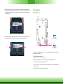
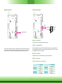
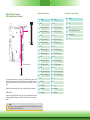
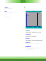
12V DC-in
DC-in
DC-in
LAN 1 LAN 2
USB 3.0
DP++
VGA
4 3
GND2 GND1
12V4
12V3
This 4-pin right angle connector is considered a low power solution. Connect a DC power cord
to this connector. Using a voltage more than the recommended range may fail to boot the sys-
tem or cause damage to the system board.
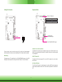
The 4-pin right-angle connector on the system board co-lays with a DC-in jack (optional) or
4-pin vertical type connector (optional) as the photo displayed below.
DC-in Jack (optional)
4-pin Vertical Type Connector
(optional)
4-pin Right Angle
Connector (default)
2 1

16
Graphics Interfaces
The display ports consist of the following:
• 1 VGA port
• 1 DP++ port
VGA Port
The VGA port is used for connecting a VGA monitor. Connect the monitor’s 15-pin D-shell cable
connector to the VGA port. After you plug the monitor’s cable connector into the VGA port,
gently tighten the cable screws to hold the connector in place.
DP++ Port
The DP++ port is a digital display interface used to connect a display device such as a com-
puter monitor. It is used to transmit audio and video simultaneously. The interface, which is
developed by VESA, delivers higher performance features than any other digital interfaces.
Driver Installation
Install the graphics driver. Refer to Chapter 4 for more information.
RJ45 LAN Ports
Features
• 1 Intel
®
I210AT PCI Express Gigabit Ethernet controller
• 1 Intel
®
I219LM PCIe with iAMT11.6
The LAN ports allow the system board to connect to a local area network with a network hub.
BIOS Setting
Configure the onboard LAN in the Advanced menu (the “ACPI Configuration” submenu) of the
BIOS. Refer to Chapter 3 for more information.
Driver Installation
Install the LAN drivers. Refer to Chapter 4 for more information.
LAN 2
LAN 1
VGA
DP++
LAN 1
LAN 2

17
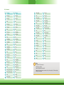
USB Ports
The USB device allows data exchange between your computer and a wide range of simultane-
ously accessible external plug and play peripherals.
The system board is equipped with 4 onboard USB 3.0 port (USB 1-2/3-4). The 10-pin connec-
tor allows you to connect 2 additional USB 2.0 ports (USB 6-7). The additional USB ports may
be mounted on a card-edge bracket. Install the card-edge bracket to an available slot at the
rear of the system chassis and then insert the USB port cables to a connector.
BIOS Setting
Configure the onboard USB in the Advanced menu (“USB Configuration” submenu) of the
BIOS. Refer to Chapter 3 for more information.
Driver Installation
You may need to install the proper drivers in your operating system to use the USB device.
Refer to Chapter 4 for more information.
Wake-On-USB Keyboard/Mouse (optional)
The Wake-On-USB Keyboard/Mouse function allows you to use a USB keyboard or USB mouse
to wake up a system from the S3 (STR - Suspend To RAM) state.
USB 1-2
USB 3.0
USB 3-4
USB 6-7
10
VCC
-Data0
+Data0
GND
VCC
-Data1
+Data1
GND
N.C.
12
USB 2.0
Important:
If you are using the Wake-On-USB Keyboard/Mouse function for 2 USB ports, the
+5V_standby power source of your power supply must support ≥1.5A. For 3 or more
USB ports, the +5V_standby power source of your power supply must support ≥2A.

18
I/O Connectors
Digital I/O Connector
The 8-bit Digital I/O connector provides monitoring and control functions to the connected
external devices.
Digital I/O Connector
Pins Function
1
DIO7
2
DIO6
3
DIO5
4
DIO4
5
DIO3
6
DIO2
7
DIO1
8
DIO0
9
5VSB
10
GND
Front Audio Connector
Front
Audio
1
2
10
9
Front Audio
The front audio connector allows you to connect to the line-out and mic-in jacks that are at
the front panel of your system.
Driver Installation
Install the audio driver. Refer to the Chapter 4 for more information.
Digital I/O
10
9
2
1
Front Audio Connector
Pins Function
1
Mic-L
2
GND
3
Mic-R
4
NC
5
Line-R
6
Mic-JD
7
GND
8
NC
9
Line-L
10
Line-JD

19
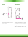
COM (Serial) Ports
COM 1 and COM 2 can be selected among RS232, RS422 and RS485.
The serial ports are asynchronous communication ports with 16C550A-compatible UARTs that
can be used with modems, serial printers, remote display terminals, and other serial devices.
Connecting External Serial Ports
The COM ports may be mounted on a card-edge bracket. Install the card-edge bracket to an
available slot at the rear of the system chassis then insert the serial port cable to the COM
connector. Make sure the colored stripe on the ribbon cable is aligned with pin 1 of the COM
connector.
BIOS Setting
Configure the serial COM ports in the Advanced menu (“SIO NUVOTON6101D” submenu) of
the BIOS. Refer to Chapter 3 for more information.
2
1
19
COM 1/COM 2:
RS232/422/485
COM 1 COM 2
20
Pin RS232 RS422 RS485
1
DCD_1 TX(B)_1 RX(B)/TX(B)_1
2
DSR_1 NC NC
3
SIN_1 TX(A)_1 RX(A)/TX(A)_1
4
RTS_1 NC NC
5
SO_1 RX(A)_1 NC
6
CTS_1 NC NC
7
DTR_1 RX(B)_1 NC
8
RI_1 NC NC
9
GND GND GND
10
GND GND GND
11
DCD_2 TX(B)_2 RX(B)/TX(B)_2
12
DSR_2 NC NC
13
SIN_2 TX(A)_2 RX(A)/TX(A)_2
14
RTS_2 NC NC
15
SO_2 RX(A)_2 NC
16
CTS_2 NC NC
17
DTR_2 RX(B)_2 NC
18
RI_2 NC NC
19
GND GND GND
20
GND GND GND
COM Port Connector

20
Front Panel Connector
HDD-LED - Hard Drive LED
This LED will be lit when the hard drive is being accessed.
PWR-LED - Power/Standby LED
When the system’s power is on, this LED will be lit. When the system is in the S1 (POS - Pow-
er On Suspend) state, it will blink every second. When the system is in the S3 (STR - Suspend
To RAM) state, it will blink every 4 seconds.
RESET-BTN - Reset Button
This button allows you to reboot without having to power off the system.
PWR-BTN - Power Button
This button is used to power on or off the system.
Front
Panel
Pin Pin Assignment Pin Pin Assignment
HDD-LED
6 HD_LED
PWR-BTN
1 Power Button
2 LED Power 3 Ground
RESET-BTN
3 Ground
PWR-LED
2 LED Power
5 Reset Button 4
SUS_LED
HDD-LED
PWR-LED
RESET-BTN
PWR-BTN
12
5
6
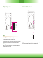
Standby Power LED
This LED will lit red when the system is in the standby mode. It indicates that there is power
on the system board. Power-off the PC and then unplug the power cord prior to installing any
devices. Failure to do so will cause severe damage to the motherboard and components.
Standby Power LED
Page is loading ...
Page is loading ...
Page is loading ...
Page is loading ...
Page is loading ...
Page is loading ...
Page is loading ...
Page is loading ...
Page is loading ...
Page is loading ...
Page is loading ...
Page is loading ...
Page is loading ...
Page is loading ...
Page is loading ...
Page is loading ...
Page is loading ...
Page is loading ...
Page is loading ...
Page is loading ...
Page is loading ...
Page is loading ...
Page is loading ...
Page is loading ...
Page is loading ...
Page is loading ...
Page is loading ...
Page is loading ...
Page is loading ...
Page is loading ...
Page is loading ...
Page is loading ...
Page is loading ...
Page is loading ...
Page is loading ...
Page is loading ...
Page is loading ...
Page is loading ...
Page is loading ...
Page is loading ...
Page is loading ...
Page is loading ...
Page is loading ...
Page is loading ...
Page is loading ...
Page is loading ...
-
 1
1
-
 2
2
-
 3
3
-
 4
4
-
 5
5
-
 6
6
-
 7
7
-
 8
8
-
 9
9
-
 10
10
-
 11
11
-
 12
12
-
 13
13
-
 14
14
-
 15
15
-
 16
16
-
 17
17
-
 18
18
-
 19
19
-
 20
20
-
 21
21
-
 22
22
-
 23
23
-
 24
24
-
 25
25
-
 26
26
-
 27
27
-
 28
28
-
 29
29
-
 30
30
-
 31
31
-
 32
32
-
 33
33
-
 34
34
-
 35
35
-
 36
36
-
 37
37
-
 38
38
-
 39
39
-
 40
40
-
 41
41
-
 42
42
-
 43
43
-
 44
44
-
 45
45
-
 46
46
-
 47
47
-
 48
48
-
 49
49
-
 50
50
-
 51
51
-
 52
52
-
 53
53
-
 54
54
-
 55
55
-
 56
56
-
 57
57
-
 58
58
-
 59
59
-
 60
60
-
 61
61
-
 62
62
-
 63
63
-
 64
64
-
 65
65
-
 66
66


Ask a question and I''ll find the answer in the document
Finding information in a document is now easier with AI
Related papers
Other documents
-
Lindy 39432 User manual
-
DeLOCK 89129 Datasheet
-
Dell Precision M4500 Owner's manual
-
Dell OptiPlex 980 User guide
-
Acer H274HL User guide
-
HP Z210 Small Form Factor Workstation Configuration Guide
-
Haier HL22FO1 User manual
-
DeLOCK 89125 Datasheet
-
Lenovo ThinkCentre M90p Configuration manual
-
Eurotech CPU-521-17 Owner's manual