Dell PE-R610-H211 Datasheet

Category
Servers
Type
Datasheet

This manual is also suitable for

DELL
POWEREDGE
R610
TECHNICAL GUIDEBOOK
INSIDE THE POWEREDGE R610
Dell™ PowerEdge™ R710 Technical Guidebook
SECTION 1. SYSTEM OVERVIEW 7
A. Overview / Description 7
A. Product Features Summary 7
SECTION 2. MECHANICAL 8
A. Chassis Description 8
B. Dimensions and Weight 8
C. Front Panel View and Features 8
D. Back Panel View and Features 9
E. Power Supply Indicators 9
F. NIC Indicators 9
G. Side Views and Features 10
H. Rails and Cable Management 10
Rails 10
CMAs 10
I. Fans 11
J. Control Panel / LCD 11
K. Security 12
I. Cover Latch 12
II. Bezel 12
III. Hard Drive 12
IV. TPM 12
V. Power Off Security 12
VI. Intrusion Alert 12
VII. Secure Mode 12
L. USB Key 13
M. Battery 13
N. Field Replaceable Units (FRU) 13
SECTION 3. ELECTRICAL 13
A. Volatility 13
B. ePPID (Electronic Piece Part Identication) 13
SECTION 4. POWER, THERMAL, ACOUSTIC 14
A. Power Efciencies 14
B. Power Supplies 14
I. Main Power Supply 14
C. Power Supply Specications 15
D. Environmental Specications 15
E. Power Consumption Testing 16
F. Maximum Input Amps 16
G. EnergySMART Enablement 17
H. Acoustics 17
TABLE OF CONTENTS
Dell™ PowerEdge™ R710 Technical Guidebook
SECTION 5. BLOCK DIAGRAM 19
SECTION 6. PROCESSORS 21
A. Overview / Description 21
B. Features 21
C. Supported Processors 22
D. Processor Congurations 22
Single CPU Conguration 22
CPU Power Voltage Regulation Modules (EVRD 11.1) 23
SECTION 7. MEMORY 23
A. Overview / Description 23
B. DIMMs Supported 24
C. Speed 25
D. Supported Congurations 28
E. Slots / Risers 29
F. Mirroring 29
G. Advanced ECC (Lockstep) Mode 29
H. Optimizer (Independent Channel) Mode 30
SECTION 8. CHIPSET 30
A. Overview / Description 30
Intel 5220 Chipset (cade named Tylersburg) I/O Hub (IOH) 30
IOH QuickPath Interconnect (QPI) 30
Intel Direct Media Interface 31
PCI Express Generation 2 31
Intel I/O Controller Hub 9 (ICH9) 31
SECTION 9. BIOS 31
A. Overview / Description 31
B. Supported ACPI States 32
C. I C (Inter-Integrated Circuit) 33
SECTION 10. EMBEDDED NICS / LAN ON MOTHERBOARD (LOM) 33
A. Overview / Description 33
SECTION 11. I/O SLOTS 33
A. Overview / Description 33
B. Boot Order 36
SECTION 12. STORAGE 36
A. Overview / Description 36
I. 2.5” SAS BACKPLANE SUBSYSTEM 36
II. Cabling 36
2
Dell™ PowerEdge™ R710 Technical Guidebook
B. Drives 36
I. Internal Hard Disk Drives 37
I. Hard Disk Drive Carriers 37
II. Empty Drive Bays 37
III. Diskless Conguration Support 37
IV. Hard Drive LED Indicators 37
C. RAID Congurations 38
D. Storage Controllers 40
I. SAS 6/iR 40
II. PERC 6i 40
E. LED Indicators 41
F. Optical Drives 41
G. Tape Drives 41
SECTION 13. VIDEO 41
A. Overview / Description 41
SECTION 14. AUDIO 41
A. Overview / Description 41
SECTION 15. RACK INFORMATION 42
A. Overview / Description 42
B. Cable Management Arm (CMA) 42
C. Rails 43
SECTION 16. OPERATING SYSTEMS 43
A. Overview / Description 43
B. Operating Systems Supported 43
Windows Support 43
Linux Supported 45
SECTION 17. VIRTUALIZATION 45
A. Operating Systems Supported 45
SECTION 18. SYSTEMS MANAGEMENT 45
A. Overview / Description 45
B. Server Management 46
Dell Systems Buil and Update Utility 46
OpenManage Srever Administrator 46
Management Console 46
Active Directory Snap-in Utility 46
Dell Systems Service Diagnostics Tools 46
eDocks 46
Dell Management Console DVD 46
Server Update Utility 46
Dell™ PowerEdge™ R710 Technical Guidebook
C. Embedded Server Management 46
I. Unmanaged Persistent Storage 47
II. Lifecycle Controller / Unied Server Congurator 47
III. iDRAC6 Express 47
IV. iDRAC6 Enterprise 48
SECTION 19. PERIPHERALS 50
A. USB peripherals 50
B. External Storage 50
SECTION 20. DOCUMENTATION 51
A. Overview, Description, and List 51
SECTION 21. PACKAGING OPTIONS 51
APPENDIX 52
Dell™ PowerEdge™ R610 Technical Guidebook
6
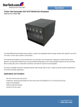
THE DELL™ POWEREDGE™ R610
Inspired by customer feedback, the Dell PowerEdge R610 server is engineered to simplify data
center operations, improve energy eciency, and lower total cost of ownership. System commonality,
purposeful design, and service options combine to deliver a rack server solution that can help you
better manage your enterprise.
Strong IT Foundation
The Dell PowerEdge R610 is a key building block for today’s data center. Designed for versatility and high performance,
it provides many of the virtualization, system management, and energy-eciency features you need now and the
scalability necessary to change as your business grows. This general-purpose Intel
®
-based 2-socket 1U server is ideal
for corporate data centers and remote sites that require a dense, highly available single- or dual-processor server at an
excellent value.
Enhanced Virtualization
Featuring Intel
®
Xeon
®
-based architecture, embedded hypervisors, expanded memory footprint, and I/O, the Dell
PowerEdge R610 delivers exceptional overall system performance and significant virtual machine-per-server capacity
versus the previous generation. With optional factory-integrated virtualization capabilities, you get tailored solutions –
built with the latest technologies from Dell and our trusted partners – which allow you to streamline deployment and
simplify virtual infrastructures. Choose your hypervisor from market leaders such as VMware
®
, Citrix
®
, and Microsoft
®
,
and enable virtualization with a few mouse clicks.
Energy-Optimized Technologies
Dell’s advanced thermal control helps optimize performance while minimizing system power consumption, ultimately
driving energy eciency across our latest core data center servers. These enhancements, over previous generations,
include ecient power supply units right-sized for system requirements, improved system-level design eciency,
policy-driven power and thermal management, and highly ecient standards-based Energy Smart components. Dell's
advanced thermal control is designed to deliver optimal performance at minimum system and fan power consumption
resulting in our quietest mainstream 1U servers to date.
Purposeful Design
The R610 takes advantage of Dell’s system commonality. Once your IT managers learn one system, they understand
how to manage next-generation Dell servers. Logical component layout and power supply placement also provide a
straightforward installation and redeployment experience.
Simplified Systems Management
Gain more control with the next-generation Dell OpenManage™ suite of management tools. These tools provide ecient
operations and standards-based commands designed to integrate with existing systems.
Dell Management Console (DMC) helps simplify operations and create stability by shrinking infrastructure management
to one console. This console delivers a single view and a common data source into the entire infrastructure management.
Built on Symantec
®
Management Platform, it has an easily extensible, modular foundation that can provide basic hardware
management all the way up to more advanced functions such as asset and security management. DMC is designed to
reduce or eliminate manual processes enabling you to save time and money for more strategic technology usage.
Secure, ecient, and more user friendly than its predecessors, the Dell Unified Server Configurator (USC) delivers “Instant On”
integrated manageability through a single access point. You get quick, persistent access to the tool because it is embedded
and integrated into the system for increased flexibility and capabilities. The USC is a one-stop shop for deploying operating
systems with built-in driver installations, firmware updates, hardware configuration, and issue diagnoses.
Dell™ PowerEdge™ R610 Technical Guidebook
7
FEATURE DETAILS
Processor
Nehalem EP
Front Side Bus
Intel QuickPath Interconnect (QPI) @ maximum 6.GT/s
# Procs
2S
# Cores
4 cores
L2/L3 Cache
4MB and 8MB
Chipset
Tylersberg
DIMMs
RDIMM or UDIMM DDR3 (12 DIMMs – 6 per processor)
Min/Max RAM
1GB – 96GB
HD Bays
Internal hard drive bay and hot-plug backplane
Up to six 2.5" SAS, SATA or SSD Drives
HD Types
SAS, SATA, Near-line SAS, and SSD
Ext Drive Bay(s)
External USB oppy.
Optional SATA half-height optical drives such as DVD-ROM or DVD+RW.
Int. HD Controller
PERC 6i and SAS 6/iR
Optional HD Controller
PERC 5/E and PERC 6/E
BIOS
4MB ash for system BIOS, SAS, and Video BIOS
Video
Integrated Matrox G200, 8MB shared video memory
Availability
HP hard drives, HP power; memory SDDC, ECC, control line parity, optional
redundant cooling.
Server Management
Dell Embedded Server Management provides IPMI 2.0 compliance.
I/O Slots
Two x8 Gen2 slots
RAID
PERC 6i utilizing battery backed 256MB DDRII 667
NIC/LOM
Broadcom 5809C (2 cards/4ports)
USB
Five USB ports (2 front, 2 rear, 1 internal)
Power Supplies
Two hot-plug high-efcient 502W PSU (Energy Smart)
Two hot-plug 717W PSUs (High Output)
Front Control Panel
The system control panel is located on the front of the system chassis to
provide user access to buttons, display, and I/O interfaces.
System ID
Front and Rear (0x0235)
Fans
Six
Single processor congurations will only have ve fans
Chassis
1U rackmount
SECTION 1. SYSTEM OVERVIEW
A. Overview / Description
The PowerEdge R610 will lead Dell's 11th Generation PowerEdge portfolio in key areas of dierentiation,
primarily:
•Virtualization,
•Power,thermal,eciency
•Systemsmanagement,andusability
B. Product Features Summary
Dell™ PowerEdge™ R610 Technical Guidebook
8
SECTION 2. MECHANICAL
A. Chassis Description
The PowerEdge R610 is a 1U rackmount chassis. The updated design includes a new LCD, bezel and
hard-drive carriers. Additional changes include tool-less rack latches, a pull out tray for customer labels,
and LOM0/iDRAC MAC address; labels; support persistent storage (internal USB and SD card slots and
external SD card slots); updated power supplies and removal process.
B. Dimensions and Weight
Height 4.26cm (1.68”)
Width 48.24cm (18.99” – includes rack latches)
Depth 77.2cm (30.39” – includes bezel and power supply handles)
Weight (maximum config) 17.69kg (39lbs)
.
C. Front Panel View and Features
Front I/O panel access including USB and VGA interfaces. The following components are located on
the front:
•SystemIdenticationpanel(Informationtag).Aslide-outpanelforsystemidenticationlabels
including the Express Service tag, embedded NIC MAC address and iDRAC6 Enterprise card
MAC address. Space has been provided for an additional label.
•Poweronindicator,powerbutton
•NMIindicator(Nonmaskableinterrupt).AdevicesendsanNMItosignaltheprocessorabout
hardware errors. It is used to troubleshoot software and device driver errors when using certain
operating system
•(2)USBconnectors.ConnectsUSBdevicestothesystem.TheportsareUSB2.0compliant
•Videoconnector
•LCDmenubuttons.AllowsyoutonavigatethecontrolpanelLCDmenu
•LCDpanel.ProvidessystemID,statusinformation,andsystemerrormessages
•Systemidenticationbutton
•Opticaldrive(optional)
•Harddrives
Dell™ PowerEdge™ R610 Technical Guidebook
9
D. Back Panel View and Features
The following components are located on the rear panel of the PowerEdge R610 enclosure:
•(1)15-pinVGAconnector
•(1)9-pinserialportconnector
•(4)Integrated10/100/1000EthernetRJ-45connectors
•(1)RearsystemIDbutton
•(1)ActiveIDCableManagementArmexternalLEDjack
•(2)USBports
•(1)(Optional)iDRAC6EnterpriseRJ-45port
•(1)(Optional)iDRAC6ExpressVFlashmediaslot
•(2)PCIeslots
E. Power Supply Indicators
The PSUs on the PowerEdge R610 have one status bi-color LED: green for AC power present and
amber for a fault.
F. NIC Indicators
LED POWER SUPPLY STATUS
AC power is not present
AC power is present
Fault of any kind is detected
DC power is applied to the system
PSU mismatch (when hot-added/swapped)
INDICATOR INDICATOR CODE
Link and activity indicators are off
The NIC is not connected to the network
Link indicator is green
The NIC is connected to a valid network link at 1000 Mbps
Link indicator is amber
The NIC is connected to a valid network link at 1000 Mbps
Activity indicator is green blinking
Network data is being sent or received
Dell™ PowerEdge™ R610 Technical Guidebook
10
G. Side Views and Features
Rack installation components such as rails are provided with the PowerEdge R610 Rack Kit. The rack
installation components are as follows: sliding rack mount with latest generation Cable Management
Arm (CMA). The PowerEdge R610 will feature slam latches to oer easier removal from the rack. When
the system is installed in a rack, please observe the following guideline:
When the system is installed in a rack, only Dell-approved CMAs should be installed behind the chassis.
Rails
•Enable the replacement of thumbscrews with slam latches on the chassis for easier stowing in
the rack.
•Include the new, simple, and intuitive ReadyRail™ tool-less rack interface for square-hole and
round-hole racks.
•Provide significantly improved compatibility with non-Dell racks.
•Static rails for the R610 & R710 fit in all types of four-post and two-post racks available in the
industry including four-post threaded hole racks.
CMAs
•Provide much larger vent pattern for improved airflow through the CMA.
•Include a common support tray for eliminating CMA sag.
•Replaced tie wraps with hook and loop straps to eliminate risk of cable damage during cycling.
•Maintain key feature of being fully reversible with no conversion required.
H. Rails and Cable Management
Dell™ PowerEdge™ R610 Technical Guidebook
11
I. Fans
Six dual-rotor 40mm fans are mounted in a fan assembly that is located in the chassis between the
hard drive bay and the processors. Only five fans will be populated in systems with a single processor
configuration. Each fan has a connector that plugs directly into the planar. (The PowerEdge R610 fans
cannot be hot-swapped. There are six fan zones in the R610, with one zone for each system fan.)
System fan speed is pulse-width modulated. Redundant cooling is supported with only one rotor failing
at a time. The Embedded Server Management logic in the system will control and monitor the speed of
the fans. A fan failure or over-temperature in the system will result in a notification from iDRAC6.
The PowerEdge R610 Power Supply Units do not have any integrated fans; they are cooled by the
system fans in front of them. The system requires a PSU Close Out (metal cover) in place of the empty
power supply slot. To provide cooling when the system is o, both rotors in FAN_MOD1 will run o of
V
aux
power at a low speed setting when the ambient air temperature in the PSU passes a pre-defined
threshold. The iDRAC controls the fan in AutoCool mode.
J. Control Panel / LCD
The system control panel is located on the front of the system chassis to provide user access to buttons,
display, and I/O interfaces. Features of the system control panel include:
•ACPI-compliantpowerbuttonwithanintegratedgreenpowerLED(controlledbyiDRAC6)
•128x20pixelLCDpanelwithcontrols
•Twonavigationbuttons
•Oneselectbutton
•OnesystemIDbutton
•Non-MaskableInterrupt(NMI)button(recessed)
•Ambienttemperaturesensor
•TwoexternalUSB2.0connectors(withaninternalUSBconnectorandInternalSDModule)
•15-pinVGAconnector
The LCD panel is a graphics display controlled by iDRAC6, unlike the 9G panel which had its own CPLD.
Error codes can be sent to the display by either iDRAC6 or BIOS.
Dell™ PowerEdge™ R610 Technical Guidebook
12
The LCD panel is a graphics display controlled by the BMC/ESM. Both ESM and BIOS can send error
codes and messages to the display.
The system's LCD panel provides system information and status messages to signify when the system is
operating correctly or when the system needs attention.
The LCD backlight lights blue during normal operating conditions and lights amber to indicate an error
condition. When the system is in standby mode, the LCD backlight is o and can be turned on by
pressing the Select button on the LCD panel. The LCD backlight will remain o if the "No Message"
option is selected through the iDRAC6, the LCD panel, or other tools.
BIOS has the ability to enter a “Secure Mode” through Setup, which locks the power and NMI buttons.
When in this mode, pressing either button has no eect but does not mask other sources of NMI and
power control.
K. Security
I. Cover Latch
A tooled entry latch is provided on the top of the unit to secure the top cover to the chassis.
II. Bezel
A metal bezel is mounted to the chassis front to provide the Dell ID. A lock on the bezel is used to
protect un-authorized access to system peripherals and the control panel. System status via the LCD is
viewable even when the bezel is installed.
III. Hard Drive
The optional front bezel of the system contains a lock. A locked bezel secures the system hard drives.
IV. TPM
The TPM is used to generate/store keys, protect/authenticate passwords, and create/store digital
certificates. TPM can also be used to enable the BitLocker™ hard drive encryption feature in Windows
Server
®
2008. TPM is enabled through a BIOS option and uses HMAC-SHA1-160 for binding. There will be
dierent planar PWA part numbers to accommodate the dierent TPM solutions. The “Rest of World”
(ROW) version will have the TPM soldered onto the planar. The other version of the planar (post RTS
and primarily for use by China) will have a connector for a plug-in module.
V. Power O Security
The control panel is designed such that the power switch cannot be accidentally activated. The lock on
the bezel secures the switch behind the bezel. In addition, there is a setting in the CMOS setup that
disables the power button function.
VI. Intrusion Alert
A switch mounted on the left riser board is used to detect chassis intrusion. When the cover is opened,
the switch circuit closes to indicate intrusion to ESM. When enabled, the software can provide
notification to the customer that the cover has been opened.
VII. Secure Mode
BIOS has the ability to enter a secure boot mode via Setup. This mode includes the option to lock out
the power and NMI switches on the Control Panel or set up a system password. See the Whoville BIOS
Specification for details
Dell™ PowerEdge™ R610 Technical Guidebook
13
L. USB Key
The port on the control panel is for an optional USB key and is located inside the chassis. Some of the
possible applications of the USB key are:
•Usercustombootandpre-bootOSforeaseofdeploymentordisklessenvironments
•USBlicensekeysforsoftwareapplicationslikeeToken™orSentinelHardwareKeys
•
Storage of custom logs or scratch pad for portable user-defined information (not hot-swappable)
M. Battery
A replaceable coin cell CR2032 3V battery is mounted on the planar to provide backup power for the
Real-Time Clock and CMOS RAM on the ICH9.
N. Field Replaceable Units (FRU)
The planar contains a serial EEPROM to contain FRU information including Dell part number, part
revision level, and serial number. iDRAC6 Enterprise (previously referred to as Advanced Management
Enablement Adapter - AMEA) also contains a FRU EEPROM. The backplane’s SEP and the power
supplies’ microcontroller are also used to store FRU data.
SECTION 3. ELECTRICAL
A. Volatility
See Appendix A of this Technical Guidebook.
B. ePPID (Electronic Piece Part Identification)
ePPID is an electronic repository for information from the PPID label that is stored in non-volatile RAM.
The BIOS reports the ePPID information using SMBIOS data structures. ePPID includes the following
information:
•Dellpartnumber
•Partrevisionlevel
•Countryoforigin
•SupplierIDcode
•Datecode(dateofmanufacture)
•Uniquesequencenumber
COMPONENT DESCRIPTION STORAGE LOCATION
BOARDS
Planar
PWA,PLN,SV,DELL,R610 iDRAC FRU
2.5" Backplane
PWA,BKPLN,SV,R610,2.5SASX6 SEP
POWER SUPPLIES
717W High Output PSU
PWR SPLY,717W,RDNT,ASTEC PSU Microcontroller
PWR SPLY,717W,RDNT,DELTA PSU Microcontroller
502W Energy Smart PSU
PWR SPLY,502W,RDNT,ASTEC PSU Microcontroller
PWR SPLY,502W,RDNT,COLDWATT PSU Microcontroller
STORAGE CARDS
PERC 6/i Integrated
ASSY, CRD, PERC6I-INT, SAS, NOSLED FRU
PERC 6/E External
PWA, CTL, PCIE, SAS, PERC6/E,ADPT FRU
SAS 6/iR Integrated
PWA, CTL, SAS, SAS6/IR, INTG FRU
Table: ePPID Support list
Dell™ PowerEdge™ R610 Technical Guidebook
14
SECTION 4. POWER, THERMAL, ACOUSTIC
A. Power Eciencies
One of the main features of the 11th generation of PowerEdge servers is enhanced power eciency. The
R610 achieves higher power eciency by implementing the following features:
•User-selectablepowercap(subsystemswillthrottletomaintainthespeciedpowercap)
•Improvedpowerbudgeting
•Accurateinlettemperature
•PSU/VReciencyimprovements
•Switchingregulatorsinsteadoflinearregulators
•Closedloopthermalthrottling
•PWMfanswithanincreasednumberoffanzonesandconguration-dependentfanspeeds
•Increasedrearventing/3Dventing
•UseofDDR3memory(lowervoltagecomparedtoDDR2,UDIMMsupport)
•CPUVRdynamicphaseshedding
•MemoryVRstaticphaseshedding
•Randomtimeintervalforsystemstart
•Allowsanentireracktopoweronwithoutexceedingtheavailablepower
•BIOSPower/Performanceoptionspage
•ActivePowerController(BIOS-basedCPUP-statemanager)
•Abilitytopowerdownorthrottlememory
•AbilitytodisableaCPUcore
•AbilitytoturnoLOMsorPCIelaneswhennotbeingused
•OptiontorunPCIeatGen1speedsinsteadofGen2
B. Power Supplies
I. Main Power Supply
Thebaseredundantsystemconsistsoftwohot-swap502WEnergySmartpowersuppliesina1+1
configuration. A 717W high-output power supply is also available. The power supplies connect directly
to the planar. There is a power cable to connect between the planar and the backplane. The R610 power
supplies do not have embedded cooling fans; the PSUs are cooled only by the system cooling fans. The
three status LEDs on the PSU have been replaced with a single bi-color LED starting with the PT build.
Starting with the 11th generation of PowerEdge servers (R710, R610, T610, M610, and M710), the
power supplies no longer have a FRU EEPROM. FRU data is now stored in the memory of the PSU
Microcontroller. Additionally, the PSU Firmware can now be updated by the BMC over the PMBus.
Power is “soft-switched,” allowing power cycling via a switch on the front of the system enclosure, or
via software control (through server
management functions).
If using only one power supply, the single PSU should be installed in the PS1 bay and a PSU Close Out
(metal cover) will be installed in the PS2 bay. The use of the PS1 bay for the single PSU configuration is
done for consistency only – there is nothing that prevents the use of the PS2 bay in a single PSU
configuration.
Dell™ PowerEdge™ R610 Technical Guidebook
15
C. Power Supply Specifications
AC POWER SUPPLY (PER POWER SUPPLY)
Wattage
717 Watt (High Output)
570 Watt (Energy Smart)
Voltage
90-264 VAC, autoranging, 47-63Hz
Heat Dissipation
2446.5 BTU/hr maximum (High Output)
1712.9 BTU/hr maximum (Energy Smart)
Maximum Inrush Current
Under typical line conditions and over the entire system ambient
operating range, the inrush current may reach 55A per power supply
for 10ms or less.
D. Environmental Specifications
TEMPERATURE
Operating
10° to 35°C (50° to 95°F) with a maximum temperature gradation of
10°C per hour Note: For altitudes above 2950 feet, the maximum
operating temperature is de-rated 1°F/550 ft
Storage
-40° to 65°C (-40° to 149°F) with a maximum temperature gradation of
20°C per hour
RELATIVE HUMIDITY
Operating
20% to 80% (non-condensing) with a maximum humidity gradation of
10% per hour
Storage
5% to 95% (non-condensing) with a maximum humidity gradation of
10% per hour
Dell™ PowerEdge™ R610 Technical Guidebook
16
MAXIMUM VIBRATION
Operating
0.26 Grms at 5 – 350Hz for 5 minutes in operational orientations
Storage
1.54 Grms at 10 – 250Hz for 10 minutes in all orientations
MAXIMUM SHOCK
Operating
Half sine shock in all operational orientations of 31G 5% with a pulse
duration of 2.6 ms 10%
Storage
Half sine shock on all six sides of 71G 5% with a pulse duration of 2 ms
10% Square wave shock on all six sides of 27G with velocity change @
235 in/sec or greater
ALTITUDE
Operating
-16 to 3048 m (-50 to 10,000 ft) Note: For altitudes above 2950 feet, the
maximum operating temperature is de-rated 1°F/550 ft
Storage
-16 to 10,600 m (-50 to 35,000 ft)
E. Power Consumption Testing
FEATURE ENERGY SMART PSU HIGH OUTPUT PSU
Dimensions
L-249 mm
1
x W-65.5 mm x H-38.2 mm
Status Indicators
1 x bi-color Light Emitting Diode
Integrated Fans
None
Fixed Input Plug
IEC-C14
AC Cord Rating
15 Amps @ 120 VAC, 10 Amps @ 240 VAC
Input Voltage
90 – 264 VAC
Auto-ranging
Yes
Line Frequency
47 – 63 Hertz
Maximum Inrush Current
55 Amps per supply for 10 ms or less
Hot-Swap Capability
Yes
Output Power
502 Watts 717 Watts
Maximum Heat Dissipation
1712.9 BTU per hour 2446.5 BTU per hour
Efciency (20% - 100% Load)
86.5 - 90% @ 115 VAC
88 - 92% @ 230 VAC
85 – 88.5% @ 115 VAC
86.5 – 90.5% @ 230 VAC
F. Maximum Input Amps
Maxinputcurrent(HighOutput):10.5A@90VAC,5.3A@180VAC
Maxinputcurrent(EnergySmart):7.0A@90VAC,3.5A@180VAC
Dell™ PowerEdge™ R610 Technical Guidebook
17
G. EnergySMART Enablement
The 11G family implements aspects of Dell’s new Energy Smart strategy.
Majordierencesinclude:
•DiscontinuingEnergySmart-brandedserverswithlimitedcongurationsandinsteadoering
Energy Smart components on a portfolio level, such as high capacity and Energy Smart power
supplies
•Allowingcustomerstoordereitheralowestpowerfootprintcongurationorabest
performance-per-watt configuration
•OeringEnergySmartselectedcomponentssuchasDIMMsorharddrives,butnot“cherry
picking" or screening individual manufacturers' components based on energy consumption.
H. Acoustics
The acoustical design of the PowerEdge R610 reflects the following:
•AdherencetoDell’shighsound-qualitystandards.Soundqualityisdierentfromsoundpower
level and sound pressure level in that it describes how humans respond to annoyances in sound,
like whistles, hums, etc. One of the sound quality metrics in the Dell specification is prominence
ratio of a tone, and this is listed in the table below.
•Oceenvironmentacoustics.ComparethevaluesforLpAinthetablebelowandnotethat
they are lower than ambient noise levels of typical oce environments.
•Hardwarecongurationsaectsystemnoiselevels.Dell’sadvancedthermalcontrolprovides
for optimized cooling with varying hardware configurations. Most typical configurations will
perform as listed in the table below. However some less typical configurations and components
can result in higher noise levels, for example, a system configured with a PERC6/E card (noted
in table below). (Please note that dBA values are not additive.)
•Noiserampanddescentatbootup.
•Fanspeeds,hencenoiselevels,rampduringthebootprocessinordertoadda
layer of protection for component cooling in the case that the system were not to
boot properly.
•ThepowersuppliesarepassiveintheR610,thatis,theycontainnointernalfans.
After power is connected to the power supplies, initialization of power supply
communication with the servers fan control firmware takes place and assesses if
cooling is required in standby mode. It is therefore normal for chassis fan #1 to
operate at full speed for approximately 30 seconds after power is connected to
thesystem.Thefanwillrampdowntoafullstopafterthistimeperiodin<_25°C
ambient conditions.
Dell™ PowerEdge™ R610 Technical Guidebook
18
PowerEdge R610 with GY134 fans (quantity below), 2x 502-W KY091 Power Supplies, 2.40 GHz Quad-Core E5530
CPUs (quantity below), 2-GB DIMMs (quantity below), 1x DVD Drive, Perc 6i card, and 4x XK112 Hard Disk Drives
2x CPUs, 6x fans, 8x DIMMs
Condition in 23±2° C ambient
LwA-UL, bels LpA, dBA Tones
Standby
1.8 16 No prominent tones
Idle
5.3 35 No prominent tones
Active Hard Disk Drives
5.4 37 No prominent tones
Stressed Processor
5.3 35 No prominent tones
1x CPU, 5x fans, 4x DIMMs
Idle
5.2 34 No prominent tones
Active Hard Disk Drives
5.4 37 No prominent tones
Stressed Processor
5.2 34 No prominent tones
2x CPU plus a PERC6/E external
RAID controller
6.0 44 No prominent tones
Denitions
Standby: AC Power is connected to power supply units but system is not turned on.
Idle: Reference ISO7779 (1999) denition 3.1.7; system is running in its OS but no other specic activity.
Active Hard Drives: An operating mode per ISO7779 (1999) denition 3.1.6; Section C.9 of ECMA-74
9th ed. (2005) is followed in exercising the hard disk drives.
Stressed Processor: An operating mode per ISO7779 (1999) denition 3.1.6; SPECPower set to 50%
loading is used.
LwA-UL: The upper limit sound power level (LwA) calculated per section 4.4.2 of ISO 9296 (1988) and
measured in accordance with ISO7779 (1999).
LpA: The average bystander position A-weighted sound pressure level calculated per section 4.3 of
ISO9296 (1988) and measured in accordance with ISO7779 (1999). The system is placed in a rack with
its bottom at 25 cm from the oor.
Tones: Criteria of D.5 and D.8 of ECMA-74 9th ed. (2005) are followed to determine if discrete tones are
prominent. The system is placed in a rack with its bottom at 75 cm from the oor. The acoustic trans-
ducer is at front bystander position, ref ISO7779 (1999), Section 8.6.2.
Dell™ PowerEdge™ R610 Technical Guidebook
19
SECTION 5. BLOCK DIAGRAM
The PowerEdge R610 electrical system consists of the planar subsystem with TPM, iDRAC6 Enterprise,
iSCSI key, PCIe risers, power supply subsystem, system control panel, backplane, and storage (PERC 6/i
or SAS 6/iR) card. The features and functions of these electrical subsystems are detailed below.
The R610 motherboard is an internal Dell-designed board that contains the processor electronics,
memory, and most key processor functions on a single planar.
Dell™ PowerEdge™ R610 Technical Guidebook
20
1 2
3
4
5
6
7
8
9
10
11
12
13
14
15
1. Embedded Network Interface Ports (4)
2. iDRAC6 Enterprise (Optional)
3. Broadcom 5709c Network Interface controller
(second controller under PCI card)
4. PCIe Gen2 Riser / Slots
5. iDRAC6 Express / Lifecycle Controller
6. DIMM Slots
7. Heat Sink / Processor Socket
8. R610
9. Redundant fans
10. Hard drive bay
11. Internal SD Module
(Embedded Hypervisor Optional)
12. DIMM Slots
13. Heat Sink / Processor Socket
14. PCIe Gen2 Riser / Slots
15. Dual Redundant Power Supplies
  • Page 1 1
  • Page 2 2
  • Page 3 3
  • Page 4 4
  • Page 5 5
  • Page 6 6
  • Page 7 7
  • Page 8 8
  • Page 9 9
  • Page 10 10
  • Page 11 11
  • Page 12 12
  • Page 13 13
  • Page 14 14
  • Page 15 15
  • Page 16 16
  • Page 17 17
  • Page 18 18
  • Page 19 19
  • Page 20 20
  • Page 21 21
  • Page 22 22
  • Page 23 23
  • Page 24 24
  • Page 25 25
  • Page 26 26
  • Page 27 27
  • Page 28 28
  • Page 29 29
  • Page 30 30
  • Page 31 31
  • Page 32 32
  • Page 33 33
  • Page 34 34
  • Page 35 35
  • Page 36 36
  • Page 37 37
  • Page 38 38
  • Page 39 39
  • Page 40 40
  • Page 41 41
  • Page 42 42
  • Page 43 43
  • Page 44 44
  • Page 45 45
  • Page 46 46
  • Page 47 47
  • Page 48 48
  • Page 49 49
  • Page 50 50
  • Page 51 51
  • Page 52 52
  • Page 53 53
  • Page 54 54
  • Page 55 55
  • Page 56 56

Dell PE-R610-H211 Datasheet

Category
Servers
Type
Datasheet
This manual is also suitable for

Ask a question and I''ll find the answer in the document

Finding information in a document is now easier with AI