
Polk Audio
5601 Metro Drive
Baltimore, Maryland 21215
(800) 377-7655
RM6504-1

OWNER’S
MANUAL
RM6500SYSTEM
RM2300
SATELLITES
RM2600
CENTER CHANNEL
Page is loading ...

GETTING STARTED
The RM6500 carton should contain the following items:
"
Four (4) magnetically shielded satellite speakers
" One (1) magnetically shielded center channel speaker
"
One (1) powered subwoofer
"
Four (4) wall mount brackets for the front and surround satellites and four screws to install them on the speaker
The RM2300 carton should contain the following items:
"
Two (2) magnetically shielded satellite speakers
"
Two (2) wall mount brackets for the front and surround satellites and four screws to install them on the speaker
The RM2600 carton should contain the following items:
" One (1) magnetically shielded center channel speaker
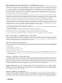
SPEAKER PLACEMENT
CENTER CHANNEL SPEAKER (Figures A & B)
Place the center speaker as close to the TV as possible. The most popular placement is right on top of your TV set. It is also fine to place it
below the TV or on the wall directly above the TV (using optional wall bracket such as one from OmniMount
®
).
FRONT SATELLITES (Figures A & B)
Place the front satellites about as far apart as you are sitting from them. Avoid placing them less than 2 feet from side walls. When mounting
the speakers on stands or on a shelf, place them at or near your ear level. If you choose to wall mount them above ear level, the included wall
bracket will angle the speaker downward. Orienting the bracket sideways on the satellite will point it slightly inward (Figures E & F).
SURROUND SPEAKERS (Figures A & C)
The best placement for surround channel speakers is high on the side walls, facing each other and slightly behind your listening position. If this place-
ment is not possible, the speakers may be placed on the rear wall. In either case, mount the speakers two to four feet above the seated listener’s head.
SUBWOOFER (Figures A,B,C & D)
The subwoofer may be placed in an entertainment center, behind furniture or next to a sofa or chair. The subwoofer may be placed anywhere
in the room but you will get the best performance when it is on the same side of the room as the front satellites and near a wall or corner. It
may lie on its side, but placing it on its feet gives the best performance. NEVER LAY THE SUBWOOFER ON THE AMPLIFIER END— THIS WILL
DAMAGE THE AMPLIFIER. The RM subwoofer is not magnetically shielded and should not be placed close to a television set.
If you see any color distortion in your TV, move the subwoofer away from the set.
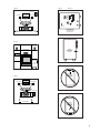
WALL MOUNTING THE SATELLITES (Figures E & F)
The satellite speakers are supplied with wall mounting brackets. Follow the steps below to safely secure the brackets and speakers.
On-wall installation of RM satellites requires basic skills in using tools such as a drill and screwdriver. If you are in doubt that you
possess the necessary skills or tools, consult your Polk dealer or a professional installer.
"
Make sure the locations you select do not conceal electrical wiring or plumbing.
"
Hold the speaker in the chosen location to make sure it clears the ceiling, adjacent walls, corners, beams, lighting fixtures and door/window
frames.
"
Attach the bracket to the satellite with the supplied screw as shown. The angle of the bracket allows you to point the speaker toward your
listening position. Turn the bracket to get the angle you want and tighten the screw. Be sure the 2 tabs on the bracket engage the 2
depressions on the satellite.
"
If you are certain that there is a stud behind the wall surface, drive #10 panhead screws (not supplied) through the wall and into the stud
leaving screw heads protruding 1/4".
"
If there is no stud behind the chosen location, install #10 wall anchors (not supplied) into the wall by following wall anchor manufacturer’s
instructions, leaving screw heads protruding 1/4". Always use two wall anchors and screws per speaker.
"
Line up speaker so that screw heads pass through the large center holes of the keyhole slots. Let speaker slide straight down, allowing screw
heads to slip behind the smaller end of the keyhole slots.
"
If the supplied wall mount brackets do not allow the mounting angle which meets your needs, or if you wish to ceiling mount the satellites,
use optional, fully articulating “ball and socket” type mounting brackets, such as those made by OmniMount.
®
CENTER CHANNEL WALL OR CEILING MOUNTING
Use an optional, fully articulating “ball and socket” type mounting bracket, such as those made by OmniMount
®
. Follow the manufacturers
instructions for installation.
ENGLISH 1

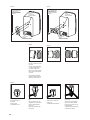
CONNECTING THE SPEAKERS TO THE SYSTEM (Figures G,H & I)
Use two conductor 16 gauge or thicker audiophile grade speaker wires. Measure enough wire to reach from your receiver or amp to each speaker plus
an additional 12" to allow moving the speakers or receiver without having to disconnect the wires. One of the terminals on the rear of the speaker is
marked red (+) and the other black (-). Make certain that you connect the wire from the red (+) terminal of your amplifier to the red (+) terminal on
your speaker, and the wire from the black (-) terminal of the amplifier to the black (-) terminal on your speaker. Most wire has some indication (such
as color code, ribbing, or writing) on one of the two conductors to help maintain consistency. If your speakers sound “thin” with little bass and little
to no center image, the chances are that one of the speaker wires is connected backwards. Double check all connections.
This system features a powered subwoofer that has a built-in low pass filter to separate the bass from the full range signal. Some receivers also con-
tain filters that may interfere with sound quality when coupled with the filters in a powered subwoofer. For this reason, it is not advisable to use
the “subwoofer output” on your receiver. For best performance, and to assure that there is no filter redundancy, we recommend the connection
method illustrated in Fig. H.
If your receiver has a “full range” subwoofer output, you may choose to run an RCA cable from this output to the low level line input of your sub-
woofer. Before using this option, make certain that your receiver’s subwoofer output is truly “full range,” otherwise the combination of filters will
cancel each other out, thus interfering with sound quality. Refer to your equipment manual, or consult your dealer before choosing this option.
Speaker level inputs recommended in Fig. H will generally provide better performance.
PREFERRED SUBWOOFER CONNECTION METHOD
"
Connect the left and right front speaker outputs of your receiver or amplifier to the SPEAKER LEVEL INPUTS of the powered subwoofer.
"
Connect the satellite speakers to the SPEAKER LEVEL OUTPUTS of the subwoofer (Fig. H).
"
If it is more convenient, parallel wire the subwoofer and satellites (Fig. I) from your amplifier.
"
Connect the center channel speaker directly to the center speaker output of your receiver or amplifier.
"
Connect the surround satellites directly to the rear or surround channel outputs of your receiver or amplifier.
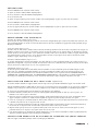
ADJUSTING THE POWERED SUBWOOFER
The subwoofer has been optimized to blend perfectly with the satellites of your RM system. A bass volume control allows you to adjust the level
of the subwoofer to suit the acoustics of your room and your personal taste. Adjust by ear using a wide variety of program material. The power
switch is marked “off” and “auto on.” It will sense a signal and turn on when set to “auto on” position which is recommended for normal use.
Turn to “off” if the system will not be used for extended periods of time, such as a vacation.
RECEIVER SET UP
All surround sound receivers allow you to match the electronics to your speakers. Refer to the owners manual of your receiver or surround
processor to learn how this is done. To get the best performance from the RM6500, use the following settings:
"
Front Speakers - Set to “Large”
"
Center Speaker - Set to “Normal” or “Small”
"
Surround Speakers - Set to “Small”
"
Subwoofer - Set to “Off” or “None.” This setting may not make sense to you as your RM6500 system has a subwoofer, but trust us, this is the
right setting. Select the “Subwoofer-On” setting only if you are using the alternate subwoofer connection described above.
SAFE LIMITS OF OPERATION
Your Polk loudspeakers are made with the highest quality materials for years of trouble-free performance. However, damage to loudspeakers can
occur when an amplifier, regardless of its wattage, is made to play at higher listening levels than its power can clearly produce (usually beyond
the “1 to 2 O’clock” position on the volume control).
This results in very high levels of audible distortion, originating in the amplifier, which adds a harsh, gritty sound to the music. Contrary to
popular belief, a speaker is more likely to be damaged by trying to get too much volume from a low-powered amp or receiver than from a
high-powered one.
MAINTAINING THE APPEARANCE OF RM SERIES SPEAKERS
Your new speaker cabinet is made of a rugged material that can be dusted or cleaned with a moist cloth. Avoid harsh detergents and cleaning
fluids; they can permanently damage your speakers’ finish. Gently vacuum the grilles to remove dust.
TECHNICAL ASSISTANCE OR SERVICE
If, after following the hook-up directions, you experience difficulty, please double check all wire connections. Should you isolate the problem to
the speaker, contact the authorized Polk Audio dealer where you made your purchase or call Polk Audio’s Customer Service Department at 1-
800-377-7655 (calls from US or Canada only) from 9am to 5pm, Eastern Time, Monday through Friday. You may also contact us via email
2
ENGLISH
Page is loading ...
Page is loading ...
Page is loading ...
Page is loading ...
Page is loading ...
Page is loading ...

9
LEFT CHANNEL
CENTER CHANNEL
RIGHT CHANNEL
SUBWOOFER
REAR SPEAKERS
X
Z
Y
X=Y=Z
Figure A
Figure B
RIGHT
CHANNEL
LEFT
CHANNEL
CENTER CHANNEL
SUB-
WOOFER
LEFT CHANNEL
CENTER CHANNEL
RIGHT CHANNEL
SUBWOOFER
REAR SPEAKERS
X
Z
Y
X=Y=Z
Figure C
AMPLIFIER SIDE
LADO DEL AMPLIFICADOR
CÔTÉ AMPLIFICATEUR
VERSTÄRKER SEITE
AMPLIFIER
AMPLIFICADOR
AMPLIFICATEUR
VERSTÄRKER
Subwoofer
AMPLIFIER
AMPLIFICADOR
AMPLIFICATEUR
VERSTÄRKER
Figure D
OK
OK
AMPLIFIER
AMPLIFICADOR
AMPLIFICATEUR
VERSTÄRKER
WARNING
TO REDUCE THE RISK OF FIRE OR ELECTRIC SHOCK, DO
NOT EXPOSE THIS APPLIANCE TO RAIN OR MOISTURE.
NO USER SERVICEABLE PARTS INSIDE. REFER SERVIC-
ING TO QUALIFIED SERVICE PERSONNEL.
POWERED SUBWOOFER
CAUTION
RISK OF ELECTRIC SHOCK
DO NOT OPEN
AVIS: RISQUE DE CHOC ÉLECTRIQUE. NE PAS OUVRIR.
SPEAKER LEVEL OUTPUT
VOLUME
MIN
LINE LEVEL
INPUT
L
MAX
R
POWER
120, 60Hz 0.6A
Made in Canda/Fait au Canada
NRTL/C
ANSI/UL-1492
LR106476
+
––
+
RL
FLOOR STANDING
SPEAKERS
LARGE BOOKSHELF
SPEAKERS
SMALL BOOKSHELF
SPEAKERS
MINI SPEAKERS
QUICK REFERENCE SET UP GUIDE.
REFER TO INSTRUCTION MANUAL FOR GREA TER DETAI L.
VOLUME
CONTROL
VARIABLE
LOW PASS
FREQUENCY
(HZ)
SPEAKER LEVEL INPUT
+
–
–
+
RL
POWER
AUTO-ON
OFF

10
Figure E2
Figure E1
•BRACKET SCREW (PROVIDED)
•TORNILLO (INCLUIDO)
•VIS DU SUPPORT (FOURNIES)
•SCHRAUBE FUR HALTERÜNG
(BEIGEFÜGT)
•KEYHOLE SLOTS
•RANURAS
•FENTES EN TROU DE SERRURE
•SCHLÜSSELLOCH-SCHLITZ
•THREADED INSERT
•AGUJERO
•RACCORD FILETÉ
•EINSATZ MIT GEWINDE
Figure G
Loosen hex nut
Desentornille la tuerca
hexa-gonal
Desserrer l'écrou
Sechskantmutter lösen
Insert speaker wire through
hole
Insterte el cable conector del
altoparlante a traves del orificio
Insérer le fil du hautparleur
dans le trou
Lautsprecher-draht durch das
loch schieben
Tighten hex nut
Asegure la tuerca hexagonal
Serrer l'écrou
Sechskantmutterfestschrau-ben
Do not insert insulated section of
speaker wire
No inserte la sección aislada del
cable conector del altoparlante
Ne pas insérer la partie isolée du
fil du haut-parleur
Isolation des lautsprecher-drahtes
nicht in das loch schieben
Rotating the bracket changes
the angle at which the speaker
is pointed.
Haciendo girar la ambrazadera
se cambia el ángulo hacia el
cual apnta el altoparlante.
Faire pivoter le support change
l'angle auquel le haut-parleur
est orienté.
Die rotierung der halterung
ändert den winkel, in dem der
lautsprecher ausgerichtet ist.
Figure F1
•BRACKET SCREW (PROVIDED)
•TORNILLO (INCLUIDO)
•VIS DU SUPPORT (FOURNIES)
•SCHRAUBE FUR HALTERÜNG
(BEIGEFÜGT)
•KEYHOLE SLOTS
•RANURAS
•FENTES EN TROU DE SERRURE
•SCHLÜSSELLOCH-SCHLITZ
•THREADED INSERT
•AGUJERO
•RACCORD FILETÉ
•EINSATZ MIT GEWINDE
Figure F2
Page is loading ...

12
SPECIFICATIONS
RM6500 SYSTEM
Overall frequency response
25Hz-24kHz
-3dB limits
38Hz-20kHz
Recommended Amplification
20-125Wrms
Sensitivity
89dB SPL (2.83 Vrms drive level)
Nominal Impedance
compatible with 8 ohm outputs
Power Output of Subwoofer
100 watts
Shipping Weight
55 lbs
FRONT AND REAR SATELLITE -
RM2300
Overall frequency response
100Hz-24kHz
-3dB limits
140Hz-20kHz
Recommended Amplification
20-125Wrms
Sensitivity
89dB SPL (2.83 Vrms drive level)
Nominal Impedance
compatible with 8 ohm outputs
Bass-Mid Drive Unit
1-3.25" Dynamic Balance
®
driver
Tweeter
1-.75" Dynamic Balance dome
tweeter
Crossover
2.7kHz
Enclosure Type
Sealed Box
Dimensions
4"w x 6.75"h x 5"d
Shipping Weight
9lbs per pair
CENTER CHANNEL - RM2600
Overall frequency response
100Hz-24kHz
-3dB limits
130Hz-20kHz
Recommended Amplification
20-125Wrms
Sensitivity
89dB SPL (2.83 Vrms drive level)
Nominal Impedance
compatible with 8 ohm outputs
Bass-Mid Drive Unit
2-3.25" Dynamic Balance drivers
Tweeter
1-.75" Dynamic Balance dome
tweeter
Crossover
2.2kHz
Dimensions
11.5"w x 4.5"h x 5.75"d
Shipping Weight
10lbs
SUBWOOFER
Overall frequency response
25-180Hz
-3dB limits
38-125Hz
Crossover
Active 4th order low pass
Amplifier Power Output
100 watts
Driver
1-8" long throw, 1.5" voice coil
Enclosure Type
bass-reflex with rear firing
Power Port
TM
Dimensions
10"w x 23"h x 13.5"d
ESPAÑ OL
ESPECIFICACIONES
EL SISTEMA RM6500
Respuesta De Frecuencia General
25Hz-24kHz
Limities-3dB
38Hz-20kHz
Amplificatión Recomendada
20-125Wrms
Sensibilidad
89dB SPL (Nivel de potencia de
2.83 Vrms)
Impedancia Nominal
compatible con salidas de 8 ohms
Potencia de salida del subgrave
100 watts
Peso De Envío
55 lbs
SATÉLITE DELANTERO Y
TRASERO - RM2300
Respuesta De Frecuencia General
100Hz-24kHz
Limities-3dB
140Hz-20khz
Amplificatión Recomendada
20-125Wrms
Sensibilidad
89dB SPL (Nivel de potencia de
2.83 Vrms)
Impedancia Nominal
compatible con salidas de 8 ohms
Unidad Controladora para sonidos
Bajos-Medianos
1-3.25" excitador Dynamic Balance
Altoparlante de tonos agudos
1-.75" Dynamic Balance
tweeter de domo
Crossover
2.7kHz
Tipo de Recinto
Caja Sellada
Dimensiones
4"w x 6.75"h x 5"d
Peso De Envío
9lbs por par
CANAL DEL CENTRO - RM2600
Respuesta De Frecuencia General
100Hz-24kHz
Limities-3dB
130Hz-20kHz
Amplificatión Recomendada
20-125Wrms
Sensibilidad
89dB SPL (Nivel de potencia de
2.83 Vrms)
Impedancia Nominal
compatible con salidas de 8 ohms
Unidad Controladora para sonidos
Bajos-Medianos
2-3.25" excitador Dynamic Balance
Altoparlante de tonos agudos
1-.75" Dynamic Balance
tweeter de domo
Crossover
2.2kHz
Dimensiones
11.5"w x 4.5"h x 5.75"d
Peso De Envío
10lbs
SUBWOOFER
Respuesta De Frecuencia General
25-180Hz
Limities-3dB
38Hz-125Hz
Crossover
Activo 4o Orden de paso bajo
Salida de Potencia del Amplificador
100 watts
Excitador
Bobina de la voz de 1.5", de
largo alcance de 1-8"
Tipo de Recinto
reflejo de bajos con conducción
trasera Power PortTM
Dimensiones
10"w x 23"h x 13.5"d
Page is loading ...
-
 1
1
-
 2
2
-
 3
3
-
 4
4
-
 5
5
-
 6
6
-
 7
7
-
 8
8
-
 9
9
-
 10
10
-
 11
11
-
 12
12
-
 13
13
-
 14
14
-
 15
15
-
 16
16


Polk Audio RM2600 Owner's manual
- Category
- Speaker sets
- Type
- Owner's manual
Ask a question and I''ll find the answer in the document
Finding information in a document is now easier with AI
in other languages
Related papers
-
Polk Audio RM1600 Owner's manual
-
-
-
Polk Audio RM6700 User manual
-
-
Polk Audio PSW505 Powered Subwoofers User manual
-
-
-
-
Other documents
-
 Energy Speaker Systems RC-Mini Center User manual
-
Magnat Audio Interior 5001A Owner's manual
-
Magnat Audio Interior 5001A Owner's manual
-
Magnat Interior 5.1X Owner's manual
-
Magnat Interior 201A Owner's manual
-
Heco Ambient 5.1 A Owner's manual
-
OmniMount G303 Specification
-
 Soundstream Technologies SPL 60 User manual
-
Kenwood KS-2200HT User manual
-
 Soundstream Technologies SPL 60 User manual


