Page is loading ...
GPSCOM
170
Owner’s
Manual &
Reference
170 cover 9/21/98 9:31 AM Page 1

Software Version 2.02 or above
© 1997 GARMIN Corporation
1200 E. 151st Street, Olathe, KS USA 66062
Tel: 913-397-8200 or 800-800-1020
Fax: 913-397-8282
Web Site Address: www.garmin.com
GARMIN (Europe) LTD
Unit 5, The Quadrangle, Abbey Park Industrial Estate, Romsey, U.K. SO51 9AQ
Tel: 011-44-1794-519944
Fax: 011-44-1794-519222
All rights reserved. No part of this manual may be reproduced or transmitted in
any form or by any means, electronic or manual, including photocopying and
recording, for any purpose without the expressed written permission of
GARMIN.
Information in this document is subject to change without notice. GARMIN
reserves the right to change or improve its products and to make changes in the
content without obligation to notify any person or organization of such changes
or improvements.
GARMIN, AutoLocate, AutoStore, AutoZoom, GPSCOM, PhaseTrac12, and
TracBack are all trademarks of GARMIN Corporation and may not be used with-
out its expressed permission.
April 1997 Part #190-00093-00 Rev. D Printed in USA.
i
170 manual pages rev D 9/21/98 9:23 AM Page i

IMPORTANT!
The Telecommunications Act of 1996, effective February 8, 1996, provides the FCC discretion
to eliminate radio station license requirements for aircraft and ships. At the present time, you
do not need an individual license to operate the GPSCOM 170 aboard your private vessel in
many circumstances. To find out the specific details on whether you are exempt from licens-
ing, please see FCC Fact Sheet PR 5000 or contact the FCC at 1-800-322-1117.
Note that no license is required for a portable radio used only as a backup on a vessel which
already has a station license per FCC 506 Instructions dated 1993.
If a marine license is required or desired, contact the FCC at 1-800-322-1117 to request form
506, Application for Ship Radio Station License.
The FCC also has a fax-on-demand service to provide forms by fax at 1-202-418-0177.
The GPSCOM 170 owner accepts all responsibility for obtaining the proper licensing before
using the transmitter.
ii
WARNING! This transmitter will operate on channels/frequen-
cies that have restricted use in the United States. The channel
assignments include frequencies assigned for exclusive use of the
U.S. Coast Guard, use in Canada, and use in International
waters. Operation in these frequencies without proper autho-
rization is strictly forbidden. For frequencies/channels that are
currently available for use in the U.S. without an individual
license, please contact the FCC Call Center at 1-888-CALL-FCC.
170 manual pages rev D 9/21/98 9:23 AM Page ii

Before getting started, check to see that your GARMIN GPSCOM 170
package includes the following items. If you are missing any parts, please
contact your dealer immediately.
GPSCOM 170
OWNER’S MANUAL
• GPSCOM 170 Unit
• Flex Whip Com Antenna
• Quick Reference Card
• Owner’s Manual
• Trickle Charger/AC Adapter
• Belt Clip
• Carrying Case
• Wrist Strap
Packing List
INTRODUCTION
iii
170 manual pages rev D 9/21/98 9:23 AM Page iii

CAUTION
Cautions
INTRODUCTION
The GPS system is operated by the government of the United States, which is
solely responsible for its accuracy and maintenance. The system is subject to
changes which could affect the accuracy and performance of all GPS equipment.
Although the GPSCOM 170 is a precision electronic NAVigation AID (NAVAID),
any NAVAID can be misused or misinterpreted and therefore, become unsafe.
Use the GPSCOM 170 at your own risk. To reduce the risk of unsafe opera-
tion, carefully review and understand all aspects of this Owner’s Manual and
thoroughly practice operation using the simulator mode prior to actual use.
When in actual use, carefully compare indications from the GPSCOM 170 to all
available navigation sources including the information from other NAVAIDs,
visual sightings, charts, etc. For safety, always resolve any discrepancies before
continuing navigation.
NOTE: This device meets requirements for Part 15 of the FCC limits for Class B
digital devices for home or office use. It has been tested for compliance with all
necessary FCC standards. This equipment generates, uses, and can radiate radio
frequency energy and, if not installed and used in accordance with the instruc-
tions, may cause harmful interference to radio communications. However, there
is no guarantee that interference will not occur in a particular installation. If this
equipment does cause harmful interference to other equipment, which can be
determined by turning the equipment off and on, the user is encouraged to try
and correct the interference by relocating the equipment or connecting the
equipment to a different circuit than the affected equipment. Consult an autho-
rized dealer or other qualified service technician for additional help if these
remedies do not correct the problem. Operation is subject to the following con-
ditions: (1) This device cannot cause harmful interference, and (2) this device
must accept any interference received, including interference that may cause
undesired operation. The GPSCOM 170 does not contain any user-serviceable
parts. Repairs should only be made by an authorized service center.
Unauthorized repairs or modifications could void your warranty and your
authority to operate this device under Part 15 regulations.
iv
170 manual pages rev D 9/21/98 9:23 AM Page iv

SECTION ONE Introduction
Unit Description/Keys and Controls . . . . . . . . . . . . . . . . . . . . . . . . .2-3
Keys and Controls . . . . . . . . . . . . . . . . . . . . . . . . . . . . . . . . . . . . . .4-5
SECTION TWO Getting Started
Acquiring Satellites . . . . . . . . . . . . . . . . . . . . . . . . . . . . . . . . . . . . . . .6
Navigation Pages . . . . . . . . . . . . . . . . . . . . . . . . . . . . . . . . . . . . . .7-13
VHF Transceiver Basics . . . . . . . . . . . . . . . . . . . . . . . . . . . . . . . . .14-17
SECTION THREE Reference
Satellite Status and Position Pages . . . . . . . . . . . . . . . . . . . . . . . . .18-21
Creating, Using, and Editing Waypoints . . . . . . . . . . . . . . . . . . . .22-28
Using the VHF Transceiver . . . . . . . . . . . . . . . . . . . . . . . . . . . . . .29-38
GOTO, MOB, and TracBack Navigation . . . . . . . . . . . . . . . . . . . . .39-41
Route Navigation . . . . . . . . . . . . . . . . . . . . . . . . . . . . . . . . . . . . .42-47
Navigation Guidance Pages . . . . . . . . . . . . . . . . . . . . . . . . . . . . . .48-55
Menu Page . . . . . . . . . . . . . . . . . . . . . . . . . . . . . . . . . . . . . . . . . . . .56
System Setup . . . . . . . . . . . . . . . . . . . . . . . . . . . . . . . . . . . . . . . .57-63
Appendix A—Initializing the Receiver . . . . . . . . . . . . . . . . . . . . . .64-66
Appendix B—Accessories and Installation . . . . . . . . . . . . . . . . . . .67-69
Appendix C—VHF Channel List . . . . . . . . . . . . . . . . . . . . . . . . . .70-71
Appendix D—Specifications . . . . . . . . . . . . . . . . . . . . . . . . . . . . .72-73
Appendix E—Messages . . . . . . . . . . . . . . . . . . . . . . . . . . . . . . . . .74-75
Appendix F—Map Datums . . . . . . . . . . . . . . . . . . . . . . . . . . . . . .76-77
Appendix G—Time Offset Chart . . . . . . . . . . . . . . . . . . . . . . . . . . . .78
Appendix H—Index . . . . . . . . . . . . . . . . . . . . . . . . . . . . . . . . . . .79-81
Table Of
Contents
INTRODUCTION
1
170 manual pages rev D 9/21/98 9:23 AM Page 1
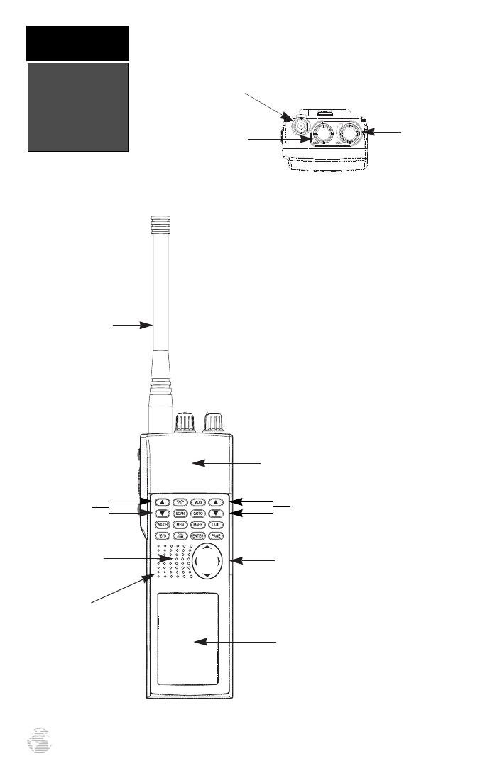
Speaker
Arrow Keypad
Microphone
Channel
Selection Arrow
Keys
Map Scale
Zoom Keys
Flex Com
Antenna
LCD Display
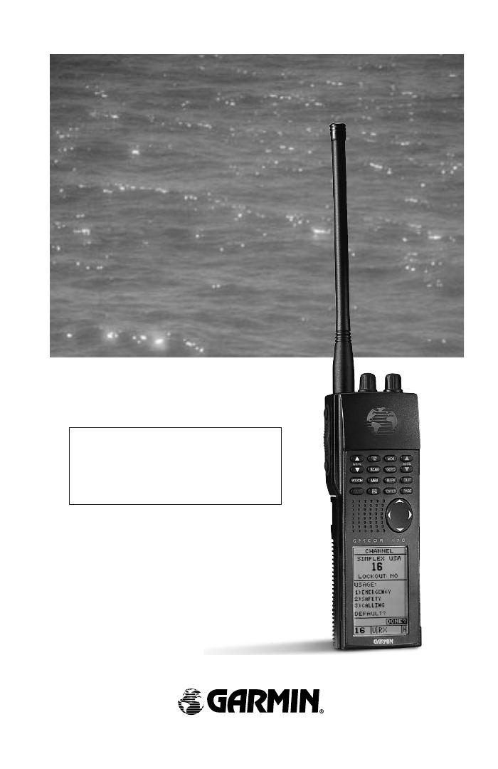
The GPSCOM 170 combines a 12 paral-
lel channel GPS receiver with a 5 watt
marine VHF communications transceiver in
a convenient handheld package. A keypad
located on the front of the unit provides
control of the navigation and communica-
tion functions. The 16/9 key allows for one
button selection of channel 16 or 9. Knobs
for controlling squelch, power and volume
are located on top of the unit. The micro-
phone is located in the lower left speaker
area.
Front View
Internal GPS
Antenna
Squelch
Control
Volume
Control
BNC Antenna
Connector
Top View
Unit
Description
introduction
2
170 manual pages rev D 9/21/98 9:23 AM Page 2

External GPS
Antenna Connector
Power/Data/Ext
Spk/Ext Mic
Cable
Connector
PTT Switch
Backlight
Button
Transmit Power
Button
Charger/AC Adapter
Connector
H/L
The backlight button, transmitting power/override button, charger/AC adapter connec-
tor, and push-to-talk (PTT) switch are located on the left side of the unit. The connector for
the external GPS antenna and power/data/ext speaker/ext mic cable are located on the right
side. A removable Ni-Cad battery pack powers the unit and attaches to the back. See
Appendix B for instructions on installing and removing the battery pack.
Side Views
Removable
Battery Pack
Unit
Description
introduction
3
H/L
170 manual pages rev D 9/21/98 9:23 AM Page 3

K
Use the two-speed ARROW KEYPAD to enter data. Press on a particular
arrow key once to scroll through data options slowly. Press and hold down an
arrow key for faster scrolling.
Use the UP and DOWN arrow keys to select alphanumerical characters and
menu choices, and to move the field highlight from field to field.
The MOB key performs the man overboard function. This marks the current
position, and always displays your current range and bearing from this posi-
tion.
The MARK key captures a position and displays the mark position page.
The QUIT key returns you to a previous page, or clears data entry and restores
a data field’s previous value.
K
The PAGE key scrolls through the main data pages in sequence and returns the
display from a submenu page to a main page. It also displays the message
screen when a message alert appears.
The GOTO key displays the GOTO waypoint page, allowing you to select the
destination waypoint.
B
Use the LEFT and RIGHT arrow keys to move the selected character field, and
to move the highlight from field to field. The left arrow key is also used to clear
a selected field.
U
D
L
R
E
The ENTER key confirms data entry and on-screen responses. This key also
activates highlighted fields to allow data entry.
Keys and
Controls
introduction
4
G
U
D
ZOOM
The MAP SCALE ZOOM keys select the desired map range from 0.2 to 320
nm.
P
Q
170 manual pages rev D 9/21/98 9:23 AM Page 4

The WX/CH key places the unit in weather channel receive mode.
The SCAN key puts the unit into the “all scan” or the “memory scan” mode.
W
S
The ON/OFF/VOLUME control turns the unit on and off and adjusts the volume
level.
The GPSCOM key lets you choose between the main GPS and main communication
pages.
The PUSH-TO-TALK (PTT) switch activates the GPSCOM 170 transmitter on the
active frequency.
The SQUELCH control eliminates receiver background noise and allows only received
transmissions to be heard.
The BACKLIGHT button illuminates the arrow keypad and LCD Screen through four
levels of backlighting (three levels of brightness and off).
C
Keys and
Controls
introduction
5
T
The DUAL/TRI key activates dual and tri watch monitoring.
N
The 16/9 key selects channel 16 or 9 for immediate use.
M
The MEM key accesses the memory setup page which enables you to
program channels into memory.
U
D
CHAN
The CHANNEL SELECTION arrow keys are used to select channels. The channel
number can be increased or decreased one with each press, or if held will continue to
increase or decrease the number as long as the key is held.
H/L
The TRANSMIT POWER BUTTON selects one or five watts of transmit power.
170 manual pages rev D 9/21/98 9:23 AM Page 5

Getting Started
The GPSCOM 170 is a powerful navigation and com-
munication tool that offers mariners a host of advanced
features that help make boating safer and more efficient.
The getting started tour is designed to quickly guide you
through basic features and functions of the unit. Once
you’ve completed the tour and become familiar with the
main pages and features of the unit, refer to the reference
section for complete instructions on performing specific
tasks and functions.
The getting started tour assumes you have initialized
the unit according to the instructions given in Appendix
A, and have not changed any of the default settings. If
you have changed any settings, the descriptions and pic-
tures used may not match your configuration.
Powering Up
To turn the GPSCOM 170 on:
1. Turn the VOL control clockwise.
The welcome page will be displayed while the unit
conducts a self test. Once testing is complete, the wel-
come page will be replaced by the satellite status page
and the GPSCOM 170 will begin acquiring satellite data.
Satellite Status Page
The satellite status page provides a visual reference of
satellite acquisition and receiver status, with a signal
strength bar graph and a satellite sky view in the center
of the page. The accuracy of your position is shown in the
upper right hand side of the page.
The satellite sky view and signal strength bars give
you an indication of what satellites are visible to the
receiver and whether they are being tracked. Satellites,
labeled with numbers and letters, are placed on the page
indicating their position in the sky.
The signal strength bars show how strong the signal
is from each satellite being tracked: The taller the bar, the
stronger the signal. For more information on the satellite
status page, see page 18.
You’ll know you have a fix when a 2D or 3D status
appears in the status field or the receiver automatically
transitions to the position page. If you encounter difficul-
ty acquiring satellite signals, see Appendix A.
Important!
Make sure you charge the
Ni-Cad battery pack for 14
hours before using your
GPSCOM 170 to ensure
optimum capacity and per-
formance. Note: When
charging the battery pack,
turn the unit off to ensure a
full charge. Complete
instructions on charging the
pack are in Appendix B.
The signal strength bars on
the satellite status page give
you an indication of what
satellites are visible to the
receiver, whether or not
they’re being used to calcu-
late a position fix, and the
signal quality.
Acquiring
Satellites
Getting
Started
6
170 manual pages rev D 9/21/98 9:23 AM Page 6
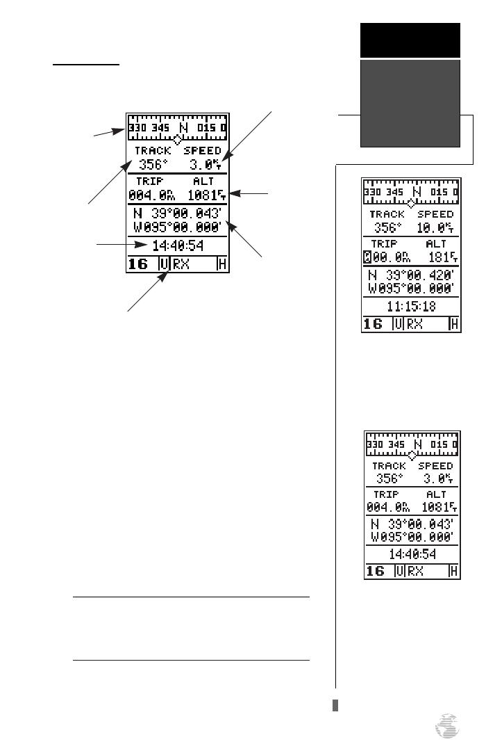
Position Page
The position page shows where you are, what direc-
tion you’re heading and how fast you’re going. The
graphic compass at the top of the page indicates the
direction you’re moving. The four user-selectable data
fields below the compass tape show your current course
and speed over ground, along with a resettable trip
odometer and altitude display. Your current latitude and
longitude, along with a 12/24-hour clock, appear at the
bottom of the page.
The VHF status field appears at the bottom of every
page. It displays (from left to right) the current channel,
band of operation, operating mode, and output power
level. The VHF status field elements are discussed in
detail in the reference section.
The graphic compass display is designed to show your cur-
rent track and does not serve as a true magnetic compass
while you’re standing still.
Position Page
Getting
Started
7
Graphic
Compass
Tape
Current Track
Time of Day
Speed Over Ground
Position
Coordinates
Altitude
VHF Status Field
!
#
The position page also fea-
tures a resettable trip
odometer to keep track of
your distance traveled.
In addition to displaying
your position coordinates,
the position page shows
your track and speed over
the ground.
170 manual pages rev D 9/21/98 9:23 AM Page 7
Marking a Position
Now that you’ve acquired a position, let’s mark it as a
waypoint for future reference.
1.
Press
the
K
key
to capture and hold your posi-
tion.
To mark a position, you must have obtained a 2D or 3D
fix, or have the receiver in simulator mode. If you try to
mark a position without a position fix, you will be alerted
with a ‘No Position’ message.
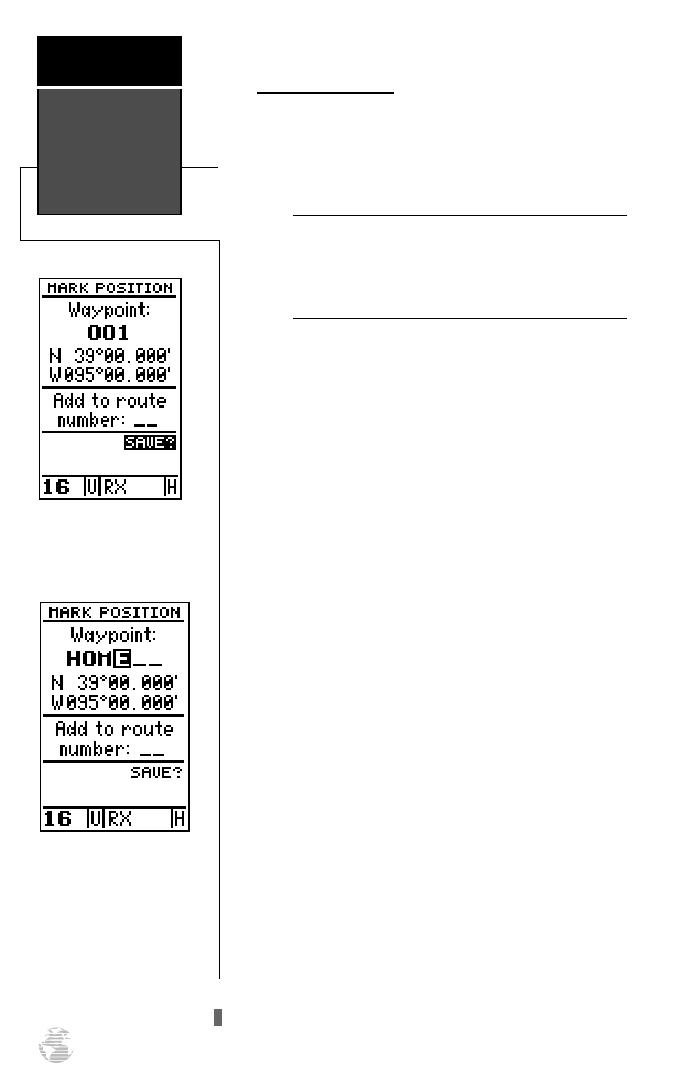
The mark position page will appear, showing the cap-
tured position and a default 3-digit waypoint name, 001.
Let’s change the name to something more meaningful,
like ‘HOME’.
1.
Use the arrow keypad to move the field highlight from
the ‘SAVE?’ field to the ‘Waypoint’ field.
2.
Press
E
and the left arrow key to clear the
default waypoint name.
3.
Press and hold the up arrow key
t
o scroll through the
alphabet until the letter ‘H’ appears.
4. Press the right arrow key once to move the character
highlight to the next character space.
5. Repeat steps 3 and 4 until the word ‘HOME’ is displayed.
6. Press
E
to complete entry of the name.
7. Press the down arrow key once to return the field high-
light to the ‘SAVE’ field.
8. Press
E
to confirm that you want to save the posi-
tion as a waypoint named ‘HOME’.
The mark position page will now be replaced by the
position page (the page displayed prior to pressing
MARK. The ‘HOME’ waypoint is now stored in the
GPSCOM 170’s memory, and will remain there until you
manually remove it or clear the receiver’s memory. For
more on waypoint management, see pages 22-28.
To save a waypoint with the
three digit name, simply
press ENTER on ‘SAVE’.
Marking a
Position
Getting
Started
8
!
#
The arrow keypad is used
for all data entry. Use the
UP and DOWN keys to
select letters, numbers, or
menu options; use the LEFT
and RIGHT keys to move
the cursor forward or back-
ward along the line.
170 manual pages rev D 9/21/98 9:23 AM Page 8

Using the Position and Map Pages
Now that you’ve marked a position, it’s time to take a
brisk walk using the position and moving map pages to
watch your every move. You will need to walk for at least
the time stated in the below steps.to get a much better
indication of how the GPSCOM 170’s steering guidance
and mapping features work.
1. Walk in a straight line for 3-4 minutes at a fast pace and
watch the position page. You can time your distance
with the on-screen clock.
The direction you are moving (your track) and your
speed are displayed on the upper part of the screen, just
below the graphic compass display. The latitude, longi-
tude and approximate altitude of your position–along
with a resettable trip odometer–are continuously dis-
played in the middle of the page, with the time of day dis-
played below.
Now let’s change the display to the moving map page
and watch the track log of our walk:
1. Press the
P
key to change from the position page
to the map page.
Position and
Map Pages
Getting
Started
9
Map Page
The map page displays your
present position as a dia-
mond icon and provides a
real time graphic ‘bread-
crumb’ display of your track
right on screen.
The moving map’s default
setting is track up orienta-
tion. ‘Track up’ means that
your current direction of
travel is always up (or
towards the top of) the
screen. It can also be set for
north up, or desired track up
orientation by using the map
setup page.
170 manual pages rev D 9/21/98 9:23 AM Page 9
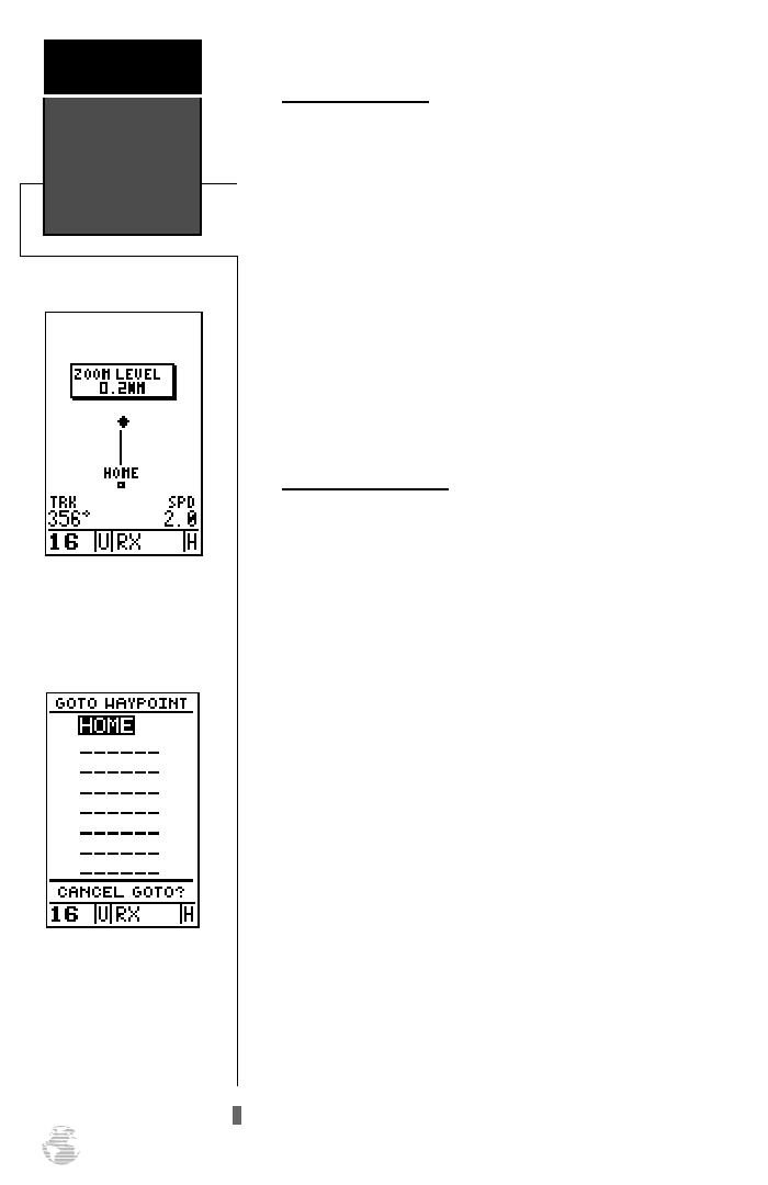
Moving Map Pages
The GPSCOM 170’s next page, the moving map page,
shows your movement as a track log, with your present
position shown as a diamond icon in the center of the
map. You’ll notice the black square below the diamond,
which represents the position you just created (‘HOME’),
and the line between the two, which shows your track.
Nearby waypoints are represented as squares, with
the waypoint name listed above the square. When you
want to change the map scale, simply use the up and
down arrow zoom keys to select the desired scale.
1. Now turn 90º to your right and continue walking at a
fast pace for another 2-3 minutes. Notice how the dis-
play changes, always keeping the direction you are
moving at the top of the map.
Going To a Waypoint
Once you’ve stored a waypoint in memory, you can
use the GPSCOM 170 to guide you to it by performing a
simple GOTO. A GOTO is really nothing more than the
receiver drawing a straight-line course from your present
position to the destination you’ve selected. To see how it
works, let’s try navigating back to our starting position,
the HOME waypoint.
To select a GOTO destination:
1. Press
G
.
2. The
G
waypoint page will appear, displaying all
the waypoints in memory in alphabetical order.
3. Use the arrow keypad to highlight the ‘HOME’
waypoint.
4. Press
E
to confirm that you want to navigate to
the displayed waypoint.
The GOTO waypoint page
allows you to select your
destination from a list of all
available waypoints in the
GPSCOM 170’s memory.
Moving Map
Page
Getting
Started
10
When you want to change
the map scale, simply use
the up and down arrow
zoom keys to select the
desired scale.
170 manual pages rev D 9/21/98 9:23 AM Page 10
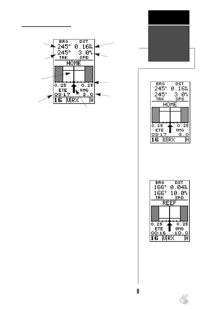
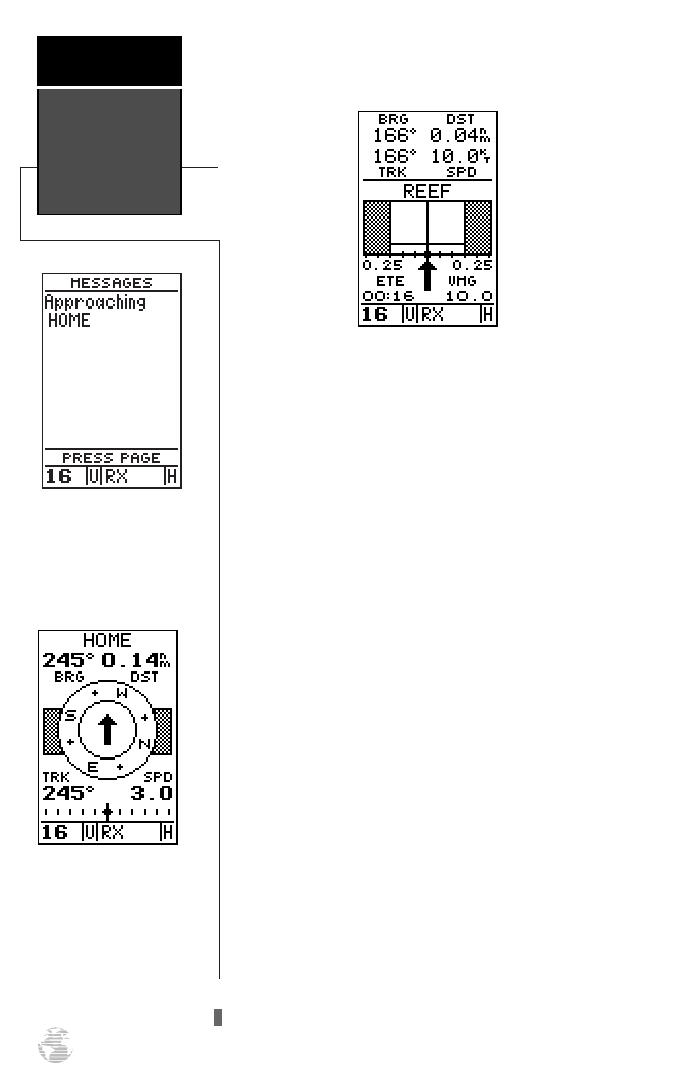
Using the Highway Page
The GPSCOM 170’s highway page provides graphic
steering guidance to a destination, with an emphasis on a
straight–line course to the desired waypoint and the dis-
tance and direction you are off course. The bearing and
distance to a waypoint, along with your current track and
speed, are displayed at the top of the screen, with your
estimated time enroute (ETE) and velocity made good
(VMG), or the rate you are closing in on your destination,
shown at the bottom.
As you head toward your destination, the middle sec-
tion of the screen provides visual guidance to your way-
point on a moving graphic ‘highway’. The moving arrow
just below the course deviation scale always points to
your selected waypoint relative to the direction you are
moving.
Your present position is represented by the diamond
in the center of the course deviation scale. The line down
the middle of the highway represents your desired track.
As you navigate toward a waypoint, the highway will
actually move, indicating the direction you’re off course,
relative to the position square on the CDI scale. To stay
on course simply steer toward the center of the highway.
As you approach a way-
point, a horizontal ‘finish
line’ will move toward the
bottom of the highway.
Your present position is rep-
resented by the square in
the center of the course
deviation scale.
Using The
Highway Page
Getting
Started
11
Distance to
Waypoint
Track Over
Ground
Bearing to
Waypoint
Estimated
Time Enroute
Velocity
Made Good
Speed Over
Ground
Graphic
Highway
Course
Deviation
Scale
Pointer to selected
waypoint
170 manual pages rev D 9/21/98 9:23 AM Page 11
If you do get off course by more than 1/5th of the
selected CDI range, the exact distance you are off course
will be displayed where the CDI scale normally appears.
As you approach a waypoint, a horizontal ‘finish line’ will
move toward the bottom of the highway. When the finish
line reaches the CDI scale, you’ve arrived at your desti-
nation. Whenever the unit has something it needs to tell
you, a message indicator will flash on screen. When you
are less than one minute from reaching your HOME way-
point, the message box will begin flashing.
1. To view a message, press
P
when the message
indicator appears.
2. Press
P
to return to the previous page.
There’s also a compass page to helps provide better
steering guidance where straight–line navigation is not
possible.
To select the compass page:
1. While viewing the highway page, press
E
twice.
The compass page will now become the displayed
navigation page. This page provides a directional pointer
to your destination by using a rotating compass display to
show direction of travel. It provides better steering guid-
ance at slower speeds for travel with many directional
changes.
To switch back to the highway page:
1. Press
E
twice.
Compass Page
The GPSCOM 170 will also
provide steering guidance
with a graphic compass.
Compass &
Message Page
Getting
Started
12
Message Page
Once you are one minute
from the destination, an
arrival message will appear
on the message page.
170 manual pages rev D 9/21/98 9:23 AM Page 12
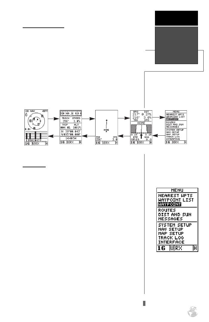
GPS Page Sequence
Now that you’ve arrived ‘HOME’, let’s take a minute to
see how the GPSCOM 170’s main GPS pages work
together. The unit features five main pages, which are
linked together in a chain. You can quickly scroll through
the pages in either direction using the
P
and
Q
keys.
1. Press
P
to scroll through the five main pages in
sequence.
2. Press
Q
to scroll through pages in the opposite
direction.
Menu Page
You’ve already seen the first four pages in action by
acquiring satellites, marking a position and navigating to
a destination. The last page available from the main GPS
page sequence is the menu page, which provides access
to the GPSCOM 170’s waypoint management, route,
track log and setup features. The 11 submenus are divid-
ed into categories by function.
To select a submenu from the menu page:
1. Press
P
or
Q
until the menu page appears.
2. Use the arrow keypad to highlight the submenu you
want to view.
3. Press
E
to access the submenu.
You’ve now gone through the basic operation of the
navigation portion of your new GPSCOM 170. Now let’s
move on to using the VHF radio.
Use the arrow keypad to
select a submenu from the
menu page. Press ENTER
to access the selected sub-
menu.
GPS Page
Sequence
Getting
Started
13
Highway Page
Menu Page
Position Page
Satellite Page
Map Page
170 manual pages rev D 9/21/98 9:23 AM Page 13

Using the VHF Transceiver
The first step in using the VHF transceiver is to make
sure the volume and squelch controls are set correctly for
proper reception.
1. Turn the VOL control clockwise to turn the unit on.
2. Rotate the SQL control fully counterclockwise. This
state is known as “squelch off”. Increase the volume
to achieve a comfortable listening level.
3. Slowly turn the SQL control clockwise and stop slightly
past the point where the noise disappears. This condi-
tion is known as the “squelch threshold”.
If the knob is turned past this point, weak signals
may not be received. No noise and no signals are received
until a signal with sufficient strength is received that
exceeds the squelch threshold. When the GPSCOM 170
is in receive mode, ‘RX’ is displayed in the VHF status
bar.
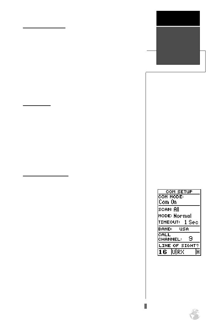
VHF Communication Pages
To move back and forth between the GPS and VHF
pages, press
C
. There are three com VHF pages in a
continuous loop: channel definition, com setup, and
memory bank. Press
C
to exit the GPS pages and
enter the com pages. Try scrolling through the com pages
by pressing
P
You can also scroll in the opposite
direction or return to a previous page by pressing
Q
.
The function of each of the com pages is discussed in
detail in the reference section.
The current channel will
always be displayed at the
bottom left of every page.
Using the VHF
Transceiver
Getting
Started
14
Important!
We strongly recommend
obtaining a marine radio
user’s guide such as
“Maritime Radio User’s
Handbook” published by
the RTCM (Radio
Technical Commission
For Maritime Services),
Washington, D.C., to
ensure proper radio oper-
ation and protocol.
Improper usage can result
in fines levied on
mariners by the FCC.
Squelch
Control
Volume
Control
Com Setup Page
Channel Page
Mem Bank Page
P
Q
170 manual pages rev D 9/21/98 9:23 AM Page 14
Selecting a Channel
The GPSCOM 170 operates on all U.S., Canadian,
and International Marine VHF radio channels.
To select a channel from any page:
1. Use the UP and DOWN channel selection arrow keys
to select the desired channel. The channel number will
increase or decrease with each press–or if held, will
continue to change the number as long as the key is
held. The selected channel will always be displayed at
the left hand side of VHF status bar.
Transmitting
To transmit:
1. Press the push-to-talk (PTT) button. ‘TX’ appears in the
VHF status bar when the PTT button is pressed. Speak
slowly and clearly into the microphone. Hold the unit
about 1/2 to 1 inch from your mouth.
2. Release the PTT button when you are finished
speaking.
Tips on Transmitting
•
Transmitting without an antenna connected to the
GPSCOM 170 may damage the unit. See Appendix
B for instructions on installing and removing the
antenna. The GPSCOM 170 will not transmit using
external power without the battery pack. Make sure
the battery pack is installed.
•
If the PTT button is held in for more than 35 sec-
onds, the transmitter will automatically shut off.
The message ‘Stuck PTT’ will also be displayed on
the message page.
•
The GPSCOM 170 gives you the option of trans-
mitting using 1 watt or 5 watts of power.
Transmitting at 1 watt power is a nice option so that
short-range conversations won’t interfere with a
large number of boaters. Transmitting at 1 watt also
prolongs battery life.
To switch between high and low power:
1. Press the transmitting power button to switch between
low and high power.
Important!
Certain channels are set aside
to be used by authorized sta-
tions for specific purposes,
depending on the type of ves-
sel (commercial or non-com-
mercial). Full familiarization
with channel usage is essen-
tial when selecting a channel.
An ‘H’ will be displayed in
the right–hand side of the
VHF status field for 5 watt
operation, and an ‘L’ for 1
watt .
Transmitting
Getting
Started
15
170 manual pages rev D 9/21/98 9:23 AM Page 15
/