Generac 005747-1 Owner's manual
- Category
- Power generators
- Type
- Owner's manual
This manual is also suitable for
Page is loading ...

introduction.............................................................1
ReadthisManualThoroughly.................................1
Safety Rules...........................................................1
StandardsIndex.............................................................3
Generalinformation................................................4
1.1 Unpacking......................................................................4
1.2 Assembly.......................................................................4
Maintenance.........................................................12
3.1 MaintenanceSchedule.................................................12
3.2 ProductSpecifications..................................................12
3.3 GeneralRecommendations...........................................13
3.4 ServiceAirFilter...........................................................14
3.5 CleanSparkArrestorScreen.........................................14
3.6 General........................................................................14
3.7 LongTermStorage.......................................................15
3.8 OtherStorageTips.......................................................15
Operation................................................................5
2.1 Knowthe Generator.......................................................5
2.2 Hourmeter- NoReset....................................................6
2.3 Hourmeter- With Reset..................................................6
2.4 CordSetsandConnectionPlugs....................................7
2.5 How to Usethe Generator..............................................7
2.6 Don't Overloadthe Generator..........................................9
2.7 WattageReferenceGuide...............................................9
2.8 BeforeStartingthe Generator.........................................9
2.9 ToStartthe Engine.......................................................10
2.10 Stoppingthe Engine.....................................................11
2.11 Low Oil PressureShutdownSystem.............................11
2.12 Chargingthe Battery(XG7OOOE& XG8OOOE)................11
BatteryService.....................................................15
4.1 BatteryReplacement(XG7OOOE&XG8OOOE)...............15
Troubleshooting....................................................17
5.1 TroubleshootingGuide..................................................17
Notes....................................................................18
Warranty...............................................................lg
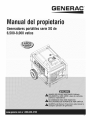
Manualdelpropietario.....................................23
Manueld'entretien............................................45
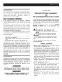
WARNING!
California Proposition 65
Engine exhaust and some of its constituents are known to the state of California to cause cancer,
birth defects, and other reproductive harm.
WARNING!
California Proposition 65
This product contains or emits chemicals known to the state of California to cause cancer,
birth defects, and other reproductive harm.

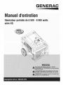
iNTRODUCTiON
Thankyou for purchasingthis modelby GeneracPowerSystems,
Inc. This model is a compact, high performance, air-cooled,
engine driven generatordesigned to supply electrical power to
operateelectrical loads where no utility power is availableor in
placeof utility dueto a poweroutage.
READTHiSMANUALTHOROUGHLY
If any portion of this manual is not understood, contact the
nearest Authorized Dealerfor starting, operating and servicing
procedures.
The operator is responsible for proper and safe use of the
equipment.We strongly recommendthat the operator read this
manualandthoroughlyunderstandallinstructionsbeforeusingthe
equipment.Wealsostronglyrecommendinstructingotherusersto
properlystart andoperatethe unit.This preparesthem ifthey need
to operatetheequipmentin an emergency.
Thegeneratorcan operatesafely,efficiently and reliablyonly if it
is properlylocated,operatedand maintained.Beforeoperatingor
servicingthe generator:
• Becomefamiliar with and strictly adhereto all local, stateand
nationalcodes and regulations.
• Study all safety warnings in this manual and on the product
carefully.
• Becomefamiliar with this manualandthe unit beforeuse.
Themanufacturercannot anticipateevery possiblecircumstance
that might involvea hazard.Thewarnings in this manual,and on
tags and decals affixedto the unit are,therefore,not all inclusive.
If usinga procedure,work method or operatingtechniquethat the
manufacturerdoes not specifically recommend,ensurethat it is
safe for others. Also make sure the procedure,work method or
operatingtechniqueutilizeddoes not renderthe generatorunsafe.
THE INFORMATIONCONTAINEDHEREIN WAS BASED ON
MACHINESIN PRODUCTIONAT THE TIME OF PUBLICATION.
GENERACRESERVESTHERIGHTTOMODIFYTHISMANUALAT
ANYTIME.
SAFETYRULES
Throughoutthis publication,and on tags and decals affixedto the
generator,DANGER,WARNING,CAUTIONand NOTEblocks are
usedto alert personnelto special instructionsabout a particular
operation that may be hazardous if performed incorrectly or
carelessly. Observe them carefully. Their definitions are as
follows:
iNDICATESA HAZARDOUSSiTUATiONORACTIONWHICH,IF
NOTAVOIDED,WiLLRESULTiN DEATHORSERIOUSiNJURY.
Indicatesa hazardoussituationor actionwhich,ifnot
avoided, couldresultin deathor seriousinjury.
ACAUTION!
Indicatesa hazardoussituationor actionwhich,if not
avoided, couldresultin minoror moderateinjury.
NOTE:
Notescontainadditionalinformationimportanttoa procedure
and will be foundwithin theregulartextbodyofthismanual.
These safety warnings cannot eliminate the hazards that they
indicate. Common sense and strict compliancewith the special
instructionswhileperforming theaction or serviceareessentialto
preventingaccidents.
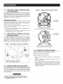
Four commonly used safety symbols accompany the DANGER,
WARNINGand CAUTIONblocks. The type of information each
indicatesis asfollows:
,_This symbol points out important safety
information that, if not followed, could
endanger personal safety and/or property of
others.
This symbol points out potential explosion
hazard.
This symbol points out potential fire hazard.
This symbol points out potential electrical
shock hazard.
GENERAL HAZARDS
• NEVERoperatein an enclosedarea, in a vehicle, or indoors
EVENIFdoorsand windows areopen.
• For safety reasons, the manufacturer recommendsthat the
maintenanceof this equipmentis carried out by an Authorized
Dealer.Inspectthe generatorregularly,and contactthe nearest
AuthorizedDealerfor parts needingrepairor replacement.
• Operategeneratoronly on levelsurfacesandwhereit will notbe
exposedto excessivemoisture,dirt, dust or corrosivevapors.
• Keep hands, feet, clothing, etc., awayfrom drive belts, fans,
and othermoving parts. Neverremoveany fan guardor shield
whilethe unit isoperating.
• Certain parts of the generator get extremely hot during
operation. Keep clear of the generator until it has cooled to
avoidsevereburns.
• Do NOToperategeneratorinthe rain.
• Do not alter the construction of the generator or change
controlswhich might createan unsafeoperatingcondition.
• Never start or stop the unit with electrical loads connected
to receptaclesAND with connecteddevicesturned ON. Start
the engine and let it stabilize before connecting electrical
loads. Disconnectall electricalloads beforeshutting downthe
generator.
• Do notinsert objectsthrough unit's cooling slots.
• When working on this equipment, remain alert at all times.
Never work on the equipment when physically or mentally
fatigued.

• Neverusethegeneratororanyofitspartsasastep.Stepping
ontheunitcanstressandbreakparts,andmayresultin
dangerousoperatingconditionsfromleakingexhaustgases,
fuelleakage,oilleakage,etc.
• Onelectricstartmodels,disconnectthePOSITIVE(+)battery
cablefromtheenginestarterORtheNEGATIVE(=)battery
cablefromthebatteryterminal,whicheveriseasier,before
transportingthegenerator.
NOTE:
This generatoris equippedwith a spark arrestormuffler. The
spark arrestor must be maintained in effective working order
by the owner/operator.In the State of California, a spark
arrestor is requiredby law (Section 4442 ofthe California
Public Resources Code). Other states may havesimilarlaws.
Federal lawsapply on federallands.
EXHAUST & LOCATIONHAZARDS
• Never operate in an enclosed area or indoors!NEVERuse
in the home,in a vehicle,or in partlyenclosedareassuch
as garages, evenif doors and windowsare open! ONLYuse
outdoors and far from open windows,doors,vents,andinan
areathatwill notaccumulatedeadly exhaust.
Using a generator indoors CAN KILL YOU IN MINUTES,
Generator exhaust contains carbon monoxide. This is
a poison you cannot see or smell,
NEVER use insidea home
or garage, EVEN IF doors
and windows are open.
Only use OUTSIDE and
far away from windows,
doors,and vents.
• The engine exhaustfumes contain carbon monoxide, which
you cannot see or smell. This poisonous gas, if breathedin
sufficientconcentrations,can causeunconsciousnessor even
death.
• Adequate, unobstructed flow of cooling and ventilating air
is critical to correct generator operation. Do not alter the
installation or permit even partial blockage of ventilation
provisions, as this can seriously affect safe operationof the
generator.ThegeneratorMUSTbeoperatedoutdoors.
• This exhaustsystemmust be properlymaintained.Do nothing
that mightrendertheexhaustsystemunsafeorinnoncompliance
with any localcodes and/orstandards.
• Alwaysusea batteryoperatedcarbonmonoxidealarmindoors,
installedaccordingto themanufacturersinstructions.
• If you start to feet sick, dizzy,or weak after the generatorhas
beenrunning,moveto fresh air IMMEDIATELYSeea doctor,as
you couldhavecarbonmonoxidepoisoning.
ELECTRICALHAZARDS
• The generator produces dangerously high voltage when in
operation.Avoidcontactwithbarewires,terminals,connections,
etc., while the unit is running,even on equipmentconnected
to the generator. Ensureall appropriate covers, guards and
barriersarein placebeforeoperatingthegenerator.
• Never handle any kind of electrical cord or device while
standinginwater,while barefootorwhile handsor feet arewet.
DANGEROUSELECTRICALSHOCKMAYRESULT.
• TheNationalElectricCode(NEC)requirestheframe andexternal
electrically conductive parts of the generator be properly
connectedto an approvedearthground.Local electricalcodes
may also require proper grounding of the generator.Consult
with a localelectricianfor groundingrequirementsin thearea.
• Use a groundfault circuit interrupter in any damp or highly
conductivearea(such as metaldecking or steelwork).
• Do not useworn, bare,frayed or otherwisedamagedelectrical
cord setswith the generator.
• Beforeperforminganymaintenanceonthegenerator,disconnect
the enginestarting battery (if equipped)to prevent accidental
start up. Disconnectthe cablefrom the batterypost indicated
by a NEGATIVE,NEGor (-) first. Reconnectthatcable last.
• In caseof accidentcausedby electricshock, immediatelyshut
down the source of electrical power. If this is not possible,
attempt to free the victim from the live conductor. AVOID
DIRECTCONTACTWITH THEVICTIM, Use a non-conducting
implement,such asa rope or board,to freethevictim from the
live conductor.If the victim is unconscious,applyfirst aid and
getimmediatemedical help.
FIREHAZARDS
• GasolineishighlyFLAMMABLEand itsvaporsare EXPLOSIVE.
Do not permitsmoking,open flames, sparksor heat in the
vicinitywhilehandlinggasoline.
• Neveraddfuel whileunit isrunning or hot. Allow engineto cool
completelybeforeaddingfuel.
• Never fill fuel lank indoors,Comply with all laws regulating
storageand handlingof gasoline.
• Do not overfill the fuel tank. Always allow roomfor fuel
expansion. If tank is over=filled,fuel can overflow onto a hot
engineandcauseFIREor an EXPLOSION.Neverstoregenerator
with fuel in tank where gasolinevapors might reachan open
flame, spark or pilot light (as on a furnace, water heateror
clothes dryer). FIREor EXPLOSIONmay result. Allow unit to
cool entirelybeforestorage.
• Wipe up any fuel or oil spills immediately.Ensure that no
combustiblematerialsareleft on or nearthegenerator.Keepthe
areasurroundingthe generatorcleanandfree from debrisand
keepa clearanceof five (5) feet onall side to allow for proper
ventilationofthe generator.

* Donot insert objectsthrough unit's coolingslots.
* Do not operate the generatorif connected electrical devices
overheat,ifelectricaloutputis lost,if engineor generatorsparks
or if flamesor smokeare observedwhile unit is running.
* Keepa fire extinguishernearthe generatorat all times.
STAtVDARDS/#DEX
In the absence of pertinent standards, codes, regulations and
laws, the publishedinformation listed below may be used as a
guidelinefor operation of this equipment. Always referencethe
latestrevisionavailablefor the standardslisted.
1. NFPANo. 70, NFPAHANDBOOKOF NATIONALELECTRIC
CODE.
2. Article X, NATIONALBUILDINGCODE,available from the
American InsuranceAssociation, 85 John Street, NewYork,
N.Y.10038.
3. AGRICULTURALWIRINGHANDBOOK,availablefrom the Food
and EnergyCouncil, 909 UniversityAvenue, Columbia, MO
65201.
4. ASAE EP-3634, INSTALLATIONAND MAINTENANCEOF
FARMSTANDBYELECTRICALSYSTEMS,availablefrom the
AmericanSocietyof AgriculturalEngineers,2950 Niles Road,
St. Joseph,MI49085.
MODELNO:
SERIALNO:
Generator Identification
Uni± I]D
Loci±ions

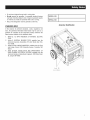
1.1 UNPACKING
• Removeall packagingmaterial.
• Removeseparateaccessorybox.
• Removecarton off the generator.
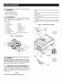
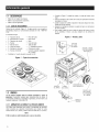
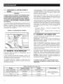
1.1.1 ACCESSORYBOX
Checkall contents(Figure1). If anyparts aremissing or damaged
locatean authorizeddealerat 1=888=436=3722.
Contentsinclude:
• 2-Axle Pins • Oil Filter
• 2- WheelSpacers • Air Filter
• 2- HairPins • SparkPlug
• 2- Wheels • SparkPlugWrench
• 1 - FrameFoot • ShopTowel
• 2 - FrameBolts • 2 - FrameWashers
• 2-Vibration Mounts • Oil Funnel
• 4 - FlangeNuts 12 VoltAdaptorPlugCharger
• 2 - 1 QuartSAE30 Oil Bottles
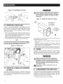
Figure 1 - Accessory Boxes
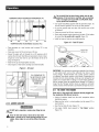
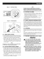
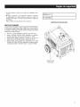
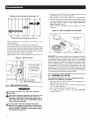
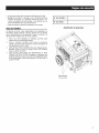
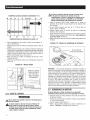
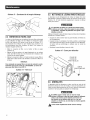
• Referto Figure2 and install the wheel kit and frame foot as
follows:
• Slidethe AxlePin throughthe Wheel,WheelSpacer(Washer)
andthe Frame.
• Installthe Hair Pinto the Axle Pinto securethe wheel. Repeat
forthe oppositeside.
• SecuretheVibrationMountsto theFrameFootwith theincluded
locking nuts.
• To install the Frame Foot, install the Frame Bolts though the
FrameWashers,Frameand Framefoot. Securewith the flange
nuts.
Figure 2 - Wheel and Foot Assembly
FOOT
SECUREWHEEL
ANDAXLEWITH
HAIRPIN
1.2 ASSEMBLY
Read entireOwner's Manual beforeattempting to assemble or
operate the generator. The generator requiressome assembly
prior to usingit. If problemsarisewhenassemblingthe generator,
pleasecallthe GeneratorHelplineat 1=888=436=3722.
1.2.1 ASSEMBLINGTHEWHEELKITANBFRAMEFOOT
Thewheelkit is designedto greatly improvethe portability of the
generator.You will needthe following tools to install the wheel
kit: Pliers,1/2" (13mm) wrenchand a socket wrench with a 1/2"
(13mm) socket.
NOTE:
The wheel kit is notintendedfor over-the-roaduse.
FRAME
WASHER
I FRAME
I BOLT
I
I
WHEELSPACER
(WASHER)
FLANGE
SLIDEAXLE
THROUGHWHEEL
ANDWHEEL
SPACER

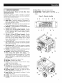
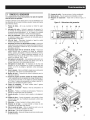
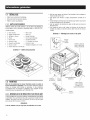
2.1 KNOWTHEGENERATOR
Read the entire Owner's Manual and Safety Rules before
operatingthisgenerater.
Compare the generator to Figures 3 through 6 to become
familiarizedwith thelocationsof variouscontrolsandadjustments.
Savethis manualfor future reference.
1. ChokeKnob- Usedwhen startinga coldengine (Putt/Push).
2. EngineSwitch - Controlsthe operationof the generator.On
electric start models the switch is Start/Run/Stop.On recoil
start modelsthe switch is On/Off.
3. FuelShut Off - Valvebetweenfueltank andcarburetor.Turn
off and run carburetoroutof fuelfor extendedstorage.
4. Panel LED's- Provideilluminationof the control panelwhile
thegeneratoris operating.
5. 120/240 Volt AC, 30 Amp LockingReceptacle- Supplies
electricalpowerfor the operationof 120 and/or240 VoltAC,
30 Amp, single-phase,60 Hz, electrical lighting, appliance,
tool andmotor loads.
5. 120 Volt AC,20 Amp,GFCiDuplexReceptacle- Supplies
electrical power for the operationof 120 Volt AC, 20 Amp,
single-phase, 60 Hz electrical lighting, appliance,tool and
motor loads. It also provides protection with an Integral
Ground Fault Circuit Interrupter, complete with a press to
"Test"and "Reset"button.
7. Circuit Breakers (AC)- Each20 Amp receptacleis provided
with a push-to-reset circuit breakerto protectthe generator
againstelectricaloverload.
8. Circuit Breakers (AC)- The30 Amp receptacleis protected
with a pair of push-to-reset circuit breakersto protect the
generatoragainstelectricaloverload.
9. PowerBar- Indicatesthe amountof power being usedfrom
thegenerator;each sectionisapproximately25%
10. Hourmeter- Providesoperatinghoursfor Service Intervals.
11. Battery Charger Input (Electric Start Models) - This
receptacleallowsthecapabilityto rechargethe12 VDCengine
starting battery with the 12 Volt Adaptor Plug Charger.The
batteryisprotectedby a 1.50 Ampin-linefuse which is inside
thecontrol panel.
12. FuelTank- Tankholds9 U.S.gallonsoffuel.
13. FuelGauge- Showsfuel levelin tank.
14. Handles - Pivot and retractfor storage. Press the spring-
loadedbuttonto move handles.
15. Oil Fill - Checkoil levelandadd oil here.
16. GroundingLug - Groundthe generatorto an approvedearth
groundhere.See"GroundingtheGenerator"for details.
17. Muffler- Includesthe sparkarrestor andquietsthe engine.
18. Spark Plug Location - The spark plug ignites the Air/Fuel
Mixture(Sidepanelmust be removed).
lg. Engine Oil Filter- Filtersengineoil; seeSection 3.1 for the
properservice intervals.
20. Air Filter- Filtersintakeair as it is drawn intothe engine.
21. Oil Drain- Drain valveto remove used oil from the engine
crankcase.
22. RecoilStarter - Useto start enginemanually.
23. Roll OverValve- Passesfuel vaporsto the engine.
24. Recovery Hose - Install between roll over valve and the
engine.
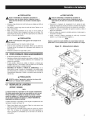
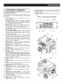
Figure 3 - Generator Locations
1 2 5 B 9 10 11
@ [_ , ,,,. ,, , ,:, @
4 7
12
13
17
15 18
24
23
18
1
22
2O

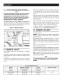
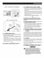
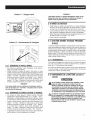
2.1.1 BATTERYCONNECtiONfXGTOOOE& XGSOOOE)
NOTE:
The battery shippedwith the generatorhasbeen fully charged.
A battery may losesomeof itschargewhennot in use for
prolongedperiodsoftime. ifthe battery is unable to crank
the engine,pluginthe 12V chargerincludedin the accessory
box (seethe Chargingthe Battery section).RUNNINGTHE
GENERATORDOESNOTCHARGETHEBATTERY.
The positive battery wire was deliberately left detached for
shipping. To operatethe unit, attachthis wire to the terminal on
the startermotor as shown.Do notovertighten.Slidethe attached
rubber bootoverthe starterterminal.SeeFigure4.
Figure4 - Battery Connection
2.2 HOURIVIETER-NO BESET
The Hourmeter tracks hours of operation
maintenance:
for scheduled
Therewill be a onetime breakin "CHGOIL"messagethat flashes
with the elapsedtime in hoursand tenths after thefirst 30 hours
of operation.
This messagewill actuallybeginflashing at 29 hoursand disable
itself at 31 hours providing a two hour window to perform the
service.
Therewill be a subsequent"CHGOIL"messageevery 100 hours.
Themessagewilt flash one hour beforeand one hourafter each
100 hour interval,again providinga two hourwindow to perform
service.
Every200 hoursthe "SVC"icon on the lower left handcorner of
thedisplay will flash. Themessagewill flash one hourbeforeand
onehour aftereach200 hourintervalprovidingatwo hourwindow
to perform service.
Whenthe hour meter is inthe FlashAlert mode, the maintenance
message will always alternate with elapsedtime in hours and
tenths. The hours wilt flash four times, then alternate with the
maintenancemessagefourtimes untilthemeter resetsitself.
* 100 hours- CHGOIL-- OilOhangeInterval(Every100 hrs)
* 200 hours- SVC-- Air FilterInterval(Every200 hrs)
2.3 HOURIVlETFR-WiTHRESET
TheHourmetertrackshoursofoperationforscheduledmaintenance
(seechart) (Figure5).
Operation: Pushand releasethe reset button to toggle between
screens. The hours count backwards from the set interval as
shown in the chart.
Whenthe meter reaches5 hours,thetext"CHGOIL"(or "SVCAIR
FILTER"or "OHGPLUG")will flash continuallyfor two minutes.
Afterthis time,the meterwill go backto displayingthetotal hours
of the unit (for 2 minutes). This cyte will repeatfor the entire 5
hours.
When the service interval reaches zero hours, the text "NOW"
replacesthe hoursremaining.
Fora newgeneratorfor instance,the messagewill say"OHGOIL"
thenflash "in30". This meansthat in 30 hours, theoil wilt needto
be changed. Pressingthe button a few moretimes will bring the
meter backto the screenthat shows thetotal hoursrun.
Reset: Toggleto the alert that you wish to reset then hold the
buttondownfor 9 seconds.Themaintenancehoursareresetwhen
thedisplay shows "0000.0".
Note:
Thehourglass graphicwillflash on and offwhenthe engine
is running.Thissignifiesthatthe meteristrackinghoursof
operation.
Message
CHGOIL
CHGOIL
SVCAIRFILTER
CHGPLUG
Nourmeter(With Reset)Chart
Duration ofmessageFrequencyof Message
Initial break-inperiod
Re-occuring
Re-occuring
Re-occuring
interval
First30 Hours
100 hours
200 hours
200 hours
ON/OFFfor 2 minutesin a5
hour period

Figure 5 - Hourmeter
0000.0
HOURGLASS RESETBUTTON
GRAPHIC (IF EQUIPPED)
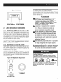
2.4 CORDSETSANOCONNECTIONPLUGS
2.4.1 120VAC,20 AMP,GFC/DUPLEXRECEPTACLE
This is a 120 Volt outletprotectedagainst overloadby a 20 Amp
push-to-resetcircuitbreaker(Figure6). Useeachsocketto power
120 VoltAO,singlephase,60 Hzelectricalloadsrequiringupto a
combined 2400 watts (2.4 kW) or 20 Amps of current. Useonly
high quality,well-insulated, 3-wire grounded cord sets ratedfor
125 Volts at 20 Amps (or greater).
Keep extensioncords as short as possible, preferablyless than
15 feet long, to preventvoltagedrop and possibleoverheatingof
wires.
2.4.2 120/240VAC,30 AMPRECEPTACLE
Use a NEMA L14-30 plug with this receptacle (rotate to lock!
unlock). Oonnecta suitable4-wire groundedcord set to the plug
andto thedesiredtoad.Thecordset shouldbe ratedfor 250 Volts
ACat30 Amps (or greater)(Figure6).
Use this receptacleto operate120 Volt AC, 60 Hz, singlephase
loads requiringup to 3600 watts (3.6 kW) of powerat 30 Amps
or 240 VoltAC,60 Hz,singlephaseloadsrequiring6,500 to 8000
watts of power,dependingonthemodel.Theoutletis protectedby
a 30 Ampcircuit breaker.
Figure 6 - Generator Receptacles
120VAC20A
GFC]RECEPTACLE
O
120/240VAC30A
RECEPTACLE
2.5 HOW TOUSETHEGENERATOR
Seethe "To Startthe Engine"sectionfor how to safelystart and
stop the generatorand how to connect and disconnect loads. If
there are any problems operatingthe generator,pleasecall the
generatorhelplineat 1-888-436-3722.
_t ever operate in an enclosed area or indoors!
NEVER use in the home, in a vehicle, or in
partly enclosed areas such as garages, EVEN
IF doors and windows are open! ONLY use
outdoors and far from open windows, doors,
vents, and in an area that will not accumulate
deadly exhaust.
_t The engine exhaust fumes contain carbon
monoxide, which can you cannot see or smell.
This poisonous gas, if breathed in sufficient
concentrations, can cause unconsciousness or
even death.
_t Adequate, unobstructed flow of cooling and
ventilating air is critical to correct generator
operation. Do not alter the installation or permit
even partial blockage of ventilation provisions,
as this can seriously affect safe operation
of the generator. The generator MUST be
operated outdoors.
_t This exhaust system must be properly
maintained. Do nothing that might render the
exhaust system unsafe or in noncompliance
with any local codes and/or standards.
_t Always use a battery operated carbon
monoxide alarm indoors, installed according to
the manufacturers instructions.
Using a generator indoors CAN KiLL YOU IN MINUTES,
Generator exhaust contains carbon monoxide. This is
a poison you cannot see or smell.
NEVER use inside a home
or garage, EVEN IF doors
and windows are open.
Only use OUTSIDE and
far away from windows,
doors, and vents.

2.5.1 GROUNDINGTHEGENERATORWHENUSEDASA
PORTABLE
This generator has an equipment ground that connects the
generatorframe componentsto the ground terminals on the AC
output receptacles (see NEC 250.34 (A) for explanation).This
allows the generatorto be used as a portablewithout grounding
the frame ofthe generatorasspecifiedin NEC250.34.
SpecialRequirements
There may be Federalor State OccupationalSafety and Health
Administration(OSHA)regulations,localcodes,or ordinancesthat
applyto the intendeduse ofthe generator.
Pleaseconsult a qualified electrician,electrical inspector, or the
local agencyhavingjurisdiction:
* In some areas,generators are requiredto be registeredwith
local utilitycompanies.
* If the generatoris used at a construction site, there may be
additionalregulationswhich must beobserved.
2.5.2 CONNECTINGTHEGENERATORTO,4BU/LD/NG'S
ELECTRICALSYSTEM
When connecting directly to a building's electrical system, it is
recommended that a manualtransfer switch is used. Connectionsfor
a portable generatorto a building's electricalsystem must be made by
a qualifiedelectrician andin strict compliancewith all national andlocal
electricalcodesand laws.
Figure7 - GeneratorGroundLocation
LOCATION
XG6500&XG7000 GROUNDLOCATION
ANDBRUSHEDALTERNATORXG8000
2.5.3 NEUTRALTOFRAMEGROUNDING
If service work is performed on the alternator,DO NOTdiscard
the white jumper wires from the terminal block to the alternator
ground, located on the rear bearingcarrier. Always make sure
the wires are properlyconnectedbeforeusingthe generatorafter
alternatorservicework is done (Figure8).
Figure8 - NeutraltoFrameGround
NEUTRALTO FRAMEGROUND
DONOTDISCARD
WIRES!
XG7000& 8000 BRUSHLESSALTERNATORONLY
DONOTDISCARD
WIRES!
NEUTRALTO FRAMEGROUNDXG6500,
7000 AND8000 BRUSHEDALTERNATOR
//_Failure to reconnect these wires may create a
potential shock hazard when the generator is
running!
2.5.4 CONNECTINGELECTR/CALLOADS
DONOTconnect240 Volt loadsto 120 Voltreceptacles.
DONOTconnect3 phaseloadsto the generator.
DONOTconnect50 Hzloadsto the generator.
* Let engine stabilize and warm up for a few minutes after
starting.
* Plug in and turn on the desired 120 or 240 Volt AO, single
phase,60 Hzelectricalloads.
* Add up the ratedwatts (or amps) of all loadsto be connected
at one time. This total should no be greaterthan (a) the rated
wattage/amperagecapacity of the generator or (b) circuit
breakerratingofthereceptaclesupplyingthepower.See"Don't
OverloadtheGenerator

2.6 DON'TOVERLOADTHEGENERATOR
Overloadinga generatorin excess of its ratedwattage capacity
can result in damageto the generatorandto connectedelectrical
devices.Observethefollowing to preventoverloadingthe unit:
* Addupthetotal wattageofall electricaldevicesto be connected
at one time. This total should NOT be greater than the
generator'swattagecapacity.
* The ratedwattageof lights can be takenfrom light bulbs. The
ratedwattageof tools, appliancesand motors can usually be
found on a datalabelor decalaffixedto the device.
* If the appliance,toot or motor does not givewattage, multiply
voltstimes ampereratingto determinewatts (voltsx amps =
watts).
* Some electric motors, such as induction types, require about
threetimes morewatts of powerfor startingthan for running.
This surge of power lasts only a few seconds when starting
such motors.Makesureto allowfor high startingwattagewhen
selectingelectricaldevicesto connectto the generator:
1. Figurethe watts neededto start the largestmotor.
2. Add to that figure the running watts of all other connected
loads.
TheWattageReferenceGuideis providedto assist in determining
how many itemsthe generatorcan operateatonetime.
IMPORTANT:Donotoverloadthe generator.Also, do not overload
individual panel receptacles.These outlets are protectedagainst
overload with push-to-reset-type circuit breakers. Read "Don't
OverloadtheGenerator"carefully.
NOTE:
All figuresare approximate.Seedatalabel onappliancefor
wattage requirements.
2.7 WATTAGEREFERENCEGUIDE
Device ................................... RunningWatts
*Air Conditioner(12,000 Btu).......................... 1700
*Air Conditioner(24,000 Btu).......................... 3800
*Air Conditioner(40,000 Btu).......................... 6000
BatteryCharger(20 Amp).............................. 500
BeltSander(3") .................................... 1000
ChainSaw ........................................ 1200
CircularSaw(6-1/2") ........................... 800 to 1000
*Clothes Dryer(Electric) ............................. 5750
*Clothes Dryer(Gas) ................................. 700
*Clothes Washer ................................... 1150
CoffeeMaker ...................................... 1750
*Compressor (1 HP)................................. 2000
*Compressor (3/4 HP)............................... 1800
*Compressor (1/2 HP)............................... 1400
CurlingIron......................................... 700
*Dehumidifier....................................... 650
Disc Sander(9").................................... 1200
EdgeTrimmer....................................... 500
Electric Blanket...................................... 400
Electric NailGun.................................... 1200
Electric Range(per element)........................... 1500
Electric Skillet...................................... 1250
*Freezer............................................ 700
*FurnaceFan(3/5 HP) ................................ 875
*GarageDoorOpener............................ 500to 750
Hair Dryer......................................... 1200
HandDrill .................................... 250to 1100
HedgeTrimmer...................................... 450
Impact Wrench...................................... 500
Iron.............................................. 1200
*Jet Pump ......................................... 800
Lawn Mower....................................... 1200
LightBulb.......................................... 100
Microwave Oven............................... 700to 1000
*Milk Cooler....................................... 1100
OilBurneron Furnace................................. 300
OilFiredSpaceHeater(140,000 Btu) ..................... 400
OilFiredSpaceHeater(85,000 Btu) ...................... 225
OilFiredSpaceHeater(30,000 Btu) ...................... 150
*Paint Sprayer,Airless (1/3 HP) ......................... 600
PaintSprayer,Airless (handheld)......................... 150
Radio ......................................... 50 to 200
*Refrigerator........................................ 700
SlowCooker........................................ 200
*SubmersiblePump (1-1/2 HP) ........................ 2800
*SubmersiblePump (1 HP) ........................... 2000
*SubmersiblePump (1/2 HP).......................... 1500
*Sump Pump................................. 800to 1050
*Table Saw(10") ............................. 1750to 2000
Television..................................... 200to 500
Toaster..................................... 1000to 1650
WeedTrimmer ...................................... 500
* Allow 3 times thelistedwatts for starting these devices.
2.8 BEFORESTARTINGTHEGENERATOR
Priorto operatingthe generator,engineoil and gasolinewill need
to be added,asfollows:
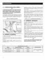
2.8.1 ABB/flGEflG/flEO/L
All oil should meet minimum American PetroleumInstitute (API)
Service Class SJ, SL or better.Use no special additives. Select
the oil's viscosity grade according to the expected operating
temperature(also seechart).
* Above40° F,useSAE30
* Below40° Fand downto 10° F,use10W-30
* Below10° F,use synthetic5W-30
Any attempt tocrankor startthe enginebeforeit has
been properlyserviced with therecommendedoil may
resultin an engine failure.

TEMPERATURE iN DEGREES FAHRENHEIT (°F)
=30 =20 =10 0 1G 20 32 40 55 70+
=30 =20 =10 0 10 20
TEMPERATURE iN DEGREES CELSIUS (°C)
• Placegeneratoron a levelsurface (not to exceed15° in any
direction).
• Cleanareaaroundoil fill andremoveoil fill cap.
• Slowly fill engine with oil through the oil fill opening until it
reachesthefull mark.Stopfilling occasionallyto checkoil level.
(Engineoil is full when levelis up to the threadsof the oil fill
plug,seeFigure9)
• Installoil fill capandfingertighten securely.
• Checkengineoil levelbeforestarting eachtime thereafter.
Figure9 - Oil Level
J m
I ....... J
L__
-- _-Jd
FILLCRANKCASETO
THE BOTTOMOFTHESE
THREADSWITHTHE
RECOMMENDED
ENGINEOIL
u
!
I
2.8.2 AL}D/NGGASOLINE
D0 NOTlighta cigaretteor smoke whenfilling the fuel
tank.
,_ Neverf!ll fuel tankindoors.Never fill fuel tankwhen
engine is runningor hot. Avoid spillinggasoline on a hot
engine.Allowengineto coolentirelybeforefilling fuel
tank.
Do notoverfill the fuel tank.Alwaysleave roomfor fuel
expansion, ifthe fuel tankisoverfilled, fuel canoverflow
onto a hot engine and causeFIREor EXPLOSION.Wipe
up anyspilledfuel immediately.
• Use regularUNLEADEDgasolinewith the generatorengine.Do
not usepremiumgasoline.Do notmix oil with gasoline.
• Do not usegasolinewith morethan 10% alcohol such as E85
or Methanol.
• Cleanareaaroundfuelfill cap, removecap.
• Slowly addunleadedregulargasolineto fueltank. Fillto bottom
of screenfilter.Becarefulnotto overfill (Figure10).
• Installfuelcap andwipe up any spilledgasoline.
Figure 10 - Fuel Fill Level
DONOTFILL
ABOVELIP!
IMPORTANT:Itis importantto preventgum depositsfrom forming
in fuel system parts such as the carburetor,fuel hose or tank
during storage. Alcohol-blendedfuels (called gasohol, ethanol
or methanol)can attract moisture, which leadsto separationand
formationof acids duringstorage.Acidic gascandamagethefuel
system of an enginewhile in storage.Toavoid engineproblems,
the fuel system should be emptiedbefore storage of 30 days or
longer.Seethe "Storage"section. Neveruseengineor carburetor
cleanerproductsinthefueltank aspermanentdamagemay occur.
2.9 TOSTARTTHEENGINE
Never startor stopengine withelectrical devicespluggedinto
thereceptaclesANDdevices turnedon.
• Unplug all electrical loads from the unit's receptaclesbefore
startingthe engine.
• Make surethe unit is in a levelposition (notto exceed15° in
anydirection).
• Openthefuel shut-off valve (Figure11).
• Pull engine CHOKEknob outward to "Full Choke" position
(Figure12).
1o

Figure 11 - Fuel Shut-off Valve
I
2.g.1 MANUAL_ STARTING
• Tostartthe generator,putthe on/off switch inthe ONposition.
• Firmly grasp the recoil handle and pull slowly until increased
resistanceisfelt. Pull rapidlyup and awayto start engine.
• When the engine starts, push choke knob to "1/2 Choke"
position untilthe engine runssmoothly andthenfully in to the
"Run" position. If enginefalters, pull choke knob back out to
"1/2 Choke"position until the engine runs smoothly and then
to "Run" position.
NOTE:
If engine fires,butdoesnotcontinueto run, pull chokeknob
to "Full Choke" andrepeat starting instructions.
2.9.2 ELECTRICSTARtiNG(XGTOOOE& XGSOOOE)__
* Tostartthe engine,pressandhold theStart/Run/Stopswitch in
the "Start" position.Theenginewill crankand attemptto start.
Whenthe enginestarts, releasetheswitch to the runposition.
* When the engine starts, push choke knob to "1/2 Choke"
position untilthe engine runssmoothly andthenfully in to the
"Run" position. If enginefalters, pull choke knob back out to
"1/2 Choke"position until the engine runs smoothly and then
to "Run" position.
* This generatoris also equippedwith a manual recoil starter
which may be usedif the batteryis discharged.
NOTE:
Theswitchmustbe in theRUNposition.Use one of the
generator's receptacleoutletsalongwiththe includedbattery
chargerto chargethe battery while thegenerator is running.
2.10STOPPINGTHEENGINE
* Shut off all loads, then unplug the electrical loads from
generatorpanelreceptacles.Neverstart or stopthe enginewith
electricaldevicespluggedin andturned on.
* Let engine run at no-load for several minutes to stabilizethe
internaltemperaturesof engineandgenerator.
* Move Start/Run/Stopor On/Offswitch to the "Off" position.
* Closefuelvalve.
2.11LOWOILPBESSUBESHUTDOWNSYSTEM
Theengineis equippedwith a low oil pressuresensorthat shuts
downthe engineautomaticallywhentheoil pressuredropsbelow
5 psi. A delaybuilt into the low oil shutdown system allows oil
pressureto build during starting. The delayallows the engineto
run for about10 secondsbeforesensingoil pressure.If theengine
shutsdown by itselfandthe fueltank hasenoughgasoline,check
engineoil level.
2.1I.1RESTARTING
Iftrying to restartthe enginewithin 10secondsafterit shutsdown,
the enginemay NOTstart. Thesystem needs5 to 10 secondsto
reset.
If the engine is restartedafter such a shutdown and the low oil
pressurehas not beencorrected,theenginewill run for about10
secondsas describedaboveandthenstop.
2.12CHABGINGTHEBATTEBY(XG7OOOE&XGBOOOE)
,_Do not permit smoking, open flame, sparks
or any other source of heat around a battery.
Wear protective goggles, rubber apron and
rubber gloves when working around a battery.
Battery electrolyte fluid is an extremely
corrosive sulfuric acid solution that can cause
severe burns, if spill occurs flush area with
clear water immediately.
Storage batteries give off explosive hydrogen
gas while recharging. An explosive mixture will
remain around the battery for a long time after
it has been charged. The slightest spark can
ignite the hydrogen and cause an explosion.
Such an explosion can shatter the battery and
cause blindness or other serious injury.
11

Use batterychargerplugto keepthe batterychargedand ready
for use. Batterychargingshouldbe done in a dry location.
1. Plugchargerinto "Battery ChargerInput"jack, locatedon the
control panel.Plug wall receptacleend of the batterycharger
into a 120 VoltACwalt outlet.
2. Unplugbatterychargerfrom walt outletand control paneljack
whengeneratoris goingto be in use.
NOTE:
Donot usethebattery chargerfor morethan48 hoursat one
charge.
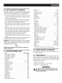
3.1 MAINTENANCESCHEDULE
Follow the calendar intervals. More frequent service is required
whenoperatingin adverseconditionsnotedbelow.
CheckOil Level
ChangeOil and OilFilter:!:
CleanSparkArrestor Screen
ServiceAir Filter
ReplaceSparkPlug
$
"k
At EachUse
*Every Season/Every100 Hours
**Every Season/Every100 Hours
**Every Season/Every200 Hours
EverySeason
Changeoil after first 30 hours of operationthenevery season.
Changeoil and oil filter every month when operatingunder heavyload or in
high temperatures.
Cleanmore often under dirty or dusty operating conditions. Replaceair filter
parts if very dirty.
3.2 PRODUCTSPECIFICATIONS
3.2.1 GENERATORSPEC/F/CATIONS
Model # ...................................................................... 005800, 005747
RatedMax.Power................................................................... 8.0 kW**
SurgePower................................................................................ 10 kW
RatedACVoltage...................................................................... 120/240
RatedMax AC Load
Current@ 240V............................................................. 33.3 Amps**
Current@ 120V............................................................. 66.7 Amps**
RatedFrequency.................................................... 60 Hz@ 3600 RPM
Phase................................................................................ SinglePhase
RatedDCVoltage...................................................................... 12 Volts
BatteryType.................................................................... 10 AH, 12VDC
Model # ...................................................................... 005797, 005798
RatedMax.Power................................................................... 7.0 kW**
SurgePower............................................................................. 8.75 kW
RatedACVoltage...................................................................... 120/240
RatedMax ACLoad
Current@ 240V............................................................. 29.2 Amps**
Current@ 120V............................................................. 58.3 Amps**
RatedFrequency.................................................... 60 Hz@ 3600 RPM
Phase................................................................................ SinglePhase
RatedDCVoltage...................................................................... 12 Volts
BatteryType.................................................................... 10 AH, 12VDC
Model# .................................................................................... 005796
RatedMax.Power................................................................... 6.5 kW**
SurgePower............................................................................. 8.13 kW
RatedACVoltage...................................................................... 120/240
RatedMax ACLoad
Current@ 240V............................................................. 27.1 Amps**
Current@ 120V............................................................. 54.2 Amps**
RatedFrequency.................................................... 60 Hz@ 3600 RPM
Phase................................................................................ SinglePhase
RatedDCVoltage...................................................................... 12 Volts
** Maximumwattageandcurrentaresubjectto,andlimitedby,suchfactors
asfuelBtucontent,ambienttemperature,altitude,enginecondition,etc..
Maximumpowerdecreasesabout3.5%foreach1,000feetabovesealevel;
andwillalsodecreaseabout1%foreach6° C(10° F)above16° C(60° F)
ambienttemperature.
3.2.2 ENGINESPEC/F/CATiONS
RatedHorsepower@ 3600 RPM.................................................... 14.5
Displacement............................................................................... 410cc
SparkPlugType................................... ChampionRC14YCor Equivalent
SparkPlug PartNo.................................................................... 0E7585
SparkPlug Gap............................................... 0.030 inch or (0.76 mm)
GasolineCapacity............................................................ 9 U.S.gallons
OilType.................................... SeeChart in "AddingEngineOil"Section
OilCapacity................................................ w/Filter Change= 1.5 Qts.
w/o FilterChange= 1.2 Qts.
Oil FilterPart No...................................................................... 070185B
RunTime/FuelConsumption-l/2 Load.. 10 Hours/ .73 gallonsper hour
Class IIEmissionCertified
3.2.3 EMISSIONS/NFORMATiON
The EnvironmentalProtection Agency (EPA) requires that this
generatorcomplywith exhaustandevaporativeemissionstandards.
This generatoris certified to meet the applicable EPAemission
levelson gasoline.Theemission control systemon this generator
consists ofthe following:
• FuelSystem • Air InductionSystem
Carburetor - IntakePipe/manifold
FuelTank!cap - AirFilter
FuelLines * IgnitionSystem
EvaporativeVentLines _ Sparkplug
ExhaustSystem - Ignitionmodule
ExhaustManifold • ExhaustSystem
Muffler _ ExhaustManifold
It is importantto perform the servicespecifiedin the Maintenance
Scheduleto ensurethatthe generatorcomplieswith the applicable
emissionstandardsfor the durationof its useful life. Additionally,
emissions critical maintenancemust be performed as scheduled
in orderfor the EmissionsWarrantyto be valid. Emissionscritical
maintenanceconsists of servicingthe air filter andspark plugsin
accordancewith the MaintenanceSchedule.Service and repairs
may be performedby any capablepersonor repairshop.
12

3.3 GENERALRECOIVIIVlENDATIONS
Thewarrantyof thegeneratordoes notcover itemsthat havebeen
subjectedto operator abuseor negligence.To receivefull value
from the warranty, the operator must maintain the generatoras
instructed inthis manual.
Some adjustmentswilt need to be made periodically to properly
maintainthegenerator.
All adjustmentsin the Maintenancesectionof this manualshould
be madeat leastonceeachseason.Followthe requirementsinthe
"MaintenanceSchedule".
NOTE:
Oncea yearreplacethesparkplugand replacetheairfilter.
A new spark plug and cleanair filter assure properfuel-air
mixture and helpthe enginerunbetter and lastlonger.
3.3.1 GENERATOR/V/A/NTENANCE
Generatormaintenanceconsistsof keepingthe unitcleanand dry.
Operateand storethe unit in a cleandry environmentwhereit will
not be exposedto excessivedust,dirt, moistureor any corrosive
vapors.Coolingair slotsin thegeneratormustnot becomeclogged
with snow, leaves,or anyotherforeign material.
Checkthe cleanlinessof the generatorfrequentlyand cleanwhen
dust, dirt, oil, moistureor otherforeign substancesarevisible on
its exteriorsurface.
,ACAUTION!
,iA Never insertany object or toolthroughthe air cooling
slots,evenif theengineis notrunning.
NOTE:
DONOTusea garden hosetocleangenerator. Water can
entertheengine fuel systemand causeproblems. In addition,
if water entersthegeneratorthroughcoolingair slots, some
water will be retainedin voidsandcrevicesof the rotor
and stator winding insulation. Wateranddirt builduponthe
generator internalwindings will eventuallydecreasethe
insulationresistanceofthesewindings.
3.3.2 TOCLEANTHEGENERATOR
• Usea dampcloth to wipe exteriorsurfaces clean.
• A soft, bristlebrushmay beusedto loosencakedon dirt, oil,etc.
• A vacuumcleanermay be usedto pick up loosedirt anddebris.
• Low pressure air (not to exceed 25 psi) may be used to
blow away dirt. Inspect cooling air slots and openingson the
generator.Theseopeningsmustbekeptcleanandunobstructed.
3.3.3 ENGINEMAINTENANCE
,ACAUTION!
,l_ When workingon thegenerator,alwaysdisconnect
negativecablefrombattery. Also disconnect sparkplug
wire from sparkplugand keepwire away fromspark
plug.
3.3.4 CHECKINGOILLEVEL
See the "BEFORESTARTINGTHE GENERATOR"section for
information on checking the oil level. The oil level should be
checkedbeforeeachuse,or at leasteveryeighthoursof operation.
Keepthe oil levelmaintained.
3.3.5 CHANGINGTHEOILANDOILFILTER
Changethe oil and filter after the first 30 hours of operation.
Changethe oil every 100 hours or every season thereafter. If
running this unit under dirty or dusty conditions, or in extremely
hotweather,changethe oil moreoften.
,l_ Not oil may causeburns. Allow engineto coolbefore
draining oil. Avoid prolongedor repeatedskin exposure
with usedoil. Thoroughlywashexposed areaswithsoap.
Use the following instructionsto changethe oil:
• Cleanareaaroundoil draincap.
• Removeoil draincapfrom thedrainhoseandoilfill plugto drain
oil completely intoa suitablecontainer.
• Whenoil hascompletelydrained,installoil draincapandtighten
securely.
• Place a suitable container beneath the oil filter and turn
filter counterclockwiseto remove. Discardaccording to local
regulations.
• Coat gasket of new filter with clean engine oil. Turn filter
clockwise until gasketcontacts lightly with filter adapter.Then
tightenan additional3/4 turn.
• Filloil sumpwith recommendedoil and replacethe oil fill plug.
(See"BeforeStartingthe Generator"for oil recommendations).
• Wipeup anyspilledoil.
• Disposeof usedoil at a propercollectioncenter.
3.3.6 REPLACINGTHESPARKPLUG
Use Champion RC14YCspark plug or equivalent.Replace the
plug once eachyear. This will help the engine start easier and
run better.
1. Stopthe engineand pull the spark plug wire off of the spark
plug.
2. Togain access,removethe four (4) socket head screws and
takeoff theside panel.
3. Cleanthe area aroundthe spark plug and remove it from the
cylinder head.
4. Set the spark plug's gap to .76 mm (0.030 in.). Install the
correctly gappedsparkplug intothe cylinderhead(Figure13).
5. Pushthe bootfirmly on the sparkplug and install sidepanel.
13

Figure 13 - Spark P/ug Gap
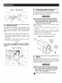
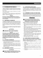
3.4 SERVICEAiRFILTER
Theenginewill not run properlyand may be damagedif using a
dirty air filter.Cleanor replacethe air filter paperfilter every 200
hours or once a year (Figure14). Cleanor replacemore often if
operating under dusty conditions. To clean or replacepaper air
filter:
* Removeairfilter cover andremove paperfilter (Figure14).
* Cleanpaperfilter by tapping it gently on a solid surface. If the
filter is too dirty, replaceit with a new one.Disposeof the old
filter properly.
* Cleanair filter cover.Nextinsert new paperfilter intothe base
of theair filter.Re-installair filter cover.
NOTE:
Toorder a new air filter, pleasecontactthe nearestauthorized
servicecenterat 1-888-GENERAC.Theair filter part number
is 073111.
Figure14- Air Filter
AIRFILTER
COVER
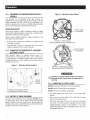
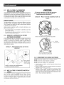
3.5 CLEANSPARKARRESTORSCREEN
The engine exhaustmuffler has a spark arrestorscreen. Inspect
andcleanthe screenat leastonceeachyear (Figure15). If unit is
usedregularly,inspectandcleanmore often.
&if using the generator on any forest=covered,
brush=covered or grass=covered unimproved
land, it must equipped with a spark arrestor.
The spark arrestor must be maintained in good
condition by the owner/operator.
Cleanandinspectthe sparkarrestorwhentheengineisat ambient
temperatureasfollows:
* Loosenthe clamp and removethe spark arrestor screenfrom
the muffler.
* Inspect screen and replace if torn, perforated or otherwise
damaged. DO NOT USEa defective screen. If screen is not
damaged,cleanitwith commercialsolvent.
* Replacethe sparkarrestor andsecurewith the clamp.
Figure 15 - Spark Arrestor Screen
ARRESTOR
SCREEN
CLAMP
SPARK
ARRESTOR
SCREEN
3.6 GENERAL
The generatorshould be started at leastonce every 30 days and
be allowedto run at least30 minutes. If this cannotbe done and
the unit must be storedfor morethan 30 days, usethefollowing
informationas a guideto prepareit for storage.
NEVER store engine with fuel in tank indoors
or in enclosed, poorly ventilated areas where
fumes may reach an open flame, spark or pilot
light as on a furnace, water heater, clothes
dryer or other gas appliance.
,_AIIow unit to cool entirely before storage.
14

3.7 LONGTERMSTORAGE
It is importantto preventgum depositsfrom forming in essential
fuel systemparts such asthe carburetor,fuel hoseor tank during
storage. To avoid engine problems, the fuel system should be
emptiedbeforestorageof 30 daysor longer,asfollows:
• Removeall gasolinefrom the fueltank.
,_ CAUTION!
,A Drainfuel intoapproved containeroutdoors,away from
openflame. Besureengine iscool.Donot smokein the
vicinityor lighta cigarette.
• Start and run engineuntil enginestopsfrom lack offuel.
• Allow the engineto cool, then drainoil from crankcase. Refill
with recommendedgrade.
• Removesparkplugandpour about1/2ounce(15 ml) of engine
oil into the cylinder.Cover spark plug hole with rag. Pull the
recoil starter a coupletimes to lubricatethe piston rings and
cylinder bore.
_,CAUTION!
,l_Avoid spray from spark plug hole when
cranking engine.
• Install and tighten spark plug. Do not connectthe spark plug
wire.
• Cleanthegeneratoroutersurfaces. Checkthat coolingair slots
and openingson generatorareopen and unobstructed.
• Storetheunit in a clean,dry place.
3.8 OTHERSTORAGETiPS
• Do notstore gasolinefrom oneseasonto another.
• Replaceanygasolinecanthat starts to rust. Rustand/ordirt in
the gasolinewill cause problems with the carburetor and fuel
system.
• If possible,storethe unitindoorsand coverit to giveprotection
from dust and dirt. Cover the unit with a suitable protective
coverthat doesnot retainmoisture.
• BE SURETO EMPTYTHE FUELTANK.If it is not practical
to empty the fuel tank and the unit is to be storedfor some
time, usea commerciallyavailablefuel stabilizeraddedto the
gasolineto increasethe lifeof thegasoline.
_,CAUTION!
,l_ NEVER cover the generator while engine and
exhaust area are warm.
4.1 BATTERYREPLACEMENT(XGT000E&XGS000E)
NOTE:
The batteryshippedwiththe generatorhas beenfully charged.
Abattery may losesomeof itschargewhennot in usefor
prolongedperiodsof time. ifthe batteryis unabletocrank
the engine, plugin the 12V chargerincludedin theaccessory
box (seethe Charginga Batterysection).RUNNINGTHE
GENERATORDOESNOTCHARGETHEBATTERY.
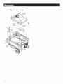
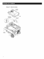
The battery shipped with the generatorhas been providedfully
charged.Toreplacethe battery(SeeFigure16):
Remove the side panel as shown. Remove the four bolts
securingthe fueltank.
Turnthe fuel valve on the control panelto the "OFF"position.
Pull the fuel tank backslightly and removethe fuel hosethat
runsfrom theengineto thefuelvalve.
,A CALITION!
,A Drainfuel intoapprovedcontaineroutdoors, away from
openflame. Be sureengineis cool.Donotsmokein the
vicinityor lighta cigarette.
• Disconnectthe recoveryhosefrom the rollovervalve.Pushthe
hosethroughthe grommet in the cornerof the fuel tank. This
will allowfor removalofthe fueltank.
• Pushthe fuel valvefrom thecontrol paneland removethefuel
tank.
• Removethe batterywire connections (blackwire first) andthe
batteryhold-downbracket.
• Replacethe battery,connectingthe REDwire to the POSITIVE
(+) terminalandthe BLACKwireto the NEGATIVE(-) terminal
NOTE:
Start all fourscrews on theside panel beforetighteningor fl
maynot bepossibletoget all the screwsin place.
15

Figure 16 - Battery Remova/
1_ FUELTANK
ASSEMBLY
It
ENGINE
STARTING
BATTERY
BRACKET
SIDE
PANEL
16

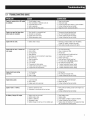
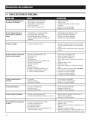
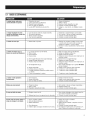
5.1TBOUBLESHOOTINGGUIDE
Engineis running,but noAC output
isavailable.
1. Circuitbreakeris open.
2. Poorconnectionor defectivecord set.
3. Connecteddeviceis bad.
4. Faultin generator.
5. GFCItrips the 20 Amp outlet.
1. Resetcircuit breaker.
2. Checkand repair.
3. Connectanotherdevicethat is in goodcondition.
4. ContactAuthorizedServiceFacility.
5. Repairthe "short" andresetthe GFCI.
Engineruns good but bogsdown 1. Short circuit in a connectedload. 1. Disconnectshorted electricalload.
whenloads are connected. 2. Generatoris overloaded. 2. See"Don't Overloadthe Generator".
3. Enginespeedis too slow. 3. ContactAuthorizedServiceFacility.
4. Shorted generatorcircuit. 4. ContactAuthorizedServiceFacility.
I I
Enginewill not crank. 1. Battery weakor dead. 1. Rechargeor replacebattery (see"NoBattery
ChargerDCoutput"at bottom of guide).
2. Start enginemanuallyusing recoil starter.
Enginewiil notstart; or starts and
runsrough.
1. Fuelshut-off is OFE 1.
2. Dirty airfilter. 2.
3. Outof gasoline. 3.
Stalegasoline. 4.
Sparkplug wire not connectedto sparkplug. 5.
Bad sparkplug. 6.
TurnFuelshut-off ON.
Cleanor replaceairfilter.
Fillfuel tank.
Drainfueltank andfill with freshfuel.
Connectwire to sparkplug.
Replacesparkplug.
,
5.
6.
7. Waterin gasoline.
8. Over-choking.
9. Low oil level.
10. Excessiverichfuel mixture.
11. Intakevalvestuck openor closed.
12. Enginehas lostcompression.
7. Drainfueltank;fill with fresh fuel.
8. Putchoke knobto No Chokeposition.
9. Fillcrankcaseto properlevel.
10. ContactAuthorizedService Facility.
11. ContactAuthorizedService Facility.
12. ContactAuthorizedService Facility.
Engineshuts downduring 1. Outof gasoline. 1. Fillfuel tank.
operation. 2. Low oil level. 2. Fillcrankcaseto properlevel.
3. Faultin engine. 3. ContactAuthorizedServiceFacility.
m u
Enginelacks power. 1. Loadis too high. 1. See"Don't Overloadthe Generator".
2. Dirty airfilter. 2. Replaceair filter.
3. Engineneedsto be serviced. 3. ContactAuthorizedServiceFacility.
Engine"hunts" or falters. 1. Chokeis openedtoo soon. 1. Movechoke to halfway positionuntil engineruns
2. Carburetoris runningtoo rich or too lean. smoothly.
2. ContactAuthorizedServiceFacility.
NoBatteryChargerDOoutput. 1. Battery posts arecorroded.
2. Batterycableis bad.
3. Batteryis defective.
4. Receptacleis bad.
5. BatteryChargerin-line fuse (1.5A)melted open.
1. Cleanbatteryposts.
2. Replacecable.
3. Checkbattery condition;replaceif defective.
4. ContactAuthorizedServiceFacility.
5. Replacefuse with identical 1.5A replacementfuse
only (locatedinsidecontrol panel).
1"7
Page is loading ...

U,S, EPA EMiSSiON CONTROL WARRANTY STATEMENT
YOUR WARRANTY RIGHTS AND OBLiGATiONS
TheUnited StatesEnvironmentalProtectionAgency (EPA)andGeneracPowerSystems,Inc. (Generac)arepleasedto explainthe EmissionControl
SystemWarranty(ECSWarranty) on yournew 2011 and laterequipment.New equipmentthat use smallspark-ignitedenginesmust bedesigned,built,
andequippedto meetstringentanti-smog standardsfor the federalgovernment.Generacwill warrantthe emission control systemon your equipment
for the periodof time listed belowprovidedthere has beenno abuse, neglect,unapprovedmodificationor impropermaintenanceofyour equipment.
Theemission control systemon this equipmentincludes all componentswhose failurewould increasethe emissionsof anyregulatedpollutant.These
componentsarelisted in the Emissions Information sectionofthis manual.
MANUFACTURER'S WARRANTY COVERAGE:
This ECSWarrantyis validfor two years,or for the sameperiod as specifiedin the GeneracLimitedWarranty,whicheveris longer. Forequipmentwith
hourmeters,the warranty period is a number of hours equalto halfthe UsefulLifeto whichthe equipmentis certified, or the warrantyperiod specified
abovein years,whicheveris less.TheUsefulLife can befound on the EmissionControlLabelon the engine.If, during suchwarranty period,any
emission-relatedpart on yourequipment isfound to be defectivein materialsor workmanship, repairs or replacementwill be performedby a Generac
AuthorizedWarrantyServiceDealer.
OWNER'S WARRANTY RESPONSiBiLiTiES:
Asthe equipmentowner,you areresponsiblefor the completion of all requiredmaintenanceas listed in your factory suppliedOwner'sManual.For
warranty purposes,Generacrecommendsthat you retainall receiptscovering maintenanceon your generator,but Generaccannotdeny warranty
solelydueto the lackof receipts.
Youshould beawarethat Generacmay deny anyand/or all warrantycoverageor responsibilityif your equipment,or apart!componentthereof,has
failed due to abuse,neglect, impropermaintenance,or unapprovedmodifications.
Youare responsible for contactingaGeoeracAuthorized Warranty Dealeras soonas a problemoccurs.Thewarranty repairsshouldbe
completed in a reasonable amount of time, not to exceed 30 days.
Warrantyservice can bearrangedby contacting eitheryour sellingdealeror aGeneracAuthorizedWarrantyServiceDealer.Tolocate the Generac
AuthorizedWarrantyServiceDealernearestyou, call ourtoll free numberbelow, oremail [email protected].
1-800-333-1322
IMPORTANTNOTE:This warranty statementexplainsyour rights and obligationsunder the EmissionControlSystemWarranty,which is providedto
you by Generacpursuantto federal law. Seealsothe "GeneracLimitedWarrantiesfor GeneracPowerSystems,Inc.," which is enclosedherewith on a
separatesheet,also providedto you byGenerac.Notethat this warranty shall not apply to any incidental,consequentialor indirect damagescaused
bydefects in materialsor workmanship orany delayin repairor replacementof the defectivepart(s). This warranty is in place of all other warranties,
expressedor implied.Specifically,Generacmakesno other warrantiesas to the merchantabilityor fitness for a particular purpose.Any implied
warrantieswhich areallowed by law, shallbe limited in durationto the terms of the expresswarranty providedherein.Somestates do not allow
limitationson how long an impliedwarrantylasts, sothe abovelimitation may not applyto you.
TheECSWarranty appliesonly to the emissioncontrol system of your newequipment.Boththe ECSWarrantyandthe GeneracWarrantydescribe
importantrights and obligationswith respectto your new engine.
Warrantyservice can beperformed onlyby a GeneracAuthorizedWarrantyServiceFacility.When requestingwarranty service,evidencemust be
presentedshowingthe dateofthe saleto the originalpurchaser/owner.
Ifyou haveany questionsregardingyour warranty rightsand responsibilities,you shouldcontact Generacatthe following address:
ATTENTION WARRANTY DEPARTMENT
GENERAC POWER SYSTEMS, INC.
P.O. BOX 297 * WHITEWATER, WI 53190
PartI of 2
PartNo. 0J3335 Rev.C 11/11
19

EMiSSiON CONTROL SYSTEM WARRANTY
EmissionControlSystemWarranty (ECSWarranty)for equipmentusing small spark-ignitedengines:
(a) Applicability: This warrantyshall applyto equipmentthat usessmall off-road engines.TheECSWarranty periodshallbeginon the datethe new
equipmentis purchasedby/deliveredto its original, end-usepurchaser/ownerandshall continue forthe lesserof:
(1) The periodof time specifiedin the GeneracLimitedWarrantyenclosedherewith,but not lessthan24 months,or
(2) Forenginesequippedwith hour meters,a numberof operatinghours equalto half ofthe engine'susefullife. The usefullife is specifiedon the
EmissionsControl Labelon the engine.
(b) GeneralEmissionsWarrantyCoverage:Generacwarrantsto the original,end-usepurchaser/ownerof the newengineor equipment andto each
subsequentpurchaser/ownerthat the ECSwhen installedwas:
(1) Designed,built and equippedso as to conform with all applicableregulations;and
(2) Freefrom defectsin materialsand workmanship which causethe failureof a warrantedpart at anytime duringthe ECSWarrantyPeriod.
(c) Thewarranty on emissions-relatedparts will be interpretedas follows:
(1) Any warrantedpart that is not scheduledfor replacementas requiredmaintenancein the Owner'sManualshall bewarrantedfor the ECS
WarrantyPeriod.If any such partfails during the ECSWarrantyPeriod, it shall be repairedor replacedby Generacaccordingto Subsection
(4) below. Any such part repairedor replacedunderthe EOSWarrantyshallbewarrantedforthe remainderof the ECSWarrantyPeriod.
(2) Any warrantedpart that is scheduledonlyfor regularinspection asspecifiedin the Owner'sManualshallbe warrantedfor the EOSWarranty
Period.Astatementin the Owner's Manualtothe effectof "repair or replace asnecessary"shall not reducethe ECSWarrantyPeriod.Any
such part repairedor replacedunderthe ECSWarrantyshallbewarrantedfor the remainderofthe ECSWarranty Period.
(3) Any warrantedpart that is scheduledfor replacementasrequired maintenancein the Owner'sManualshall be warrantedfor the periodof time
priorto first scheduledreplacementpointfor that part. Ifthe part fails prior to thefirst scheduledreplacement,the part shall berepairedor
replacedby Generacaccordingto Subsection(4) below.Any such emissions-relatedpart repairedor replacedunderthe ECSwarranty shall
bewarrantedfor the remainderof the periodprior to thefirst scheduledreplacementpointfor thatpart.
(4) Repairor replacementof anywarranted,emissions-relatedpart underthis ECSWarrantyshall beperformedat no chargetothe ownerat a
GeneracAuthorizedWarrantyServiceFacility.
(5) Notwithstandingthe provisions of subsection(4) above,warranty services or repairsmust beprovidedat GeneracAuthorizedService
Facilities.
(6) Whenthe engineis inspectedby a GeneracAuthorizedWarrantyServiceFacility,the purchaser/ownershall not beheld responsiblefor
diagnosticcosts if the repairis deemedwarrantable.
(7) Throughoutthe ECSWarrantyPeriod, Generacshall maintainasupply of warrantedemission-relatedparts sufficient to meetthe expected
demandfor such parts.
(8) Any Generacauthorizedand approvedemission-relatedreplacementparts may beusedin the performanceof any ECSWarrantymaintenance
or repairsandwill beprovidedwithout chargeto the purchaser/owner.Such useshall not reduceGenerac'sEOSWarrantyobligations.
(9) No modifications,other thanthose explicitlyapproved by Generac,may be madeto the generator.Unapprovedmodificationsvoid this ECS
Warrantyand shall be sufficientgroundfor disallowingan EOSWarrantyclaim.
(10) Generacshall not be heldliablehereunderfor failures of any non-authorizedreplacementparts, or failures of anyauthorizedparts causedby
the use of non-authorizedreplacementparts.
EMiSSiON RELATED PARTS MAY iNCLUDE THE FOLLOWING (iF EQUIPPED):
1) FUELMETERINGSYSTEM 3) IGNITIONSYSTEM
A. CARBURETORANDINTERNALPARTS A. SPARKPLUGS
B. FUELTANK/CAP B. IGNITIONCOILS/MODULE
C. FUELLINES 4) AIRINJECTIONSYSTEM
D. EVAPORATIVEVENTLINES A. PULSEAIRVALVE
E. REGULATOR(GASEOUSFUELS) 5) EXHAUSTSYSTEM
2) AIR INDUCTIONSYSTEM A. CATALYST
A. INTAKEMANIFOLD B. EXHAUSTMANIFOLD
B. AIR FILTER
Part2 of 2
20
PartNo. 0J3335 Rev.C 11/11
Page is loading ...
Page is loading ...
Page is loading ...
Page is loading ...
Page is loading ...
Page is loading ...
Page is loading ...
Page is loading ...
Page is loading ...
Page is loading ...
Page is loading ...
Page is loading ...
Page is loading ...
Page is loading ...
Page is loading ...
Page is loading ...
Page is loading ...
Page is loading ...
Page is loading ...
Page is loading ...
Page is loading ...
Page is loading ...
Page is loading ...
Page is loading ...
Page is loading ...
Page is loading ...
Page is loading ...
Page is loading ...
Page is loading ...
Page is loading ...
Page is loading ...
Page is loading ...
Page is loading ...
Page is loading ...
Page is loading ...
Page is loading ...
Page is loading ...
Page is loading ...
Page is loading ...
Page is loading ...
Page is loading ...
Page is loading ...
Page is loading ...
Page is loading ...
Page is loading ...
Page is loading ...
Page is loading ...
Page is loading ...
Page is loading ...
Page is loading ...
-
 1
1
-
 2
2
-
 3
3
-
 4
4
-
 5
5
-
 6
6
-
 7
7
-
 8
8
-
 9
9
-
 10
10
-
 11
11
-
 12
12
-
 13
13
-
 14
14
-
 15
15
-
 16
16
-
 17
17
-
 18
18
-
 19
19
-
 20
20
-
 21
21
-
 22
22
-
 23
23
-
 24
24
-
 25
25
-
 26
26
-
 27
27
-
 28
28
-
 29
29
-
 30
30
-
 31
31
-
 32
32
-
 33
33
-
 34
34
-
 35
35
-
 36
36
-
 37
37
-
 38
38
-
 39
39
-
 40
40
-
 41
41
-
 42
42
-
 43
43
-
 44
44
-
 45
45
-
 46
46
-
 47
47
-
 48
48
-
 49
49
-
 50
50
-
 51
51
-
 52
52
-
 53
53
-
 54
54
-
 55
55
-
 56
56
-
 57
57
-
 58
58
-
 59
59
-
 60
60
-
 61
61
-
 62
62
-
 63
63
-
 64
64
-
 65
65
-
 66
66
-
 67
67
-
 68
68
-
 69
69
-
 70
70
-
 71
71
-
 72
72


Generac 005747-1 Owner's manual
- Category
- Power generators
- Type
- Owner's manual
- This manual is also suitable for
Ask a question and I''ll find the answer in the document
Finding information in a document is now easier with AI
in other languages
Related papers
-
Generac 005778-0 Owner's manual
-
Generac XG8000E G0057473 User manual
-
-
-
-
-
-
-
-
Other documents
-
 AC Tool Supply XG8000 Owner's manual
-
Briggs & Stratton 030239 Owner's manual
-
-
Craftsman 580327360 Owner's manual
-
Craftsman 580675611 Owner's manual
-
-
-
Sears Portable Generator 005735-0 User manual
-
Franklin Chef FBC36OD Owner's manual
-
Amana AP095R User manual
