
Emerson Process Management
00375-0047-0001, rev F
Emerson Process Management
Asset Optimization Division
12001 Technology Drive
Eden Prairie, MN 55344 USA
www.fieldcommunicator.com
©2009, Emerson Process Management.
The contents of this publication are presented for
informational purposes only, and while every effort
has been made to ensure their accuracy, they are
not to be construed as warranties or guarantees,
express or implied, regarding the products or
services described herein or their use or applicability.
All sales are governed by our terms and conditions,
which are available on request. We reserve the right
to modify or improve the designs or specifications
of our products at any time without notice.
All rights reserved. The Emerson logo is a trademark
and service mark of Emerson Electric Co. All other
marks are the property of their respective owners.
Printed in USA/2-2009
USER’S
MANUAL
375 Field Communicator User
’
s Manual


USER’S MANUAL
February 2009
375 FIELD COMMUNICATOR
www.fieldcommunicator.com
375 FIELD COMMUNICATOR
© 2009 Emerson Process Management. All rights reserved.
The Emerson logo is a trademark and service mark of Emerson Electric Co.
AMS Suite is a registered trademark of Emerson Electric Co.
Rosemount and SMART FAMILY are registered trademarks of Rosemount Inc.
Windows is a registered trademark of Microsoft Corporation in the United States and
other countries.
IrDA is a registered trademark of the Infrared Data Association.
F
OUNDATION is a trademark of the Fieldbus Foundation.
HART is a registered trademark of the HART Communication Foundation.
WirelessHART is a trademark of the HART Communication Foundation.
Hitachi is a registered trademark of Hitachi America, Ltd.
All other marks are the property of their respective owners.
US and foreign patent numbers are pending.
NOTICE
Read this User’s Manual before working with the 375 Field Communicator. For
personal and system safety, and for optimum product performance, thoroughly
understand the contents before using or servicing this product.
For equipment service needs, contact the nearest product representative.


www.fieldcommunicator.com
USER’S MANUAL
February 2009
375 FIELD COMMUNICATOR
TABLE OF CONTENTS
SECTION 1
Introduction
Using this Manual. . . . . . . . . . . . . . . . . . . . . . . . . . . . . . . . . . . . . . . . . 1-1
SECTION 2
Learning the Basics
Overview . . . . . . . . . . . . . . . . . . . . . . . . . . . . . . . . . . . . . . . . . . . . . . . . 2-1
Safety Messages. . . . . . . . . . . . . . . . . . . . . . . . . . . . . . . . . . . . . . . . . . 2-1
Product Overview and Precautions . . . . . . . . . . . . . . . . . . . . . . . . . . 2-2
375 Field Communicator Components . . . . . . . . . . . . . . . . . . . . . . . 2-2
Working in an Intrinsically Safe (IS) Area . . . . . . . . . . . . . . . . . . . . . 2-3
Battery and Power Supply/Charger Overview . . . . . . . . . . . . . . . . . . 2-4
Guidelines and Precautions . . . . . . . . . . . . . . . . . . . . . . . . . . . . . . . 2-4
Check the Charge Remaining. . . . . . . . . . . . . . . . . . . . . . . . . . . . . . 2-5
Charge the Battery . . . . . . . . . . . . . . . . . . . . . . . . . . . . . . . . . . . . . . 2-5
Maintaining the Battery Life and Performance . . . . . . . . . . . . . . . . . 2-7
Installing the System Card and the Battery . . . . . . . . . . . . . . . . . . . . 2-8
Removing the Battery and the System Card . . . . . . . . . . . . . . . . . . . 2-9
Starting Up and Shutting Down. . . . . . . . . . . . . . . . . . . . . . . . . . . . . . 2-9
Starting the 375 Field Communicator . . . . . . . . . . . . . . . . . . . . . . . . 2-9
Entering Stand-By. . . . . . . . . . . . . . . . . . . . . . . . . . . . . . . . . . . . . . 2-10
Shutting Down the 375 Field Communicator. . . . . . . . . . . . . . . . . . 2-10
Basic Features and Functions. . . . . . . . . . . . . . . . . . . . . . . . . . . . . . 2-11
Using the Keypad . . . . . . . . . . . . . . . . . . . . . . . . . . . . . . . . . . . . . . 2-12
Using the Touch Screen . . . . . . . . . . . . . . . . . . . . . . . . . . . . . . . . . 2-14
The 375 Main Menu. . . . . . . . . . . . . . . . . . . . . . . . . . . . . . . . . . . . . . . 2-15
Starting the HART Application . . . . . . . . . . . . . . . . . . . . . . . . . . . . 2-15
Starting the Fieldbus Application. . . . . . . . . . . . . . . . . . . . . . . . . . . 2-15
Running the Settings Menu. . . . . . . . . . . . . . . . . . . . . . . . . . . . . . . 2-15
Communicating with a PC. . . . . . . . . . . . . . . . . . . . . . . . . . . . . . . . 2-21
Using ScratchPad . . . . . . . . . . . . . . . . . . . . . . . . . . . . . . . . . . . . . . 2-24
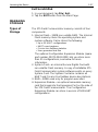
Managing Storage. . . . . . . . . . . . . . . . . . . . . . . . . . . . . . . . . . . . . . . . 2-27
Types of Storage. . . . . . . . . . . . . . . . . . . . . . . . . . . . . . . . . . . . . . . 2-27

Table of Contents
TOC-2
Free Memory on a System Card . . . . . . . . . . . . . . . . . . . . . . . . . . 2-28
Maintenance . . . . . . . . . . . . . . . . . . . . . . . . . . . . . . . . . . . . . . . . . . . . 2-28
Running a Self Test . . . . . . . . . . . . . . . . . . . . . . . . . . . . . . . . . . . . 2-28
Calibrating . . . . . . . . . . . . . . . . . . . . . . . . . . . . . . . . . . . . . . . . . . . 2-29
Waste Disposal. . . . . . . . . . . . . . . . . . . . . . . . . . . . . . . . . . . . . . . . . . 2-29
Hazardous Substances . . . . . . . . . . . . . . . . . . . . . . . . . . . . . . . . . . . 2-29
SECTION 3
HART Functionality
Overview. . . . . . . . . . . . . . . . . . . . . . . . . . . . . . . . . . . . . . . . . . . . . . . . 3-1
Safety Messages . . . . . . . . . . . . . . . . . . . . . . . . . . . . . . . . . . . . . . . . . 3-1
Basic Features and Functions . . . . . . . . . . . . . . . . . . . . . . . . . . . . . . 3-2
Using a Fast Key Sequence . . . . . . . . . . . . . . . . . . . . . . . . . . . . . . . . 3-2
Starting the HART Application . . . . . . . . . . . . . . . . . . . . . . . . . . . . . . 3-2
Working Offline . . . . . . . . . . . . . . . . . . . . . . . . . . . . . . . . . . . . . . . . . . 3-3
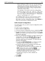
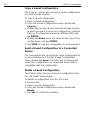
Creating New Configurations . . . . . . . . . . . . . . . . . . . . . . . . . . . . . . 3-3
Opening Saved Configurations . . . . . . . . . . . . . . . . . . . . . . . . . . . . 3-4
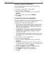
Working Online. . . . . . . . . . . . . . . . . . . . . . . . . . . . . . . . . . . . . . . . . . . 3-8
Connecting to a HART Loop . . . . . . . . . . . . . . . . . . . . . . . . . . . . . . 3-8
Displaying the Online Menu . . . . . . . . . . . . . . . . . . . . . . . . . . . . . . 3-11
Saving an Online Device Configuration . . . . . . . . . . . . . . . . . . . . . 3-12
Displaying the Device Setup Submenu . . . . . . . . . . . . . . . . . . . . . 3-12
Displaying Graphics . . . . . . . . . . . . . . . . . . . . . . . . . . . . . . . . . . . . 3-14
Using Hot Keys. . . . . . . . . . . . . . . . . . . . . . . . . . . . . . . . . . . . . . . . . . 3-15
Setting up Hot Key Options . . . . . . . . . . . . . . . . . . . . . . . . . . . . . . 3-15
Executing a Hot Key Option. . . . . . . . . . . . . . . . . . . . . . . . . . . . . . 3-16
Removing a Hot Key Option. . . . . . . . . . . . . . . . . . . . . . . . . . . . . . 3-16
Removing all Hot Key Options . . . . . . . . . . . . . . . . . . . . . . . . . . . . 3-16
Configuring the HART Application. . . . . . . . . . . . . . . . . . . . . . . . . . 3-17
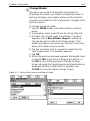
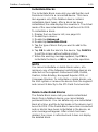
Changing the HART Polling Option . . . . . . . . . . . . . . . . . . . . . . . . 3-17
Changing Ignored Status Messages . . . . . . . . . . . . . . . . . . . . . . . 3-19
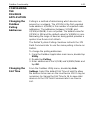
Changing the Menu Title . . . . . . . . . . . . . . . . . . . . . . . . . . . . . . . . 3-19
Storage Cleanup . . . . . . . . . . . . . . . . . . . . . . . . . . . . . . . . . . . . . . 3-20
Viewing Available Device Descriptions . . . . . . . . . . . . . . . . . . . . . 3-20
Simulating an Online Connection to a HART Device. . . . . . . . . . . 3-21
Running HART Diagnostics . . . . . . . . . . . . . . . . . . . . . . . . . . . . . . . 3-22
DC Voltage Measurement (HART Terminals) . . . . . . . . . . . . . . . . 3-22
Disconnecting from a HART Device. . . . . . . . . . . . . . . . . . . . . . . . . 3-22

Table of Contents
TOC-3
SECTION 4
Fieldbus Functionality
Overview . . . . . . . . . . . . . . . . . . . . . . . . . . . . . . . . . . . . . . . . . . . . . . . . 4-1
Safety Messages. . . . . . . . . . . . . . . . . . . . . . . . . . . . . . . . . . . . . . . . . . 4-1
Basic Features and Functions. . . . . . . . . . . . . . . . . . . . . . . . . . . . . . . 4-2
Link Active Scheduler (LAS) . . . . . . . . . . . . . . . . . . . . . . . . . . . . . . . 4-2
LAS Hierarchy. . . . . . . . . . . . . . . . . . . . . . . . . . . . . . . . . . . . . . . . . . 4-3
Device Interoperability. . . . . . . . . . . . . . . . . . . . . . . . . . . . . . . . . . . . 4-3
ST_REV . . . . . . . . . . . . . . . . . . . . . . . . . . . . . . . . . . . . . . . . . . . . . . 4-3
Starting the Fieldbus Application . . . . . . . . . . . . . . . . . . . . . . . . . . . . 4-4
Working Online . . . . . . . . . . . . . . . . . . . . . . . . . . . . . . . . . . . . . . . . . . . 4-5
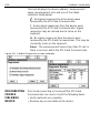
Connecting to a Fieldbus Segment. . . . . . . . . . . . . . . . . . . . . . . . . . 4-5
Displaying the Live Device List . . . . . . . . . . . . . . . . . . . . . . . . . . . . . 4-9
Displaying the Block List. . . . . . . . . . . . . . . . . . . . . . . . . . . . . . . . . 4-10
Displaying a device menu. . . . . . . . . . . . . . . . . . . . . . . . . . . . . . . . 4-10
Modes . . . . . . . . . . . . . . . . . . . . . . . . . . . . . . . . . . . . . . . . . . . . . . . 4-11
Working with Device Blocks . . . . . . . . . . . . . . . . . . . . . . . . . . . . . . 4-14
Displaying Graphics . . . . . . . . . . . . . . . . . . . . . . . . . . . . . . . . . . . . 4-20
Configuring the Fieldbus Application. . . . . . . . . . . . . . . . . . . . . . . . 4-21
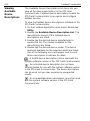
Changing the Fieldbus Polling Addresses . . . . . . . . . . . . . . . . . . . 4-21
Changing the Slot Time. . . . . . . . . . . . . . . . . . . . . . . . . . . . . . . . . . 4-21
Viewing Available Device Descriptions . . . . . . . . . . . . . . . . . . . . . . 4-22
Running Fieldbus Diagnostics . . . . . . . . . . . . . . . . . . . . . . . . . . . . . 4-23
DC Voltage and Noise Level Measurement . . . . . . . . . . . . . . . . . . 4-23
Signal Level Measurement . . . . . . . . . . . . . . . . . . . . . . . . . . . . . . . 4-23
Disconnecting from a Fieldbus Device. . . . . . . . . . . . . . . . . . . . . . . 4-24
SECTION 5
Troubleshooting
Overview . . . . . . . . . . . . . . . . . . . . . . . . . . . . . . . . . . . . . . . . . . . . . . . . 5-1
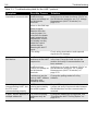
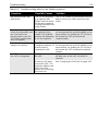
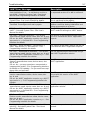
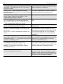
Troubleshooting Suggestions . . . . . . . . . . . . . . . . . . . . . . . . . . . . . . 5-1
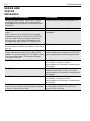
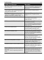
Error and Status Messages . . . . . . . . . . . . . . . . . . . . . . . . . . . . . . . . . 5-6
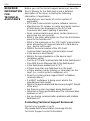
Required Information for Technical Assistance . . . . . . . . . . . . . . . 5-10
APPENDIX A
Reference Information
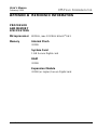
Processor and Memory Specifications. . . . . . . . . . . . . . . . . . . . . . . .A-1
Microprocessor . . . . . . . . . . . . . . . . . . . . . . . . . . . . . . . . . . . . . . . . .A-1
Memory. . . . . . . . . . . . . . . . . . . . . . . . . . . . . . . . . . . . . . . . . . . . . . .A-1
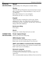
Physical Specifications . . . . . . . . . . . . . . . . . . . . . . . . . . . . . . . . . . . .A-2
Connection Specifications. . . . . . . . . . . . . . . . . . . . . . . . . . . . . . . . . .A-2

Table of Contents
TOC-4
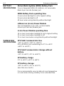
Power Supply/Charger Specifications. . . . . . . . . . . . . . . . . . . . . . . . A-3
Battery Specifications . . . . . . . . . . . . . . . . . . . . . . . . . . . . . . . . . . . . . A-4
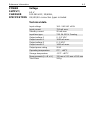
Temperature Specifications . . . . . . . . . . . . . . . . . . . . . . . . . . . . . . . . A-4
Order Information. . . . . . . . . . . . . . . . . . . . . . . . . . . . . . . . . . . . . . . . . A-5
Spare Parts List . . . . . . . . . . . . . . . . . . . . . . . . . . . . . . . . . . . . . . . . . . A-7
APPENDIX B
Product Certifications
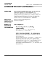
Overview. . . . . . . . . . . . . . . . . . . . . . . . . . . . . . . . . . . . . . . . . . . . . . . . B-1
Approved Manufacturing Locations. . . . . . . . . . . . . . . . . . . . . . . . . . B-1
European Directive Information . . . . . . . . . . . . . . . . . . . . . . . . . . . . . B-1
Hazardous Locations Certifications (KL option only) . . . . . . . . . . . B-2
International Certifications . . . . . . . . . . . . . . . . . . . . . . . . . . . . . . . . B-2
North American Certifications. . . . . . . . . . . . . . . . . . . . . . . . . . . . . . B-2
European Certifications . . . . . . . . . . . . . . . . . . . . . . . . . . . . . . . . . . B-3
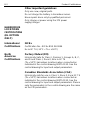
Power Supply/Charger Certification. . . . . . . . . . . . . . . . . . . . . . . . . . B-4
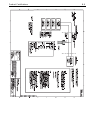
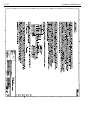
Label Drawings. . . . . . . . . . . . . . . . . . . . . . . . . . . . . . . . . . . . . . . . . . . B-4
Approval Drawings . . . . . . . . . . . . . . . . . . . . . . . . . . . . . . . . . . . . . . . B-7
APPENDIX C
Graphics Information
Overview. . . . . . . . . . . . . . . . . . . . . . . . . . . . . . . . . . . . . . . . . . . . . . . . C-1
Screen Layout . . . . . . . . . . . . . . . . . . . . . . . . . . . . . . . . . . . . . . . . . . . C-2
Buttons . . . . . . . . . . . . . . . . . . . . . . . . . . . . . . . . . . . . . . . . . . . . . . . . . C-3
Graphics Options. . . . . . . . . . . . . . . . . . . . . . . . . . . . . . . . . . . . . . . . . C-4
Images . . . . . . . . . . . . . . . . . . . . . . . . . . . . . . . . . . . . . . . . . . . . . . . C-4
Charts. . . . . . . . . . . . . . . . . . . . . . . . . . . . . . . . . . . . . . . . . . . . . . . . C-5
Graphs . . . . . . . . . . . . . . . . . . . . . . . . . . . . . . . . . . . . . . . . . . . . . . C-10
Glossary. . . . . . . . . . . . . . . . . . . . . . . . . . . . . . . . . . . . . . G-i
Index . . . . . . . . . . . . . . . . . . . . . . . . . . . . . . . . . . . . . I-1

www.fieldcommunicator.com
USER’S MANUAL
February 2009
375 FIELD COMMUNICATOR
SECTION 1INTRODUCTION
USING THIS
MANUAL
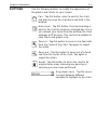
The sections in this manual provide the following
information on the 375 Field Communicator.
Section 2: Learning the Basics contains information on
settings, types of storage, IrDA
®
communication, card
readers, ScratchPad, maintenance, and managing files
and storage.
Section 3: HART Functionality contains information on
starting and configuring the HART
®
Application,
establishing communication with connected HART
devices, and viewing the menus.
Section 4: Fieldbus Functionality contains information
on starting and configuring the Fieldbus Application,
establishing communication with connected fieldbus
devices, and viewing the menus.
Section 5: Troubleshooting provides solutions to the
most common 375 Field Communicator operating
problems.
Appendix A: Reference Information provides physical,
functional, and performance specifications.
Appendix B: Product Certifications contains
Hazardous Location Certifications, European directive
information, and approval drawings.
Appendix C: Graphics Information contains an
overview of the Graphics functionality and screen
options in the 375 Field Communicator.

Introduction
1-2

www.fieldcommunicator.com
USER’S MANUAL
February 2009
375 FIELD COMMUNICATOR
SECTION 2LEARNING THE BASICS
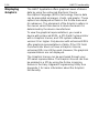
OVERVIEW This section provides instructions on basic features and
functions of the 375 Field Communicator. It also provides
information on starting, entering stand-by, shutting down,
configuring, and maintaining the 375 Field
Communicator. The functionality described in this
section is based on system software version 2.5.
SAFETY
MESSAGES
Procedures and instructions in this section may require
special precautions to ensure the safety of the personnel
performing the operation. Information that raises
potential safety issues is indicated by a warning symbol
( ). Refer to the following safety messages before
performing an operation preceded by this symbol. See
the Troubleshooting section for more warning messages.
IMPORTANT NOTICE
Ensure the battery and the 375 Field Communicator are properly aligned during assembly to
prevent damage to the connector pins.
IMPORTANT NOTICE
Do not pull up on the battery because this can damage the connector pins. The System Card
must be inserted or removed by applying gentle pressure in line with the axis of the System Card
and the System Port. Do not pull up or press down on the System Card because this can
damage the card or the communicator and void the warranty.
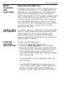
WARNING
A Re-Flash operation reinstalls the firmware and software from the System Card. This should
only be performed under the direction of Technical Support personnel.

Learning the Basics
2-2
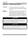
PRODUCT
OVERVIEW
AND
PRECAUTIONS
The 375 Field Communicator supports HART and
FOUNDATION fieldbus devices, letting you configure or
troubleshoot in the field. When using the 375 Field
Communicator, follow all standards and procedures
applicable to the location. Failure to comply may result in
equipment damage and/or personal injury. Be sure to
understand and comply with the following items:
375 Field
Communicator
Components
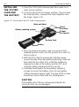
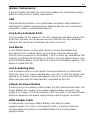
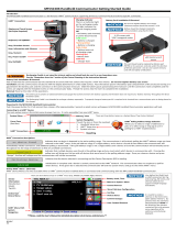
• The 375 Field Communicator includes an FSTN type
LCD with touch-screen display, a Nickel-Metal
Hydride (NiMH) Battery Pack or Lithium Ion (Li-Ion)
Power Module, an SH3 processor, memory
components, and integral communication and
measurement circuitry.
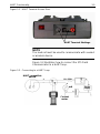
• Three terminals for the lead set are on the top of the
375 Field Communicator. The lead set and terminals
let you connect the 375 Field Communicator to a
device. Each red terminal is a positive connection for
its protocol, while the black terminal is a common
terminal shared by both protocols. An access door
ensures only one pair of terminals is exposed at any
one time. Several markings indicate which pair of
terminals is for which protocol.
• The infrared port and card reader let the 375 Field
Communicator or its System Card interface with a PC.
• Use the keypad or touch screen to enter data into the
375 Field Communicator.
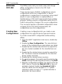
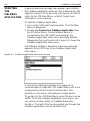
WARNING
Using Windows Explorer and a card reader to transfer files between the System Card and a PC
can corrupt the System Card. This operation should only be performed under the direction of
Technical Support personnel.
WARNING
The touch screen should be contacted by blunt items only, preferably the stylus included with the
375 Field Communicator. Using sharp instruments, such as screwdrivers, can cause failure of
the touch-screen display and void the warranty. Repair of the touch screen requires replacement
of the entire 375 Field Communicator display assembly, which is possible only at an authorized
service center.

Learning the Basics
2-3
• An Expansion Module, labeled Expansion Module, is
a removable memory card that snaps into the
Expansion Port.
• Only the Expansion Module or Expansion Port Plug
should be inserted into the Expansion Port. System
Cards/Secure Digital cards or other objects must not
be put into the Expansion Port. Failure to comply will
void the IS approval and the warranty.
• The System Card used in the System Port must be
supplied by the 375 Field Communicator
manufacturer. Failure to comply will void the IS
approval and the warranty.
Working in an
Intrinsically
Safe (IS) Area
• An IS-approved 375 Field Communicator can be used
in Zone 0 (FM and CSA only), Zone 1, or Zone 2,
Division 1 and Division 2 locations (KL option only).
• An IS-approved 375 Field Communicator may be
connected to loops or segments that are attached to
equipment located in Zone 0, Zone 1, Zone 2, Zone
20, Zone 21, Zone 22, Division 1 and Division 2 (KL
option only).
• The battery can be installed or removed in an
Intrinsically Safe area; however, it cannot be charged.
• The Expansion Module can be removed or installed in
a hazardous area.
• The Expansion Module can be installed in an
Intrinsically Safe area while the 375 Field
Communicator is still running.

Learning the Basics
2-4
BATTERY AND
POWER
SUPPLY/
CHARGER
OVERVIEW
The 375 Field Communicator supports two types of
batteries: the NiMH Battery Pack and the Li-Ion Power
Module. The NiMH Battery Pack has a black, 4-pin
power supply/charger connector and the Li-Ion Power
Module has a green, 6-pin connector. See Figure 2-3 on
page 2-11 for the location of the connector. The label on
the back of the battery also identifies the type.
NOTE
The term “battery” is used to describe functionality
common to both types of supported batteries. Any
differences are noted.
Guidelines and
Precautions
Before using the battery or power supply/charger
(00375-0003-0005), understand and follow the
guidelines below:
• When transporting a Li-Ion Power Module, follow all
applicable regulations.
• Use the power supply/charger with the 375 Field
Communicator only. Use only the supported power
supply/charger to charge the battery. Failure to
comply may permanently damage your 375 Field
Communicator and will void the IS approval and the
warranty.
• Protect the battery and power supply/charger from
moisture.
• Do not cover the battery or power supply/charger,
subject it to direct sunlight, or place it on or next to
heat-sensitive materials.
• Do not open or modify the battery or power
supply/charger. There are no user-serviceable
components or safety elements inside. Opening or
modifying them will void the warranty.

Learning the Basics
2-5
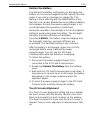
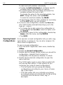
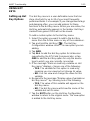
Check the
Charge
Remaining
Use the Power Status option in the Settings menu or the
lights on the battery to view the remaining charge. See
“Power Status” on page 2-18 for details.
To check the remaining charge from the lights on the
battery:
1. Remove the battery if it is connected to the 375 Field
Communicator. See “Removing the Battery and the
System Card” on page 2-9 for the procedure.
2. Turn the battery over, and press the charge indicator
button located on the lower left side. The lights
illuminate based on the amount of charge remaining.
Each light represents 20 percent of the charge
remaining. The battery is fully charged when all of the
lights are illuminated.
Charge the
Battery
CAUTION
The previous 4-pin power supply/charger is incompatible
with the 6-pin Li-Ion Power Module.
Prior to first portable use, fully charge the battery. The
battery can be charged separately or while attached to
the 375 Field Communicator. The 375 is fully operable
when the battery is recharging. The power
supply/charger can remain connected after the battery is
fully charged. An overcharge condition will not occur.
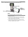
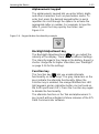
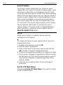
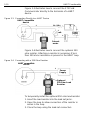
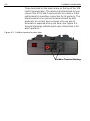
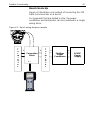
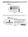
The power supply/charger is compatible with both types
of batteries. However, the NiMH Adapter Cable must be
used with the power supply/charger to charge the NiMH
Battery Pack. See Figure 2-1. The connector on the
power supply/charger is green to match the appropriate
connector on the Li-Ion Power Module or the NiMH
Adapter Cable.
The lights on the power supply/charger are amber when
charging, amber and green when the charge level is very
low, green when charging completes, and red when
charging cannot occur.

Learning the Basics
2-6
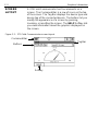
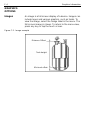
Figure 2-1. NiMH Adapter Cable used to charge the NiMH Battery Pack
NOTE
Do not charge the battery in hazardous areas.
To charge the battery:
1. Plug the power supply/charger into a power outlet.
2. Ensure the connectors match before connecting the
power supply/charger to the battery.
3. Plug the power supply/charger connector into the
battery. The battery is fully charged when the light on
the power supply/charger is green.
NiMH Adapter Cable
Lights
Power supply/charger
Green
connector on
the power
supply/charger

Learning the Basics
2-7
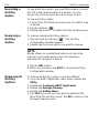
Maintaining
the Battery
Life and
Performance
To maintain the battery life and performance, understand
and follow the guidelines below:
Li-Ion Power Modules
• Recharge the Power Module frequently, preferably
after each use or at night. It is recommended to limit
the number of full discharge and recharge cycles.
• Frequent use at high temperatures can reduce
performance.
• Use a dry location at or near room temperature when
storing the Power Module for an extended time.
Prolonged storage at higher temperatures can reduce
performance.
• Ensure the remaining charge level is at or near
mid-capacity when storing for an extended time. The
remaining charge will slowly drain during storage.
Periodically charge the Power Module to ensure the
remaining charge does not drain to low levels.
NiMH Battery Packs
• Recharge the Battery Pack when it is nearly
discharged. NiMH Battery Packs benefit from full
discharge and recharge cycles.
• Use a dry, cool location when storing the Battery Pack
for an extended time.
• Ensure the remaining charge level is nearly full when
storing the Battery Pack. The remaining charge will
slowly drain during storage. Periodically charge the
Battery Pack to ensure the remaining charge does not
drain to low levels.

Learning the Basics
2-8
INSTALLING
THE SYSTEM
CARD AND
THE BATTERY
1. Place the 375 Field Communicator face down on a
level, secure surface.
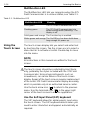
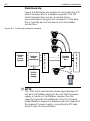
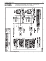
2. Lock the stand into the hanger position. (To pivot past
the stand position, squeeze the stand together near
the hinge, Figure 2-2.)
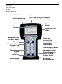
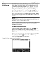
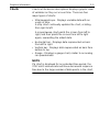
Figure 2-2. Back side of the 375 Field Communicator
3. With the battery removed, slide the System Card
(labeled System Card), into the System Port until it is
firmly in place.
4. With the 375 Field Communicator still face down,
ensure the tops of the two battery retaining screws are
flush with the top of the 375. Install the battery by
aligning the sides of the battery and the 375, and
carefully sliding it forward until it is secure.
5. Carefully hand tighten the two battery retaining
screws to secure the battery. (Do not over tighten,
0.5Nm maximum torque load.) The tops of the screws
should be close to flush with the stand groove.
CAUTION
If the battery and 375 are not properly aligned, the
connector pins can be damaged.
Battery retaining screws
Battery
System Card
Stand
assembly
Main unit label
IS label
(KL Option)

Learning the Basics
2-9
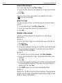
REMOVING
THE BATTERY
AND THE
SYSTEM
CARD
To remove the battery and System Card:
1. Place the 375 Field Communicator face down on a
level, secure surface.
2. Loosen the battery retaining screws until the top of
each screw is flush with the top of the 375 Field
Communicator.
3. Slide the battery off the 375. Do not pull the battery up
because this can damage the connector pins.
4. Grasp the System Card and slide it straight out of the
375. Do not pull the System Card up because this can
damage the card or the System Port.
STARTING UP
AND
SHUTTING
DOWN
Prior to using the 375 Field Communicator without the
power supply/charger, fully charge the battery. See
“Battery and Power Supply/ Charger Overview” on
page 2-4 for details on charging the battery.
Before operating the 375 Field Communicator, ensure:
• The 375 Field Communicator is not damaged.
• The battery is fully seated.
• All screws are sufficiently tightened.
• An Expansion Module or Expansion Port Plug is in
place.
• The Communication Terminal recess is free of dirt and
debris.
Starting the
375 Field
Communicator
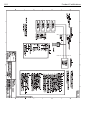
Press and hold the On/Off key until the multifunction
LED flashes (approximately two seconds). See
Figure 2-3 for the location of the On/Off key.
During start-up, the 375 Field Communicator
automatically checks for any software upgrades
available on the System Card.
You are notified if any
upgrade is required.
After starting the 375 Field Communicator, you can do
the following from the 375 Main Menu:
• Launch the HART or F
OUNDATION Fieldbus
Applications (if licensed)
• Configure and view settings
• Enter Listen For PC mode
• Launch ScratchPad

Learning the Basics
2-10
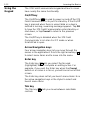
Entering
Stand-By
The 375 Field Communicator can be put into stand-by,
which turns off the display and certain areas within the
375 Field Communicator. Use this option to save power
or to reduce the boot-up time if you are using the 375
Field Communicator intermittently.
You can put the 375 Field Communicator in stand-by
when the HART Application or the Fieldbus Application
is running. If you are working online with a device when
stand-by is entered, the application main menu is
displayed when the 375 Field Communicator returns
from stand-by. Otherwise, the 375 Field Communicator
displays the last open screen.
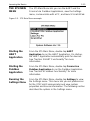
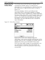
To enter stand-by, press the On/Off key. From the Power
Switch dialog box, tap Stand by and tap OK or press the
Enter key. Tap Cancel to close the dialog box and return
to the application. The multifunction LED will slowly flash
a green light when the 375 Field Communicator is in
stand-by. To leave stand-by, press the On/Off key.
The 375 Field Communicator also enters stand-by if the
stand-by timer has expired. See “Power Status” on
page 2-18 for more information.
Shutting Down
the 375 Field
Communicator
To shut down the 375 Field Communicator, press the
On/Off key. From the Power Switch dialog box, tap Shut
down and tap OK or press the Enter key. Tap Cancel to
close the dialog box and return to the application.
You can also shut down the 375 Field Communicator by
simultaneously pressing the Backlight Adjustment key
and the Function key until the display turns off. The shut
down is accomplished in the hardware (similar to
removing the power to a PC using a switch). This is not
the recommended way of shutting off the 375 Field
Communicator.
The 375 Field Communicator shuts down if the auto-off
timer has expired. See “Power Status” on page 2-18 for
more information.
Page is loading ...
Page is loading ...
Page is loading ...
Page is loading ...
Page is loading ...
Page is loading ...
Page is loading ...
Page is loading ...
Page is loading ...
Page is loading ...
Page is loading ...
Page is loading ...
Page is loading ...
Page is loading ...
Page is loading ...
Page is loading ...
Page is loading ...
Page is loading ...
Page is loading ...
Page is loading ...
Page is loading ...
Page is loading ...
Page is loading ...
Page is loading ...
Page is loading ...
Page is loading ...
Page is loading ...
Page is loading ...
Page is loading ...
Page is loading ...
Page is loading ...
Page is loading ...
Page is loading ...
Page is loading ...
Page is loading ...
Page is loading ...
Page is loading ...
Page is loading ...
Page is loading ...
Page is loading ...
Page is loading ...
Page is loading ...
Page is loading ...
Page is loading ...
Page is loading ...
Page is loading ...
Page is loading ...
Page is loading ...
Page is loading ...
Page is loading ...
Page is loading ...
Page is loading ...
Page is loading ...
Page is loading ...
Page is loading ...
Page is loading ...
Page is loading ...
Page is loading ...
Page is loading ...
Page is loading ...
Page is loading ...
Page is loading ...
Page is loading ...
Page is loading ...
Page is loading ...
Page is loading ...
Page is loading ...
Page is loading ...
Page is loading ...
Page is loading ...
Page is loading ...
Page is loading ...
Page is loading ...
Page is loading ...
Page is loading ...
Page is loading ...
Page is loading ...
Page is loading ...
Page is loading ...
Page is loading ...
Page is loading ...
Page is loading ...
Page is loading ...
Page is loading ...
Page is loading ...
Page is loading ...
Page is loading ...
Page is loading ...
Page is loading ...
Page is loading ...
Page is loading ...
Page is loading ...
Page is loading ...
Page is loading ...
Page is loading ...
Page is loading ...
Page is loading ...
Page is loading ...
Page is loading ...
Page is loading ...
Page is loading ...
Page is loading ...
Page is loading ...
Page is loading ...
Page is loading ...
Page is loading ...
Page is loading ...
Page is loading ...
Page is loading ...
Page is loading ...
Page is loading ...
Page is loading ...
Page is loading ...
Page is loading ...
Page is loading ...
Page is loading ...
Page is loading ...
Page is loading ...
Page is loading ...
Page is loading ...
-
 1
1
-
 2
2
-
 3
3
-
 4
4
-
 5
5
-
 6
6
-
 7
7
-
 8
8
-
 9
9
-
 10
10
-
 11
11
-
 12
12
-
 13
13
-
 14
14
-
 15
15
-
 16
16
-
 17
17
-
 18
18
-
 19
19
-
 20
20
-
 21
21
-
 22
22
-
 23
23
-
 24
24
-
 25
25
-
 26
26
-
 27
27
-
 28
28
-
 29
29
-
 30
30
-
 31
31
-
 32
32
-
 33
33
-
 34
34
-
 35
35
-
 36
36
-
 37
37
-
 38
38
-
 39
39
-
 40
40
-
 41
41
-
 42
42
-
 43
43
-
 44
44
-
 45
45
-
 46
46
-
 47
47
-
 48
48
-
 49
49
-
 50
50
-
 51
51
-
 52
52
-
 53
53
-
 54
54
-
 55
55
-
 56
56
-
 57
57
-
 58
58
-
 59
59
-
 60
60
-
 61
61
-
 62
62
-
 63
63
-
 64
64
-
 65
65
-
 66
66
-
 67
67
-
 68
68
-
 69
69
-
 70
70
-
 71
71
-
 72
72
-
 73
73
-
 74
74
-
 75
75
-
 76
76
-
 77
77
-
 78
78
-
 79
79
-
 80
80
-
 81
81
-
 82
82
-
 83
83
-
 84
84
-
 85
85
-
 86
86
-
 87
87
-
 88
88
-
 89
89
-
 90
90
-
 91
91
-
 92
92
-
 93
93
-
 94
94
-
 95
95
-
 96
96
-
 97
97
-
 98
98
-
 99
99
-
 100
100
-
 101
101
-
 102
102
-
 103
103
-
 104
104
-
 105
105
-
 106
106
-
 107
107
-
 108
108
-
 109
109
-
 110
110
-
 111
111
-
 112
112
-
 113
113
-
 114
114
-
 115
115
-
 116
116
-
 117
117
-
 118
118
-
 119
119
-
 120
120
-
 121
121
-
 122
122
-
 123
123
-
 124
124
-
 125
125
-
 126
126
-
 127
127
-
 128
128
-
 129
129
-
 130
130
-
 131
131
-
 132
132
-
 133
133
-
 134
134
-
 135
135
-
 136
136
-
 137
137
-
 138
138
-
 139
139
-
 140
140


Ask a question and I''ll find the answer in the document
Finding information in a document is now easier with AI
Related papers
-
AMS 375 Quick start guide
-
-
-
-
-
-
-
-
-
Other documents
-
 Meriam HART 5150 Series Quick start guide
-
 Fisher-Rosemount 00275-8026-0001 User manual
-
 Meriam MFC5150 HART® Communicator Quick start guide
-
Rosemount OCX 8800 O2 / Combustibles Transmitter Hazardous Area Owner's manual
-
-
-
-
-
Emerson 6081-P User manual
-
Emerson XCM25D Quick start guide


