Page is loading ...

CENTURION
2.5
3.5
Wall-Mounted Fan-Assisted Gas-Fired
Instantaneous Combination Boiler
,
s .
InstructIons
Centurion WM 2.5
&
WM 3.5
G. C. No 47 13003
FOR NATURAL GAS ONLY
Part No PL35984
ISSUE 2
DATE March 1997
57030

INDEX
Gas safety (Installation and use Regulations 1994) 1
Gas leak warning 1
General Description 1
Method of operation 1
Gas Consumer Council 2
Boiler Clearances 2
Ventilation 2
Lighting the Boiler 2
Toturn off the Boiler 3
Operation of Controls 3
Central Heating Timer Operation 3
General Notes and Care of your system 5
Servicing and Maintenance 6
Cleaning 6
Spare Parts and Service 6
57030

GAS SAFETY (INSTALLATION AND USE)
REGULATIONS 1994.
It is the law that all gas appliances are installed by a CORGI
registered person, in accordance with the above regulations.
Failure to install appliances correctly could lead to
prosecution. It is in your own interests, and that of safety, to
ensure that the law is complied with.
WARNING
It is essential that the appliance is correctly earthed. An
electricity supply of 230V ~ 50 Hz is required fused at 3
Amp.
Manufacturers instructions must not be taken as overiding
either statutory or LocalAuthority Regulations.
If a gas leak is suspected or exists, turn the gas supply
OFF at the incoming mains (adjacent to the meter) and:
Do not operate any electrical appliance.
Do not operate any electrical switches.
Open all doors and windows.
Do not smoke.
Extinguish all naked lights.
Contact your gas supplier immediately.
READ THESE INSTRUCTIONS CAREFULLY BEFORE
ATTEMPTING TO OPERATE THE APPLIANCE.
IF A FAULT IS KNOWN OR SUSPECTED, DO NOT USE THIS
APPLIANCE UNTIL IT HAS BEEN REPAIRED BY A
COMPETENT PERSON
GENERAL DESCRIPTION
The Centurion WM 2.5 Is a wall mounted instantaneous
combination boiler with a fully automatic microprocessor based
control system and a fan assisted balanced flue. The appliance
has been designed for use on a sealed water central heating
system and is suitable for use with natural gas only.
The appliance provides central heating at outputs between 8.8
kW (30,100 Btu/h) and 22.0 kW (75,000 Btu/h). Hot water is
produced at outputs between 6.3 kW (21,600 Btu/h) and 27.7
kW (94,500 Btu/h).
Incorporated within the appliance are:
a User adjustable controls for domestic hot water and central
heating water temperature.
b A pump, expansion vessel, pressure gauge, overheat
thermostat and frost thermostat.
c A multi-directional concentric balanced flue
d A fully modulating gas control to ensure that precise output
is matched to demand.
e A two speed fan to maintain high operating efficiency at all
heat inputs.
Optional features include:
a An integral electronic timer for central heating operation.
b A WM SIB pack (fitted behind the appliance) to enhance
domestic hot water performance.
The boiler is fully automatic once switched on, and will supply
hot water whenever a hot tap is opened and central heating
whenever there is a demand for heat.
METHOD OF OPERATION
Note: If the optional timer is fitted this controls the operating
times of the central heating, domestic hot water is available
continuously.
The supply of domestic hot water always takes priority over
central heating. If a demand for hot water is required during a
central heating period, the boiler will automatically switch to
57030

the hot water mode until the demand is satisfied. This
interruption in the central heating is only when the demand for
hot water is present and should not be noticed.
NOTE If the optional WM SIB is fitted, the boiler will operate
for a few minutes approximately once every four hours to
maintain the temperature within the WM SIB.
GAS CONSUMER COUNCil
The Gas Consumer Council (GCC) is an independent
organisation which protects the interest of gas users. If you
need advice, you will find the telephone number in your local
directory under 'Gas'.
CLEARANCE REQUIRED FOR INSTAllATION AND
SERVICING.
The following MINIMUM CLEARANCES must be available for
installing and servicing the boiler. DO NOT restrict this space
by the addition of shelves etc.
Right hand side 5 mm (1/4 in)
Left hand side
5 mm (1/4 in)
Top (above casing) 250 mm (10 in)
Bottom (below casing)
200 mm (8 in)
Front
450 mm (18 in)
VENTilATION
No purpose provided air vents are required in a room
containing this appliance (Le. appliance is room sealed). If the
appliance is installed in a cupboard or compartment,
ventilation must be provided. Permanent air vents are required
in the cupboard or compartment, at high level and at low level,
either direct to outside air or to the room. Both high and low
level air vents must communicate with the same room or must
both be on the same wall to outside air. DO NOT allow these
ventilation openings to become obstructed.
TO LIGHT THE BOilER
(Refer to Figure 1)
IF OPTIONAL TIMER IS FITTED:
a Ensure that the gas and water supplies are turned on, the
electricity supply to the boiler is off, the Mains ON/OFF switch
is set to OFF, the timer is correctly set (refer to figure 2), and
the room thermostat (if fitted) is set at the desired setting. Set
the central heating OFF / ON / TEMPERATURE CONTROL to
the desired temperature (normally maximum if a room
thermostat is fitted - unless radiators are likely to be touched
by children or elderly persons)
b Switch ON the electricity supply to the boiler and turn the
Mains ON/OFF switch to ON.
c The boiler is now ready to light automatically. If the timer is
set to an 'on' period and the room thermostat (if fitted) calls for
heat, the boiler will light and provide central heating.
If a hot water tap is opened the boiler will supply hot water.
IF OPTIONAL TIMER IS NOT FITTED:
a Ensure that the gas and water supplies are turned on, the
electricity supply to the boiler is off, the Mains ON/OFF switch
is set to OFF, any external controls (timer and / or room
thermostat) (if fitted) is/are set at the desired setting(s).
Set the central heating OFF / ON / TEMPERATURE
CONTROL to the desired temperature (normally maximum if a
room thermostat is fitted - unless radiators are likely to be
touched by children or elderly persons). If central heating is
not required and no timer is fitted, turn this control to the OFF
(0) position.
b Switch ON the electricity supply to the boiler and turn the
Mains ON/OFF switch to ON.
c The boiler is now ready to light automatically. If heating is
2
5~

required and the room thermostat (if fitted) calls for heat, the
boiler will light and provide central heating.
If a hot water tap is opened the boiler will supply hot water.
NOTE:
(i) To provide increased efficiency when providing central
heating, the boiler control has a delay built in to prevent rapid
ON/OFF switching of the boiler thermostat. Also, when the
heating demand is satisfied, the pump continues to run for
approximately four minutes.
(ii) If the boiler fails to operate, check that the white pointer on
the pressure gauge is not below the red pointer. If necessary,
consult your installer or service engineer.
(iii) If the boiler still fails to operate, press the overheat re-set
button (fig 1) once.
TO TURN THE BOILER OFF
For short periods: Set the Mains ON/OFF switch to OFF.
To restart, simply set the Mains ON/OFF switch to ON.
For long periods: Set the Mains ON/OFF switch to OFF. If
frost is likely during the period of shutdown it is necessary to
leave the mains electricity and gas supplies ON. The inbuilt
boiler frost protection device will protect the boiler from frost
damage.
To restart, refer to the lighting instructions above.
NOTE: If it is desired to turn off the power and gas supply (e.g.
for a long absence) it is necessary to drain the system.
OPERATING THE OPTIONAL HEATING TIMER (IF
FinED)
The electronic timer display (24 hr clock) provides a
permanent display of the time of day and day of the week. If
the boiler is switched off or its power supply interrupted, a built
in battery will operate the display and protect the programme
of operating times etc.
DOMESTIC HOT WATER
TEMPERATURE CONTROL
MAINS ON/OFF DEMAND
MAINS ON LIGHT
LIGHT
PRIMARY WATER ".
PRESSURE GAUGE
OPTIONAL
CENTRAL HEATING
TIMER OVERHEAT RESET
sunON
CENTRAL HEATING
ON/OFF TEMPERATURE
CONTROL
The timer is supplied with a factory set default programme, but
this can be altered by the user. Refer to 'To set the electronic
timer' on page 4.
Operating mode switch (1 AUTO 0)
1
=
permanently on, this provides a continuous central
I
heating 'on' period, overriding any other programme. A (.~)
I
symbol appears in the display whenever the operating mode
switch is set to 1, to remind you that it is 'on'.
o
=
permanently 'off' - DHW only, no central heating.
AUTO
=
Timed.
Timer setting switch ( RUN)
I
Set the switch to C9and the time of day and day of t'he week
can be set using the HR, MIN and DAY buttons as described
below.
Set the switch to ® and the 'on' and 'off' times for the central
heating can be set as described below.
Set the switch to RUN and your preset programme will start.
57030

® button Use this button to select the switching modes when
setting your central heating periods. A .:~ symbol will appear
at the right hand side of the display when a 'switch on' mode is
selected, this will disappear when a 'switch off' mode is
selected. A number (1 to 16) also appears in the display next
to the symbol, this indicates the number of the switching
mode.
Up to 8 'on' and 8 'off' switching modes can be selected.
Note "
These must be selected in pairs with the same day or group of
days for each pair, ie 1st pair
=
1-on/2-off, 2nd pair
=
3-on/4-off
etc.
If the pairs are to be set for the whole week then all days must
be selected for each 'on' & 'off' pair as they are set.
DAY button Use this button to select the day of the week
when setting the timer. You also use this button to select
'groups' of days when setting your central heating periods. An
arrow is continuously visible on the display to indicate the day
of the week. When setting the operating times and choosing
the 'groups' of days, the arrows appear under each day in the
'group', these revert back to the single arrow under the day of
the week after setting the timer.
When using the day button, keep press/releasing it and the
arrow under the day of the week will advance through the
days, after the single days of the week the 'groups' of days will
appear. Five days (Monday to Friday), then weekends
(Saturday and Sunday), then six days (Monday to Saturday),
then all seven days. If the button is pressed again the arrow
disappears, press it again and it will reappear under Sunday.
If the button is kept pressed in, it will quickly advance through
the above sequence.
HR button Use this button to set the hours for the time of day
and the 'on', 'off' times. Keep the button pressed in to advance
the time rapidly, then press/release it for individual hrs.
MIN button Use this button to set the minutes, in the same
manner as the HR button previously described.
*+
button Use this botton to select the Advance function
which will cause the timer to advance to the next 'on' or 'off'
period. The display will show either the
*+
symbol when you
switch to 'off' during a programmed 'on' period or both the
*+
and .:~symbols will show when you switch to 'on' during a
programmed 'off' period. The timer will return to the next
programmed 'on' or 'off' mode on completion.
R button Use this button to clear any previous programmes,
using the tip of a pencil. The display will reset to 0.00 and
Monday will be selected. The dispiay will flash until the timer
setting switch is set toe:>and the correct date/time entered
(see next section).
TO SET THE ELECTRONIC TIMER (SEE FIG. 2)
The timer is supplied with the following factory set default
times (available 7 days)
Program 1 On 06.30
Program 2 Off 08.30
Program 3 On 12.00
Program 4 Off 12.00
Program 5 On 16.30
Program 6 Off 22.30
Thesemaybe usedor thetimercan be re-programmedas:follows:
1) Press the R button to clear any previous programmes from
the memory. The display will reset and start to flash.
Set the time of day and day of the week as follows:
2(a) Set the timer setting switch to e:>and the display will stop
flashing. (b) Press the HR and MIN buttons to set the actual
57030

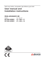
FIGURE 2 - TIMER
OPERATING
MODE SWITCH
DEMAND
INDICATOR
POSITION
OF DISPLAY
FEATURES
SEITING
BUITONS
time of day. (c) Press the DAY button to set the actual day of
the
week·;
The current time of day and day of the week are
now set in the timers memory.
Now the timer will operate to the inbuilt default programmes
which can be modified.
3) Set the 'switch on' and 'switch off' times for your central
heating periods and the group of days of the week in which
you wish them to operate as follows:
(a) Set the timer setting switch to ®. The display changes to
6:30 with the first switching mode ready to be set, .:~ (the
symbol will appear in the display to indicate that you are
setting a 'switch on' mode. A number 1 will also appear to
indicate that it is the first switching mode). (b) Keep pressing
the DAY button until the required day (or group of days) is
selected. (c) Press the HR and MIN buttons to set the actual
time for the beginning of the first heating period.
(d) Press the ® button again to set the second switching
mode (the.~ symbol will disappear from the display to indicate
that you are setting a 'switch off' mode. A number 2 will also
appear to indicate that it is the second switching mode). (e)
Keep pressing the DAY button until the required day (or group
of days) is selected. (f) Press the HR and MIN buttons to set
the actual time for the end of the first heating period. (g)
Q
Operations (d) to (f) can be repeated to give you up to eight
: heating periods in the selected group of days. You do not need
'" to use all of the switching modes.
Cl)
IMPORTANT: You must use the DAY button to select the
Q
required day (or groups of days) for each on/off period before
setting the time for each on/off period.
1
4) With the timer setting switch still at ®, continue pressing
I
the ® button to check your settings. Ensure that you have set
a switch off mode after each switch on mode and that the
times do not overlap. Set the timer setting switch to RUN and
the operating mode switch to AUTO. The timer will now
automatically control the boiler to provide central heating
during the operating periods you have just set. The .:~symbol
will appear in the display whenever the timer is operating
during an 'on' period.
GENERAL NOTES AND CARE OFYOUR
SYSTEM (FIGURE 1)
Mains ON/OFF switch. (Figure 1) This switch turns the boiler
on and off. The green light near the switch indicates it is in the
on position.
On/Off/Central heating temperature control. (Figure..1)
This control allows the temperature of the water leaving the
boiler for the heating system to be adjusted. Turning it
clockwise increases the temperature. Turning it fully anti-
clockwise turns the central heating off.
Domestic hot water temperature control. (Figure 1) This
control allows the temperature of the water leaving the boiler
57030

for the hot taps to be adjusted. Turning it clockwise increases
the temperaJure.
Pressure gauge This indicates the central heating system
pressure. The red pointer will have been set by your Installer
and must not be moved. The white pointer indicates the actual
pressure, which will increase as the system warms up. Do not
operate the boiler if the pressure falls below 0.5 bar. If this
happens, contact your Service Engineer to have the system
re-pressurised.
Overheat Lockout reset button If there is a burner control
malfunction, or an interruption in the power supply, the
overheat thermostat will switch the boiler off and the red
lockout neon will light. If the boiler continually goes to 'lockout'
a fault exists and you will need to call your Service Engineer.
Safety valve The boiler is fitted with a safety valve to release
excess pressure from the system if it overheats. If water or
steam is discharged from the end of the pipe, switch off the
boiler and contact your Service Engineer.
Flue terminal The flue terminal on the outside wall must not
be obstructed or damaged. In cold weather steam might
appear from the terminal this is quite normal for a high
efficiency boiler. In severe conditions check that the terminal
does not become blocked by snow.
Central heating system
The boiler is fitted with an automatic air vent which removes
air from the system as it leaves the boiler. Any air trapped in
the radiators needs removing by venting the radiators using
the vent screw at the top of the radiators. Only vent a radiator
if the top is cool and the bottom is hot. Excessive venting will
reduce the system pressure, so only vent when necessary and
check the system pressure as mentioned above.
Note: Your sealed system may incorporate a 'Top Up' vessel,
advice on how to use it should be obtained from your Installer.
Domestic hot water system.
The flow of water from the taps (hot or cold) depends upon the
mains water pressure, and in some homes it may not be
possible to use a number of taps at the same time.
The temperature of water leaving a hot tap depends on a lot of
variables, such as mains pressure, distance of the tap from
the boiler and the flow rate of the water leaving the tap. It may
take some time and experimenting with the temperature
control (see below) and how far you open a tap to achieve the
results you require. Remember, if you open a hot tap fully it
may not supply water at such a high temperature as when you
only open it half way.
The temperature of the hot water leaving the boiler for the hot
taps can be increased by turning the hot water temperature
control knob (see Fig. 1) clockwise.
ROUTINE SERVICING
To ensure the continued efficient and safe operation of the
GlIPpliance,it is recommended that servicing is canrJed·outat
regular intervalS, the frequency of which will vary, depending
on the installation conditions and usage. Service inspection
once a year is recommended.
Servicing must be completed by a competent (CORGI
registered) person.
CLEANING
To clean the appliance casing use a damp cloth and a little
detergent. Do not use an abrasive cleaner.
5"7030

SPARE PARTS AND SERVICE
All Centurion products are covered by a 12 month Warranty
and a nationwide network of Service Engineers.
In the unlikely event of a breakdown, please contact
Centurion on (01473) 747472, or alternatively your installation
or servicing company.
To help us provide you with a fast and efficient service,
please quote the boiler number and G.C. number. This can
be found on the label on the inside of the control panel door.
57030

57030
Indicates changes from
previous issue
CENTURION GAS PRODUCTS LTD
PO Box 323, Ipswich IP1 5JB Tel: 01473747472 Fax: 01473747479
Centurion Gas Products policy is one of continuous research and development.
This may necessitate alterations to this specification.
/