STEP 4: CHECK OUT YOUR DOOR OPERATING SYSTEM
CAUTION: THERE ARE NO USER SERVICEABLE PARTS
INSIDE TRANSMITTER OR RECEIVER
A. After installing your receiver and transmitter, check the operation of your radio controls by
moving approximately 35 feet back from the garage door, then press the transmitter button.
Operation at this distance should be reliable.
B. If the transmitter doesn’t activate the operator, check the coding switches on both the
transmitter and receiver to assure an “exact” match. (See Fig. 2 & 3). This may necessitate
a reprogramming of a Quik Code Classic transmitter to match the receiver coding switches.
C. If the distance is inadequate, check the battery and replace if necessary. (Also See Step 4D).
D. To maximize the operating distance move the transmitter to different locations in the car until
a satisfactory distance is achieved.
E. If the receiver is in the proximity of a metal beam or other obstruction it may be necessary to
relocate the receiver to increase the operating range.
F. If multiple receivers are mounted closer than 15 feet, blocking and interference may
occur. Relocate the receivers farther apart.
G. If system does not work at any distance, check that the receiver terminals are connected to the
proper operator terminals. See Step 2A.
P/N 190-107713 REV D
LINEAR LIMITED WARRANTY
This product is warranted to the consumer against defects in material and workmanship
for one year from the date of purchase. This warranty applies to first retail buyers of new
devices. Warrantor will repair, or at its option, replace, any device it finds that requires
service under this warranty, and will return the repaired or replaced device to the
consumer at the warrantor’s cost. For warrant service and shipping instructions contact
warrantor at the address shown below. Devices must be sent to warrantor for service at
owner’s expense. The remedies provided by this warranty are exclusive. Implied
warranties under state law are to the one year period of this written warranty. Some
states do not allow limitations on how long an implied warranty lasts, so the above
limitation may not apply to you. In order to be protected by this warranty, save your
proof of purchase and send copy with equipment should repair be required. This
warranty gives you specific legal rights, and you may also have other rights which vary
from state to state.
For warranty service and shipping instructions contact Linear at the phone number
shown below. In order to be protected by this warranty, save your proof of purchase and
send a copy with equipment should repair be required. All products returned for
warranty service require a Return Product Authorization Number (RPA#). Contact
Linear Technical Services at 1-800-421-1587 for an RPA# and other important details.
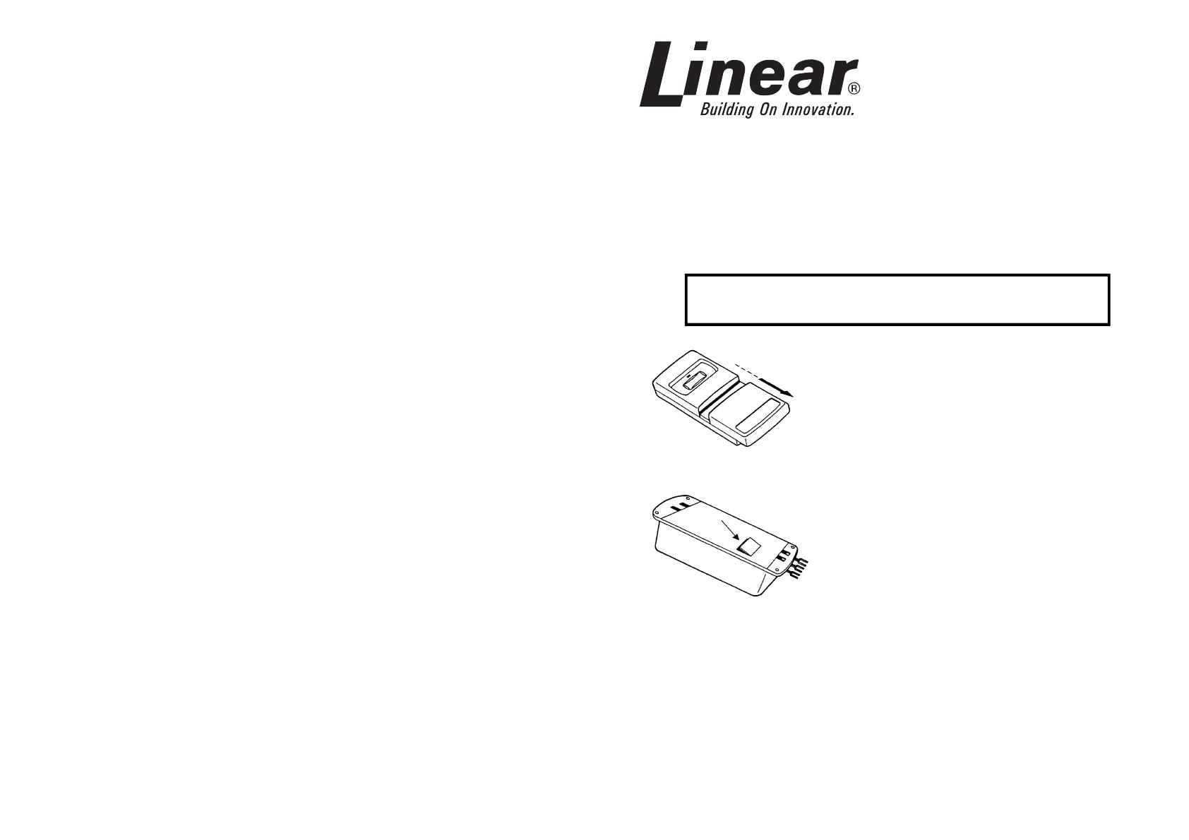
A. Remove the access cover from the front of the
transmitter by sliding the cover away from the top of
the transmitter. (See Fig. 1A).
B. Use a small screwdriver or knife to remove small
door on back of receiver to gain access to coding
switches. (See Fig. 1B)
IMPORTANT: THE EXACT SAME CODE MUST
BE SET ON BOTH THE TRANSMITTER AND
RECEIVER. IF JUST ONE SWITCH IS
MISMATCHED THE CONTROLS WILL NOT
FUNCTION.
Note: If installing Quik Code Classic transmitter(s) with a
99xx or 88xx receiver, first set your receiver coding
switches to your private code setting using the
instructions that follow THEN program your Quik Code
Classic transmitter (following the instructions included
with the transmitter) to match the receiver.
CAUTION: THE FACTORY PRESET CODE MUST
BE CHANGED TO SAFEGUARD AGAINST
UNAUTHORIZED OPERATION.
STEP 1: SET YOUR CODING SWITCHES
READ THE FOLLOWING INSTRUCTIONS
THOROUGHLY BEFORE STARTING INSTALLATION
Proper installation of your radio controls will assure years of trouble-free
operation.
Garage Door and Gate Operator Radio Controls
Models 9921, 9931, 8822, 8832, 8833
Installation Instructions
TRANSMITTER
Figure 1A
RECEIVER
Figure 1B
104384
104385
USA & Canada
(800) 421-1587 & (800) 392-0123
(760) 438-7000
Toll Free FAX (800) 468-1340
www.linearcorp.com


