Carf-Models BAE Hawk Mk 66 Assembly Manual
- Category
- Toys & accessories
- Type
- Assembly Manual

Skygate Collection
BAE Hawk Mk 66
Assembly Manual

Skygate Collection
BAE Hawk Mk 66
2
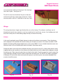
Thank you very much for purchasing our CARF Models Skygate Collection BAE Hawk, made
with the revolutionary Total Area Vacuum Sandwich (TAVS) technology.
Before you get started building and setting-up your aircraft, please make sure you have read
this instruction manual, and understood it. If you have any questions, please don’t hesitate to
contact your dealer, rep or CARF Models directly. Below are the contact details:
Email: feedback@carf-models.com
Telephone: Phone your CARF Dealer or rep - he will be there for you. A full list of dealers and
reps can be found on the CARF website:- http://www.carf-models.com
Liability Exclusion and Damages
You have acquired a kit, which can be assembled into a fully working R/C model when fitted
out with suitable accessories, as described in the instruction manual with the kit.
However, as manufacturers, we at CARF Models are not in a position to influence the way you
build and operate your model, and we have no control over the methods you use to install,
operate and maintain the radio control system components. For this reason we are obliged to
deny all liability for loss, damage or costs which are incurred due to the incompetent or
incorrect application and operation of our products, or which are connected with such operation
in any way. Unless otherwise prescribed by binding law, the obligation of the CARF Models
company to pay compensation is excluded, regardless of the legal argument employed. This
applies to personal injury, death, damage to buildings, loss of turnover and business, interruption
of business or other direct and indirect consequent damages. In all circumstances our total
liability is limited to the amount which you actually paid for this model.
BY OPERATING THIS MODEL YOU ASSUME FULL RESPONSIBILITY FOR YOUR ACTIONS.
It is important to understand that CARF Models is unable to monitor whether you follow the
instructions contained in this instruction manual regarding the construction, operation and
maintenance of the aircraft, nor whether you install and use the radio control system correctly.
For this reason we at CARF Models are unable to guarantee, or provide, a contractual agreement
with any individual or company that the model you have made will function correctly and safely.
You, as operator of the model, must rely upon your own expertise and judgement in acquiring
and operating this model.
Attention !
This ‘jet’ aircraft is a high-end product and can create an enormous risk for both pilot and
spectators,
if not handled with care & used according to the instructions. Make sure that you operate your
‘Hawk’ according to the laws and regulations governing model flying in the country of use. The
engine, landing gear, servos, linkages and control surfaces have to be attached properly.
Please use only the recommended servos and accessories. Make sure that the ‘Centre of

Skygate Collection
BAE Hawk Mk 66
3
Gravity’ is located in the recommended place. Use the nose heavy end of the CG range for your
first flights. A tail heavy plane can be an enormous danger for you and all spectators. Fix any
weights, and heavy items like batteries, very securely into the plane. Make sure that the plane
issecured properly when you start the engine. Have a helper hold your plane from the nose
before you start the engine. Make sure that all spectators are far behind, or far in front, of the
aircraft when running up the engine. Make sure that you range check your R/C system
thoroughly before the 1st flight. It is absolutely necessary to range check your complete R/C
installation first WITHOUT the engine running. Leave the transmitter antenna retracted or in the
case of 2.4ghz depress the range check button, and check the distance you can walk before ‘fail-
safe’ occurs. Then start the engine, run at about half throttle and repeat this range check. Make
sure that there is no range reduction before ‘fail-safe’ occurs. If the range with engine running is
less then with the engine off, please DON’T FLY at that time. Check that the wing and stab
retaining bolts are tight, and that all linkages are secured. Please don’t ignore our warnings, or
those provided by other manufacturers. They refer to things and processes which, if ignored,
could result in permanent damage or fatal injury.
Important/General Notes
Servo Choice
We strongly advise that you use the recommended servos and equipment listed in the manual.
Servo Screws
Fix the all the servos into the milled plywood servo mounts using the 2.9 Ø x13mm or 16mm
sheet metal screws provided in the kit, not the standard screws normally supplied with servos
by the servo manufacturer. This is because all the holes in our milled servo mounts are 2mm
diameter, due to our CNC manufacturing process, and this is too big for the normal screws
Building Sequence
The actual building sequence is your choice, but it is usually most efficient to start at the back of
the fuselage and work forwards.
Take Care
Composite sandwich parts are extremely strong, but fragile at the same time. Always keep in
mind that these contest airplanes are designed for minimum weight and maximum strength in
flight. Please take care of it, especially during transport, to make sure that none of the critical
parts and linkages are damaged. Always handle your airplane with great care, especially on the
ground and during transport, so you will have many hours of pleasure with it. To protect the
finished paint on the outside of the model from scratches and dents during building, cover your
work table with a piece of soft carpet, cloth or bubble- plastic. The best way to stop small spots
of glue getting stuck to the outside painted surfaces is to give the whole model 2 good coats of
clear car wax first, but of course you must be sure to remove this 100% properly before adding
any additional paint, markings or trim.
Adhesives and Solvents
Not all types of glues are suited to working with composite parts. Here is a selection of what

Skygate Collection
BAE Hawk Mk 66
4
we normally use, and what we can truly recommend. Please don’t use inferior quality glues -
you will end up with an inferior quality plane, that is not so strong or safe. Jet models require
good gluing techniques, due to the higher flying speeds, and hence higher loads on many of the
joints. We highly recommend that you use a slow filled thixotropic epoxy for gluing highly
stressed joints (eg: Hysol 9462). The self-mixing nozzles make it easy to apply exactly the
required amount, in exactly the right place, and it will not run or flow onto places where you don’t
want it! It takes about 1 - 2 hours to start to harden so it also gives plenty of time for accurate
assembly. Finally it gives a superb bond on all fibreglass and wood surfaces. Of course there are
many similar glues available, and you can use your favourite type.
1. CA glue ‘Thin’ and ‘Thick’ types. We recommend ZAP, as this is very high quality.
2. ZAP-O or Plasti-ZAP, odourless, or ZAP canopy glue 560 (for clear canopy)
3. 30 minute epoxy (stressed joints must be glued with at least 30 min & NOT 5 min epoxy).
4. Loctite Hysol 9462 or equivalent (optional, but highly recommended)
5. Epoxy laminating resin (12 - 24 hr cure) with hardener.
6. Milled glass fibre, for adding to slow epoxy for stronger joints.
7. Micro-balloons, for adding to slow epoxy for lightweight filling.
8. Thread-locking compound (Loctite 243, ZAP Z-42, or equivalent)
We take great care during production at the factory to ensure that all joints are properly glued,
but of course it is wise to check these yourself and re-glue any that might just have been
missed. When sanding areas on the inside of the composite sandwich parts to prepare the
surface for gluing something onto it, do NOT sand through the layer of lightweight glasscloth on
the inside foam sandwich. It is only necessary to rough up the surface, with 80/120 grit, and wipe
off any dust with acetone or de-natured alcohol (or similar) before gluing to make a perfect joint.
Of course, you should always prepare both parts to be joined before gluing for the highest
quality joints. Don’t use Acetone for cleaning external, painted, sur- faces as you will damage the
paint. Tip: For cleaning small (uncured) glue spots or marks off the painted surfaces you can use
old-fashioned liquid cigarette-lighter fuel, like ‘Ronsonol’ or equivalent. This does not damage the
paint, as Acetone and many other solvents will, and this is what we use at the factory. At CARF
Models we try our best to offer you a high quality kit, with outstanding value-for-money, and as
complete as possible. However, if you feel that some additional or different hardware should be
even good things can be made better !
Did you read the hints and warnings above and the instructions carefully? Did you understand
everything in this manual completely?
Then, and only then, let’s start assembling your Skygate Collection Hawk
If not, please read it again before you continue.

Skygate Collection
BAE Hawk Mk 66
5
Accessories
This list will help you chose the main additional items needed to finish your Skygate Collection
BAE Hawk.
Some of the recommendations are mandatory and some can be sourced and chosen by you.
The items we list here are highly recommended by CARF Models, and have been tested on
various prototype aircraft used during the development of this aeroplane.
1. Servos (minimum 8 high quality servos) All the main control surfaces require a minimum
20kg digital servo (two matched servos for the elevator control) such as the JR 8711 metal
geared servos. All the prototype Hawk models used JR 8711 servos.
2. Heavy duty aluminium servo arms are recommended for all flight surfaces
3. A receiver power supply system like the excellent Powerbox units are recommended using two
separate batteries through separate regulators. We used the PowerBox Cockpit SRS unit for the
example in this manual.
4. Turbines in the 160 - 200N thrust range have been used in the prototype aeroplanes. We used
a JetCat 180RX in the example for this manual.
5. Scale retractable Landing Gear sets are available from CARF Models (item no. 130500). The
Hawk was designed specifically around the German manufactured high quality sets that include
three units, plus specifically manufactured trailing link legs with associated ball raced wheels and
high quality brake units. A landing gear support pack is also available (item no. 130600). We
strongly recommend you use this proven high quality set comprising Jet Tronic valves, all gear
door rams, tubing, t-pieces and filler.
7. CARF models recommend a quality system radio system is used with 9 or preferebaly more
channels to allow individual servo connections to the receiver system. High quality extension
leads are required and a guide to the sizes and quantities required are listed below.
8. The Hawk features a large cockpit area which benefits from some additional detail. A very
detailed scale cockpit kit is available from CARF models to really complete your aircraft (item no.
130400)
9. CARF Models also have available an optional Speedbtake and associated pneumatic set.

Skygate Collection
BAE Hawk Mk 66
6
Hardware List
Nose Cylinders
M3 x 15 plus nylock x 2 pcs
M2 x 10 plus nut x 2 pcs
Plastic ball link to take M3 rod and M2 bolt x 2 pcs
Nose gear
M3 x 10 x 4pcs for n/g servo mounting
M3 dome head x 1pc
30mm M3 threaded rod x 1 pc
M3 ball link
M3 clevis
M3 x 10 bolt x 1pc
Large self tapping screws for N/G mounting x 4pcs
Intakes
2.9 x 13 sheet metal x 2pcs
Gear doors
M4 x 20 plus spike nuts x 2 pcs
M3 clevis x 2 pcs
M4 x 15 plus nylock x 4pcs
M2 ball links x 4pcs plus M2 threaded rod
Fuselage joining
M4 x 30 plus washer x 4pcs
M4 x 40 plus washer x 2pcs
Turbine / tailpipe mounting
M4 x 20 plus washer x 4pcs (8 pcs ideally if using 180 class turbines)
3mm pop rivets x 4pcs OR 2.9 x 10 self tapper x 4 pcs
2.9 x 10 sheet metal x 2 pcs for tailpipe rear mount
Elevator servos

Skygate Collection
BAE Hawk Mk 66
7
2.9 x 13 sheet metal x 8pcs
M3 ball links x 4pcs
M3 threaded rod 60mm x 2pcs
M3 x 12 x 2pcs
M3 x 15 plus nylock x 2pcs
Canopy
1 x canopy spring canopy release mechanism
Horizontal stab
M4 x 20mm plus 2 washers plus nylock x 1pc
M4 x 35 plus washers x 4pcs
M3 x 15 x 1 pc for stab cover
Vertical stab
M3 x 15 plus nylock for rudder horn x 1pc
Metal ball link to take M3 rod and M2 bolt x 1pc
M2 x 10 plus nut x 1pc
M3 threaded rod 105mm x 1pc
Wings
M3 x 135mm threaded rod x 2pcs
M3 x 90mm threaded rod x 2pcs
M3 metal ball link with M2 fixing x 4pcs
M3 metal clevis with 3mm pin and circlip x 2 pcs
M2 x 15 screw and nut x 2pcs
M3 nut x 4pcs
2.9 x 13 sheet metal x 16pcs
2.9 x 10 sheet metal x 8 pcs
M3 ball link x 2pcs
M3 x 15 with nylock x 2pcs
M6 x 40 x 2pcs
8 x large self tappers for gear mounting

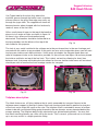
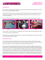
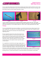
Thrust Tube Assembly and Turbine Installation
The thrust tube is manufactured as a stainless steel inner pipe rolled and spot welded for you at
the factory. At the tail end of the pipe there is an outer aluminium augmenter designed to help draw
cool air through the fuselage and over the pipe as well as
to give a scale appearance.
This tube is designed to work with the sizes of turbine
intended for the BAE Hawk. Turbines in the 180 to 200N
thrust class are perfect.
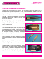
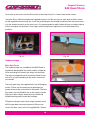
The first job is to fix the carbon bellmouth to the stainless
inner tube. The bellmouth is designed to go inside the
tail pipe and be fixed by M3 cap head screws or pop
rivets if available to you.
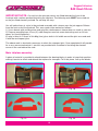
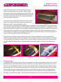
The Hawk was designed without full ducting and the
numerous examples in existence built as the original
Skygate models have used this system perfectly. It has
been found howver that it is a good idea to trim the bottom
of the bypass as shown as it benefits thrust output
particularly when using turbines at the lower end of the
scale.
Start by locating the 2 ply pieces which are CNC cut to fit
in the bypass as shown. These can be fixed in place with
epoxy.
In this example we fitted the thrust tube to the bypass
before trimming the bypass but trimming can be carried
out at any stage.
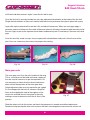
The pipe is made to fit securely over the bypass. The best
way to join the two pieces is to bring them together and
then rotate one or the other so the pipe slides over and on
to the bypass. Slide it up to the point it can go no further
where the diameter of the bypass diverges to form the
bellmouth. It must cover the bellmouth by at least 12mm.
Skygate Collection
BAE Hawk Mk 66
8
Fig. 1
Fig. 2
Fig. 3
Fig. 4

Skygate Collection
BAE Hawk Mk 66
9
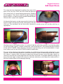
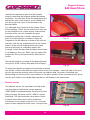
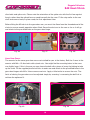
The setup has been designed to position the seam of the
pipe at the very top. Once you have fitted the pipe you
must check that it is square before permanently attaching
the two pieces. Then mark and drill the pipe through the
bypass Ø3mm, at 4 points equally spaced around the pipe.
Secure with 4 x pop rivets supplied.
At this point the bypass can be measured for trimming. See
figure 5 and 6 to show how to mark and measure the area
to be cut. Trim outside of the cut lines with a dremel or suitable rotary tool and tidy with files as
appropriate.
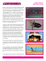
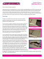
We then move on to fitting the turbine. It is easiest to do this whilst the assembly is outside the model
as the thrust pipe / bypass / turbine is effectively a self contained unit. This manual describes fitment
of the JetCat P180RX turbine however the bypass and mounitng rails will accommodate a larger
case turbine such as the JetCat P200SX without modification.
The rear of the tailcone of the turbine should be set at 45mm from the rear edge of the bypass (see
figure 6). Ensure this measurement is carried out carefully. Once you have this position set, ensure
the turbine is central within the pipe by observing through the rear end of the pipe. Adjust as
necessary and drill the 4 mounting holes Ø3.2mm then tap to M4. To provide additional strength to
the cut threads apply a drop of thin cyano to each hole and allow to set. Mount the turbine with 4 x
M4 allen head screws and re-check positioning.
Fig. 5
Fig. 6
Fig. 7
Fig. 8
Fig. 9

Skygate Collection
BAE Hawk Mk 66
10
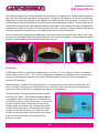
The turbine assembly can now be installed in the fuselage as a complete unit. Feed the pipe through the
rear half of the fuselage and position so the bypass is centred on the bearers and at the rear the outer
flange piece running at 45 degrees to the tailpipe is just within the rear of the fuselage - see figure 9. You
will notice there are 4 pre drilled holes in the ply pieces fitted to the bypass in figure 4. These holes can be
used to drill through to secure the turbine assembly to the bearers. We recommend using a 90 degree drill
attachment to achieve this easily. Drill Ø3.2mm then tap to M4 and apply a drop of cyano to the thread
leaving to set before inserting screws. Fix with M4 allen head screws and washers.
The rear of the thrust tube must be supported in some way to stop it from moving up / down or left / right.
Early kits are not shipped with a fixing method but one can make up a ply piece as shown above to secure
the tube. Some support may be needed at the bottom as well.
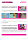
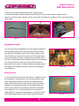
Fuel tank
CARF Models offer an optional moulded Kevlar fuel tank of 5.2 ltr capacity, which is installed in
the fuselage on the C of G . The tank is moulded with a deeper rear trough to retain fuel towards
the end of the tank and a blister in the front forward section for the vent to go up to allowing
maximum fill capacity.
Before starting assembly of the moulded tank it is important that any manufacturing debris left
over in the tank is washed out. Washing the tank with warm water and some washing detergent
works well. Ensure the tank is completely dry before you assemble it.
The tank comes fully joined and has been tested in
the factory for leaks. The recommended hardware
is provided in the kit. Take great care when you are
assembling all parts of the fuel system . To start with
de-burr inside the brass tubing with a new sharp
scalpel blade and remove any raised edges on the
outside caused by cutting. To aid sealing and help
prevent the fuel tube coming off, solder the short
lengths of tube provided a few mm back from each
end of the feed line and on the outside of the
breather line only.
Fig. 13
Fig. 10 Fig. 11 Fig. 12

Use Tygon tube for the clunk line, where the
clunkline passes through the baffle insert a section
of brass tube as the glass fibre edge can easily cut
through the tygon tube. The supplied soft clunk will
become heavier when charged with fuel and easily
reach all areas of the fuel tank.
Affix a small piece of tygon to the top pf the breather
pipe cut at an angle on sides as shown in figure 14
so there is less chance of the breather being
obstructed. The breather should be fashioned to so
the top protrudes into the blister at the top of the
tank made for this purpose.
The tank is very easily installed in the airframe on to the pre-formed tray in the rear fuselage and
secured with the velcro straps provided. At this point you may wish to consider where you will want
to place your turbine and radio anicllaries. Unlike many jet models the Skygate Hawk does not
need all equipment to be as far forward as possible. As you will see from figure 16 we have placed
the turbine ancillaries on top of the fuel tank. This is ideal, not only by allowing for short lines
between tank, fuel pump and turbine but also allows for the rear section to be more self contained
should you wish to remove the front fuselage section for transport.
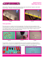
Tailplane description
The Hawk features an all flying tailplane that is easily removable for transport.Access to the
tailplane mount support is through a factory fitted rear fuselage hatch held in position by two pins
at the front and a single M3 screw at the rear. The tailplane itself is actuated by means of a 6mm
carbon tube with rose jointed fitting going forward to the two elevator servos mounted behind the
canopy opening. The tailplane bolts to two substantial rose jointed bearing blocks. You may feel
that these mounting blocks are a little stiff to the touch. This is normal , please do not try to loosen
up in any way as this is a highly precision fitting.
Skygate Collection
BAE Hawk Mk 66
11
Fig. 14
Fig. 15
Fig. 16

IMPORTANT NOTE: On early kits the elevator servos are fitted towards the front of the
fuselage with a carbon pushrod actuating the tailplane. The following work MUST be carried out
on the pre-fitted elevator pushrod. Do not skip this step.
You will notice there is a join in the pushrod assembly with a sleeve over the join approx 200mm
from the front end of the pushrod. This area needs to be worked as follows:-
1) Use a dremel with sanding drum and grind the reinforcement sleeve down as much as you can.
2) Prepare some 80g/sqm 10 cm (4") wide fiberglass and mix some laminating resin or 30 min
epoxy (or Hysol/Aeroproxy)
3) wrap at least 4-5 layers of this 80g (4oz) glass cloth in full width around the joint area and soak
it with the resin/epoxy glue.
The above work is absolutely necessary to attain the strongest joint. Once completed it will provide
for a very secure mechanism. Later kits are provided with a method of installing the elevator
servos in the rear behind the stab.
Main tailplane assembly
A piece of material is provided to attach between the bearing blocks in order to keep their position
making it easier to attach and detach the taiplane for transport. To fit this piece, line up the blocks
Skygate Collection
BAE Hawk Mk 66
12
Fig. 19
Fig. 20
Fig. 17
Fig. 18

and bolt the tailplane to them and then unbolt,
carefuly remoiving the tailplane without disturbing
the blocks. You can then attach the holding piece to
both blocks with a few drops of cyano. Make sure
you do not get any cyano in the threads of the
bearing blocks.
It is advisable at this point to fit the “bacon slicers”
to the tailplane. These are not functional in any way
on the model but are a scale feature and enhance
the looks of the aircraft. Assemble the parts
provided by gluing the 2 smaller side pieces for
each unit to the top half as shown in figure 20.
Temporarily fix the tailplane in place on the aircraft
and then tack the top and bottom half of the “bacon
slicers” to the central tailplane block with cyano
ensuring that there is no binding against the
fuselage. Install the top hatch and again check there
is no binding in this area. When you are happy with
the position fix in place permanently with hysol or
similar.
Secure the tailplane assembly to the bearing blocks
using the 4 of M4 x 35mm allen bolts with washers.
To attach the taiplane assembly to the elevator pushrod
use the M4 x 20mm allen bolt with nylock using a total of 4 washers - one each side of the rose
joint on the pushrod and one each at the outer nut and bolt end. For ease of mounting and
dismounting you can cyno the inner washers to the glass uprights. Make sure before each flying
session that all bolts are suitable tight and there is no binding in the mechanism.
Elevator servos
The elevator servos are mounted in the top of the
rear fuselage just behind the canopy opening.
CARF Models recommend each servo to be at least
25kg of torque. We have used 2 x JR8711 servos
fitted with 1.25 inch aluminium servo horns. Nylon
or plastic servo horns must not be used here.
Installation is very simple using 4 of 2.9 x 13 sheet
metal screws supplied for each servo. Using the two
Skygate Collection
BAE Hawk Mk 66
13
Fig. 21
Fig. 22
Fig. 23

Skygate Collection
BAE Hawk Mk 66
14
lengths of 60mm M3 rod supplied make up one
pushrod for each elevator with an M3 ball link
supplied on one end and screw into the M3 ball
links already attached to the elevator pushrod
assembly. The pushrod length should be 87mm
between centres. For extra strength you can sleeve
the pushrod with brass or carbon tube.
Make sure both servos are centred and moving in
the correct direction to work together moving the
tailplane up and down before attaching.
Ventral Fins
Install the ventral fins in the rear of the model before final fit of the turbine and thrust tube
assembly. The three tabs on each fin should be scuffed with a sheet of sandpaper before inserting
on the pre cut slots in the bottom of the fuselage note the larger end of the fin is towards the front
of the fuselage. From the inside of the fuselage apply enough thick cyano at each of the three
mounting tabs to ensure a secure bond to the pads.
Vertical Stabiliser / Fin & Rudder
Assembly
The fin assembly is supplied virtually completed for
you with the rudder pre-hinged and control horns in
place. All you have to do is fit the servo and pushrod
assembly.
CARF Models recommend a 25kg digital servo for
the rudder such as the JR8711. The servo mounting
Fig. 24
Fig. 25
Fig. 26
Fig. 27
Fig. 28

Skygate Collection
BAE Hawk Mk 66
15
plate is integral to the fin structure and the mounting
holes are pre drilled for you. Before installing the
servo make sure it is centred and fit a high strength
servo arm (aluminium or carbon reinforced is
recommended). A 10 - 11mm arm is the maximum
size that will fit in this area. This length of arm will
give plenty of rudder throw. Again before installing
the servo in the fin attach the metal ball link
supplied with M2 screw and nut, securing with
loctite. Now you are ready to install the servo in the
fin with 4 of 2.9 x 13mm sheet metal screws. You
will find you need to attach a short extension lead -
100mm or so to the rudder servo.
Taking the 105mm M3 threaded rod supplied for the
rudder pushrod, screw on one of the M3 ball links
supplied to one end. For the next step you might
find it easier to remove the rudder form the fin. This
is done by simply pulling out the piano wire hinge
from the bottom of the rudder. This will give you
access to screw the open end of the pushrod
through the rear of the fin and into the ball link
attached to the servo arm earlier. Take note from
the pictures that the rudder pushrod is operated on
a “diagonal” plane to give the best throws without
any binding.
Re-attach the rudder ensuring the piano wire has
not missed any of the hinge points and affix the
rudder ball link with M3 x 15 allen screw and nyloc
nut.
The fin assembly is secured to the fuselage using
the supplied aluminium spar which you will find is
pre drilled and fitted with an M3 captive nut for
securing inside the rear of the fuselage - see figure
31.
Using a dremel tool or similar cut an opening for the
Fig. 29
Fig. 30
Fig. 32
Fig. 31

servo extension lead to exit the top of the fuselage
near the fin post - see figure 32.
The fin fits over the aluminium fin post at the rear
and locates with the carbon peg at the front, finally
securing with an M3 x 15 allen bolt at the very front.
Wings
The wings have been largely pre-finished for you at the factory. The ailerons and flaps are all
hinged and control horns glued in so all you need to do is install your servos, the landing gear and
the small scale parts to the leading edge and top surface of the wing.
Aileron
In the small wood pack you will find ply pieces to make up the aileron servo mounts. Clean the pieces
with sandpaper and assemble with cyano making sure all joints are secure. For aileron actuation CARF
Models recommend 25kg torque digital servos such as the JR8711. Use a suitable aluminium servo arm.
We have used a JR unit installing the clevis to the hole 19mm from centre.
Screw the aileron servo with arm installed to the poly servo mount using 2.9 x 13mm sheet metal screws
supplied and cyano in position on the aileron servo hatch which you have rubbed with sandpaper around
the gluing area. Take care not to glue the servo itself to the hatch. Once the cyano has cured, remove the
servo and apply a bead of hysol or similar around the mounting area. You MUST also add a small piece
of fibreglass all around the mount and soak with epoxy to ensure the parts are securely bonded.Once
cured, re-install the servo.
Skygate Collection
BAE Hawk Mk 66
16
Fig. 33
Fig. 34
Fig. 35
Fig. 36

The aileron servo linkage is made up using the M3 x 90mm threaded rod with 3mm ball link at one end
and M3 aluminium clevis with 3mm pin at the servo end. Add a length of brass or carbon tube to the
outside of the pushrod for extra strength if deired. Attach the ball link end to the aileron horns with the M3
x 15 allen screw and nyloc nut supplied. Once you are happy with aileron throws and movement you can
affix the supplied plastic fairings to cover the mechansim. The servo hatch / mount is fixed to the wing
with 2.9 x 10mm sheet metal screws.
Flap
The flap surfaces are installed for you at the factory
with beautiful scale hinging. What remains is for you to
install the servo and linkage. CARF Models
recommend a 25kg torque digital servo like the JR
DS8711 for the flap surfaces.
We have used a JR aluminium arm at 38mm between
centres for the flap. Drill the servo arm at 38mm Ø3mm
and install the aluminium clevis supplied. Install the
Skygate Collection
BAE Hawk Mk 66
17
Fig. 37 Fig. 38
Fig. 39 Fig. 40
Fig. 41

Skygate Collection
BAE Hawk Mk 66
18
servo arm on the servo and install the servo in the wing using 2.9 x 13mm sheet metal screws.
Using the M3 x 135mm threaded rod supplied screw on 2 x M3 nuts (one at each end) and then screw
on the supplied aluminium ball link. Install the pushrod open end through the back of the wing and screw
in to the aluminium clevis on the servo arm. It is recommended to add a length of brass or carbon tube to
further strengthen the pushrod. Once happy with the flap throws tighten the nut at each end of the
pushrod.
Undercarriage
Main Gear Doors
The undercarriage set available for the BAE Hawk is
specifically designed for this model and fits straight on
to the mounting rails fitted in the wings and fuselage.
The legs are supplied in plain aluminium finish for you
to fit as is or paint according to the colour scheme of
your model.
The main gear legs are supplied with a set of fibreglass
covers. These are not necessary for operation but
greatly enhance the scale looks of the model. The front
gear doors are fully fitted for you at the factory and the
main gear doors simply attach to the pre fitted and
drilled mounting points inside the fuselage.
Fitting the main gear door rams simply requires you to
drill the gear door ram mounting posts Ø4mm and
attach the door rams with the supplied M4 x 20mm
Fig. 42 Fig. 43
Fig. 44
Fig. 45

allen bolts and spike nuts. Please note the orientation of the spike nuts with the flat face against
the ply rather than the spiked face as would normally be the case. Fit the stop collar to the ram
shaft and secure losely in place ready for final adjustment later.
Before fitting the M3 clevis to the gear door ram, you must trim 5mm from the threaded end of the
clevis to ensure smooth operation when fitted. Screw the clevis on to the ram as far as it will go
and attach to the pre drilled hole on the gear door hinge.
Nose Gear Doors
The mounts for the nose gear door rams are installed for you at the factory. Bolt the 2 rams to the
mounts with M3 x 15 allen bolts with nylock nuts. You might find the mounting holes in the rams
are slightly large. If this is the cse you can sleeve the bolt with a piece of scrap fuel tubing to take
up the slack. Fit the supplied plastic ball links to each ram and attach to the pre drilled holes in the
gear door hinges with M2 x 10mm screws and nuts. Apply a little loctite to secure the nuts. The
limits of closing the gear doors can be adjusted simply by screwing / unscrewing the ball link to
achieve the optimum fit.
Skygate Collection
BAE Hawk Mk 66
19
Fig. 46
Fig. 47 Fig. 48
Fig. 49 Fig. 50

Skygate Collection
BAE Hawk Mk 66
20
Nose Gear unit
The nose gear unit comes pre-assembled. In case you did not dis-assemble it for painting, ensure that all
parts are secure and tight before installation.
Attach the steering servo frame to the nose unit with the M3 dome head screw supplied and fit the servo
using the M3 x 10 allen bolts supplied. CARF Models recommend using an analog metal gear servo
such as the JR ES579.
Using the 30mm M3 threaded rod suppplied make up the sterring pushrod with M3 ball link and M3
clevis as shown. Install the linkage on a diagonal plane as shown in order to achieve good throws and no
issues with retracting / extending the gear.
Fit the 4mm air lines supplied to the nose gear unit and install in the fuselage as shown in figure 49 using
the large self tapping screws supplied.
Main Gear strut covers
You will find in your kit a pair of fibreglass strut covers for the main gear legs each in 2 halves. These
covers are handed so make sure the cover set you select is correct for the gear leg you are working on. If
you decide to paint your undercarriage please do this before fitting the strut covers.
Each strut cover half must be fitted and left to cure before the second half is added in order to achieve
the best result. You will need to trim the top off each strut cover so the area where the leg mounts into the
retract unit is kept clear. To start the joining process apply a liberal amount of silicone (we used bathroom
silicone sealant) only to the area where it will come into contact with the main leg to the inside of the half
you are working on. It is not necessary to put any form of glue or silicone around the knuckle joint for the
trailing leg or the supporting arm for this area. See figure 54. Fit the cover to the leg on a flat surface and
prop up where necessary with spacers to ensure the fit is central. Offer up the second half to see that it
Fig. 51
Fig. 52 Fig. 53
Page is loading ...
Page is loading ...
Page is loading ...
Page is loading ...
Page is loading ...
Page is loading ...
Page is loading ...
Page is loading ...
-
 1
1
-
 2
2
-
 3
3
-
 4
4
-
 5
5
-
 6
6
-
 7
7
-
 8
8
-
 9
9
-
 10
10
-
 11
11
-
 12
12
-
 13
13
-
 14
14
-
 15
15
-
 16
16
-
 17
17
-
 18
18
-
 19
19
-
 20
20
-
 21
21
-
 22
22
-
 23
23
-
 24
24
-
 25
25
-
 26
26
-
 27
27
-
 28
28


Carf-Models BAE Hawk Mk 66 Assembly Manual
- Category
- Toys & accessories
- Type
- Assembly Manual
Ask a question and I''ll find the answer in the document
Finding information in a document is now easier with AI
Related papers
-
Carf-Models ViperJet Mk II User manual
-
-
-
-
-
-
Carf-Models T-27 Tucano 1:4 Owner's manual
-
-
-