Lennox Signature XP19-024 Installation Instructions Manual
- Category
- Split-system air conditioners
- Type
- Installation Instructions Manual
This manual is also suitable for

06/09 505,331M
*2P0609* *P505331M*
Page 1
E2009 Lennox Industries Inc.
Dallas, Texas, USA
RETAIN THESE INSTRUCTIONS
FOR FUTURE REFERENCE
WARNING
Improper installation, adjustment, alteration,
service or maintenance can cause personal injury,
loss of life, or damage to property.
Installation and service must be performed by a
licensed professional installer (or equivalent) or a
service agency.
CAUTION
Physical contact with metal edges and corners
while applying excessive force or rapid motion can
result in personal injury. Be aware of, and use
caution when working near these areas during
installation or while servicing this equipment.
IMPORTANT
This unit must be matched with an indoor coil as
specified in Lennox’ Engineering Handbook.
Coils previously charged with HCFC−22 must be
flushed.
IMPORTANT
The Clean Air Act of 1990 bans the intentional
venting of refrigerant (CFCs, HCFCs AND HFCs) as
of July 1, 1992. Approved methods of recovery,
recycling or reclaiming must be followed. Fines
and/or incarceration may be levied for
noncompliance.
INSTALLATION
INSTRUCTIONS
Dave Lennox Signature
®
Collection XP19 Series
Units
HEAT PUMPS
505,331M
06/09
Supersedes 05/09
Table of Contents
Shipping and Packing List 1. . . . . . . . . . . . . . . . . . . . . .
Unit Dimensions 2. . . . . . . . . . . . . . . . . . . . . . . . . . . . . . .
XP19 Heat Pumps 2. . . . . . . . . . . . . . . . . . . . . . . . . . . . .
General Information 2. . . . . . . . . . . . . . . . . . . . . . . . . . .
Recovering Refrigerant from Existing System 4. . . . .
Removing Existing Outdoor Unit 5. . . . . . . . . . . . . . . . .
Positioning New Outdoor Unit 5. . . . . . . . . . . . . . . . . . .
Removing Panels 6. . . . . . . . . . . . . . . . . . . . . . . . . . . . .
New or Replacement Line Set 8. . . . . . . . . . . . . . . . . . .
Brazing Connections 9. . . . . . . . . . . . . . . . . . . . . . . . . . .
Removing Indoor Unit Metering Device 10. . . . . . . . . . .
Flushing the System 11. . . . . . . . . . . . . . . . . . . . . . . . . . .
Installing New Indoor Unit Metering Device 12. . . . . . . .
Testing for Leaks 12. . . . . . . . . . . . . . . . . . . . . . . . . . . . . .
Evacuating the System 14. . . . . . . . . . . . . . . . . . . . . . . . .
Servicing Unit Delivered Void of Charge 15. . . . . . . . . .
Electrical Connections 16. . . . . . . . . . . . . . . . . . . . . . . . .
Start−Up and Charging Procedures 16. . . . . . . . . . . . . . .
System Operations 21. . . . . . . . . . . . . . . . . . . . . . . . . . . .
Lennox System Operation Monitor (LSOM) 21. . . . . . .
Defrost System 24. . . . . . . . . . . . . . . . . . . . . . . . . . . . . . .
Maintenance 29. . . . . . . . . . . . . . . . . . . . . . . . . . . . . . . . . .
Two−Stage Compressor Check−out 30. . . . . . . . . . . . . . .
Homeowner Information 30. . . . . . . . . . . . . . . . . . . . . . . .
Field Operational Checklist 32. . . . . . . . . . . . . . . . . . . . .
Start−up and Performance Checklist 32. . . . . . . . . . . . . .
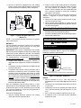
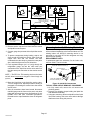
Shipping and Packing List1
Check the unit for shipping damage and listed times below
are intact. If damaged, or if parts are missing, immediately
contact the last shipping carrier.
1 Assembled outdoor unit.
1 Bag assembly which contains the followings:
1 Bushing (for low voltage wiring
2 Isolation grommets for liquid and suction lines
ISOLATION GROMMETS (2)
BUSHING (1)
Figure 1. Bag Assembly (Parts)
Litho U.S.A.

Page 2
505331M 06/09
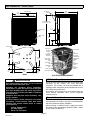
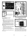
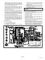
Unit Dimensions −− Inches (mm)2
39−1/2
(1003)
35−1/2
(902)
18−1/2
(470)
8 (203)
1 (25)
4−1/2
(114)
LIQUID LINE
INLET
ELECTRICAL
INLETS
SIDE VIEW
ACCESS VIEW
DISCHARGE AIR
4−5/8
(117)
BASE
16−7/8
(429)
8−3/4
(222)
26−7/8
(683)
3−3/4 (95)
30−3/4
(781)
3−1/8
(79)
SUCTION LINE
INLET
UNIT SUPPORT
FEET
37 (940) [−024, −036]
47 (1194) [−048, −060]
OUTDOOR FAN
RUN
CAPACITOR
TWO−STAGE
COMPRESSOR
COMPRESSOR
TERMINAL
PLUG
LOW
PRESSURE
SWITCH
HIGH
PRESSURE
SWITCH
CONTACTOR
DEFROST
CONTROL
SYSTEM
OPERATION
MONITOR
VAPOR VALVE
AND GAUGE
PORT
DISCHARGE
LINE
REVERSING
VALVE
VAPOR LINE
FILTER DRIER
XP19 PARTS ARRANGEMENT
WARNING
This product and/or the indoor unit it is matched
with may contain fiberglass wool.
Disturbing the insulation during installation,
maintenance, or repair will expose you to fiberglass
wool dust. Breathing this may cause lung cancer.
(Fiberglass wool is known to the State of California
to cause cancer.)
Fiberglass wool may also cause respiratory, skin,
and eye irritation.
To reduce exposure to this substance or for further
information, consult material safety data sheets
available from address shown below, or contact
your supervisor.
Lennox Industries Inc.
P.O. Box 799900
Dallas, TX 75379−9900
XP19 Heat Pumps3
The XP19 Heat Pumps, which will also be referred to in this
instruction as the outdoor unit, uses HFC−410A
refrigerant. This outdoor unit must be installed with a
matching indoor unit and line set as outlined in the Lennox
XP19 Engineering Handbook.
This outdoor unit is designed for use in systems that use
check thermal expansion valve (CTXV) refrigerant
metering devices.
General Information4
These instructions are intended as a general guide and do
not supersede local codes in any way. Consult authorities
who have jurisdiction before installation.
When servicing or repairing HVAC components, ensure
the fasteners are appropriately tightened. Table 1 shows
torque values for fasteners.

Page 3
XP19 SERIES
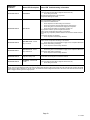
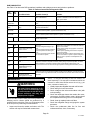
Table 1. Torque Requirements
Parts Recommended Torque
Service valve cap 8 ft.− lb. 11 NM
Sheet metal screws 16 in.− lb. 2 NM
Machine screws #10 28 in.− lb. 3 NM
Compressor bolts 90 in.− lb. 10 NM
Gauge port seal cap 8 ft.− lb. 11 NM
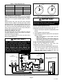
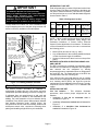
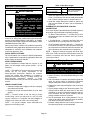
USING MANIFOLD GAUGE SETS
When checking the system charge, only use a manifold
gauge set that features low loss anti−blow back fittings.
See Figure 3 for a typical manifold gauge connection
setup.
Manifold gauge sets used with HFC−410A refrigerant
systems must be capable of handling the higher system
operating pressures. The gauges should be rated for use
with pressures of 0 − 800 on the high side and a low side of
30" vacuum to 250 psi with dampened speed to 500 psi.
Gauge hoses must be rated for use at up to 800 psi of
pressure with a 4000 psi burst rating.
OPERATING SERVICE VALVES
The liquid and vapor line service valves are used for
removing refrigerant, flushing, leak testing, evacuating,
checking charge and charging.
Each valve is equipped with a service port which has a
factory−installed valve stem.
IMPORTANT
Only use Allen wrenches of sufficient hardness
(50Rc − Rockwell Harness Scale minimum). Fully
insert the wrench into the valve stem recess.
Service valve stems are factory−torqued (from 9
ft−lbs for small valves, to 25 ft−lbs for large valves) to
prevent refrigerant loss during shipping and
handling. Using an Allen wrench rated at less than
50Rc risks rounding or breaking off the wrench, or
stripping the valve stem recess.
1
2
3
4
5
6
7
8
9
10
11
12
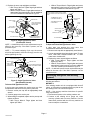
1/6 TURN
1
2
3
4
5
6
7
8
9
10
11
12
1/12 TURN
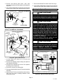
Figure 2. Cap Tightening Distances
IMPORTANT
To prevent stripping of the various caps used, the
appropriately sized wrench should be used and
fitted snugly over the cap before tightening.
To Access Angle−Type Service Port:
A service port cap protects the service port core from
contamination and serves as the primary leak seal.
1. Remove service port cap with an appropriately sized
wrench.
2. Connect gauge to the service port.
3. When testing is completed, replace service port cap and
tighten as follows:
D With Torque Wrench: Finger tighten and then
tighten per Table 1.
D Without Torque Wrench: Finger tighten and use an
appropriately sized wrench to turn an additional
1/6 turn clockwise as illustrated in Figure 2.
To Open and Close Angle−Type Service Valve:
A valve stem cap protects the valve stem from
contamination and assures a leak−free seal.
1. Remove stem cap with an appropriately sized wrench.
2. Use a service wrench with a hex−head extension
(3/16" for liquid-line valve sizes and 5/16" for
vapor-line valve sizes) to back the stem out
counterclockwise as far as it will go.
OUTDOOR
COIL
CHECK
EXPANSION VALVE
BI−FLOW
FILTER /
DRIER
TO
HFC−410
A DRUM
LOW
PRESSURE
COMPRESSOR
REVERSING VALVE
VAPOR
LINE
VALVE
MUFFLER
NOTE − Arrows indicate direction
of refrigerant flow.
CHECK EXPANSION VALVE
HEAT PUMP
LIQUID
SERVICE
PORT
GAUGE MANIFOLD
DISTRIBUTOR
INDOOR
COIL
VAPOR
SERVICE
PORT
HIGH
PRESSURE
LIQUID
LINE
VALVE
Figure 3. Typical Manifold Gauge Connection Setup

Page 4
505331M 06/09
3. Replace the stem cap and tighten as follows:
D With Torque Wrench: Tighten finger tight and then
tighten per Table 1.
D Without Torque Wrench: Finger tighten and use an
appropriately sized wrenched to turn an additional
1/12 turn clockwise as illustrated in Figure 2.
(VALVE STEM SHOWN
CLOSED) INSERT HEX
WRENCH HERE
VALVE STEM
FRONT-SEATED
TO OUTDOOR UNIT
SERVICE PORT
CORE
TO INDOOR
UNIT
SERVICE PORT
SERVICE PORT
CAP
CLOSED TO BOTH INDOOR
AND OUTDOOR UNITS
STEM CAP
Figure 4. Angle−Type Service Valve
(Font−Seated Closed)
NOTE A label with specific torque requirements may be
affixed to the stem cap. If the label is present, use the
specified torque.
NOTE To prevent stripping of the cap, the wrench
should be appropriately sized and fit snugly over the cap
before tightening the cap.
SERVICE PORT
SERVICE PORT
CORE
TO OUTDOOR UNIT
STEM CAP
(VALVE STEM SHOWN OPEN)
INSERT HEX WRENCH HERE
SERVICE PORT CAP
TO INDOOR
UNIT
OPEN TO BOTH
INDOOR AND
OUTDOOR UNITS
Figure 5. Angle−Type Service Valve
(Back−Seated Opened)
To Access Ball−Type Service Port:
A service port cap protects the service port core from
contamination and serves as the primary leak seal.
1. Remove service port cap with an appropriately sized
wrench.
2. Connect gauge to the service port.
3. When testing is completed, replace service port cap and
tighten as follows:
D With Torque Wrench: Finger tighten and then
tighten per Table 1.
D Without Torque Wrench: Finger tighten and use an
appropriately sized wrench to turn an additional
1/6 turn clockwise as illustrated in Figure 2.
BALL (SHOWN
CLOSED)
SERVICE PORT
CORE
TO INDOOR UNIT
TO OUTDOOR UNIT
TO OPEN ROTATE STEM
COUNTERCLOCKWISE 90°.
TO CLOSE ROTATE STEM
CLOCKWISE 90°.
SERVICE PORT
SERVICE PORT CAP
STEM CAP
VALVE
STEM
OPEN TO LINE SET WHEN VALVE IS CLOSED,
TO BOTH LINE SET AND UNIT WHEN VALVE IS
OPEN.
Figure 6. Ball−Type Service Valve
To Open and Close Ball−Type Service Valve:
A valve stem cap protects the valve stem from
contamination and assures a leak−free seal.
1. Remove stem cap with an appropriately sized wrench.
2. Use an appropriately sized wrenched to open. To open
valve, roate stem counterclockwise 90°. To close
rotate stem clockwise 90°.
3. Replace the stem cap and tighten as follows:
D With Torque Wrench: Finger tighten and then
tighten per Table 1.
D Without Torque Wrench: Finger tighten and use an
appropriately sized wrench to turn an additional
1/12 turn clockwise as illustrated in Figure 2.
NOTE A label with specific torque requirements may be
affixed to the stem cap. If the label is present, use the
specified torque.
Recovering Refrigerant from Existing
System5
Remove existing HCFC−22 refrigerant using one of the
following procedures:
METHOD 1:
If the existing outdoor unit is not equipped with shut−off
valves, or if the unit is not operational and you plan to use
the existing HCFC−22 to flush the system.
NOTE Use recovery machine instructions for specific
setup requirements.
1. Disconnect all power to the existing outdoor unit.
2. Connect to the existing unit a gauge set, clean
recovery cylinder and a recovery machine. Use the
instructions provided with the recovery machine on
how to setup the connections.

Page 5
XP19 SERIES
3. Remove all HCFC−22 refrigerant from the existing
system. Check gauges after shutdown to confirm that
the entire system is completely void of refrigerant.
MANIFOLD GAUGES
RECOVERY MACHINE
CLEAN RECOVERY
CYLINDER
OUTDOOR UNIT
Figure 7. Typical Refrigerant Recovery
(Method 1)
NOTE Use recovery machine instructions for specific
setup requirements.
METHOD 2:
Use this method if the existing outdoor unit is equipped
with manual shut−off valves, and plan on using new
HCFC−22 refrigerant to flush the system.
IMPORTANT: Some system configurations may contain
higher than normal refrigerant charge due to either large
internal coil volumes, and/or long line sets. The following
conditions may cause the compressor to stop functioning:
The following devices could prevent full system charge
recovery into the outdoor unit:
S Outdoor unit’s high or low−pressure switches (if
applicable) when tripped can cycled the compressor
OFF.
S Compressor can stop pumping due to tripped internal
pressure relief valve.
S Compressor has internal vacuum protection that is
designed to unload the scrolls (compressor stops
pumping) when the pressure ratio meets a certain
value or when the suction pressure is as high as 20
psig. (Compressor suction pressures should never be
allowed to go into a vacuum. Prolonged operation at
low suction pressures will result in overheating of the
scrolls and permanent damage to the scroll tips, drive
bearings and internal seals).
Once the compressor can not pump down to a lower
pressure due to one of the above system conditions, shut
off the suction valve. Turn OFF the main power to unit and
use a recovery machine to recover any refrigerant left in
the indoor coil and line set.
Perform the following task:
1. Start the existing HCFC−22 system in the cooling
mode and close the liquid line valve.
2. Pump as much of the existing HCFC−22 refrigerant
with the compressor back into the outdoor unit until
you have reached the limitations of the outdoor
system. Turn the outdoor unit main power OFF and
use a recovery machine to remove the remaining
refrigerant in the system.
NOTE It may be necessary to bypass the low pressure
switches if equipped to ensure complete refrigerant
evacuation.
3. When the low side system pressures reach 0 psig,
close the suction line valve.
4. Check gauges after shutdown to confirm that the
valves are not allowing refrigerant to flow back into the
low side of the system.
Removing Existing Outdoor Unit6
Perform the following task at the existing outdoor unit:
S Disconnect line set at the service valves.
S Disconnect electrical service at the disconnect switch.
S Remove old outdoor unit.
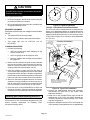
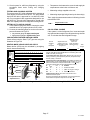
Positioning New Outdoor Unit7
CAUTION
In order to avoid injury, take proper precaution when
lifting heavy objects.
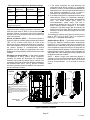
See Unit Dimensions on page 3 for sizing mounting slab,
platforms or supports. Refer to Figure 8 for mandatory
installation clearance requirements.
SEE NOTES BELOW THIS FIGURE FOR FURTHER DETAILS.
CONTROL PANEL
ACCESS LOCATION
Figure 8. Installation Clearances
NOTES:
S Service clearance of 30 in. (762 mm) must be
maintained on one of the sides adjacent to the control
box.
S Clearance to one of the other three sides must be 36
in. (914 mm)
.
S Clearance to one of the remaining two sides may be
12 in. (305 mm) and the final side may be 6 in. (152
mm)
.
S 48 in. (1219 mm) clearance required on top of unit.
S A clearance of 24 in. (610 mm) must be maintained
between two units.

Page 6
505331M 06/09
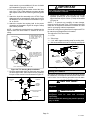
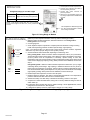
POSITIONING CONSIDERATIONS
INSTALL UNIT AWAY
FROM WINDOWS
TWO 90° ELBOWS INSTALLED
IN LINE SET WILL REDUCE
LINE SET VIBRATION.
Figure 9. Outside Unit Placement
Consider the following when positioning the unit:
S Some localities are adopting sound ordinances based
on the unit’s sound level registered from the adjacent
property, not from the installation property. Install the
unit as far as possible from the property line.
S When possible, do not install the unit directly outside
a window. Glass has a very high level of sound
transmission. For proper placement of unit in relation
to a window see the provided illustration in Figure 9.
PLACING UNIT ON SLAB
When installing unit at grade level, the top of the slab
should be high enough above grade so that water from
higher ground will not collect around the unit. The slab
should have a slope tolerance as described in Figure 10.
INSTALL UNIT LEVEL OR, IF ON A SLOPE, MAINTAIN SLOPE
TOLERANCE OF 2 DEGREES (OR 2 INCHES PER 5 FEET [50 MM
PER 1.5 M]) AWAY FROM BUILDING STRUCTURE.
MOUNTING
SLAB
BUILDING
STRUCTURE
GROUND
LEVEL
Figure 10. Slab Mounting at Ground Level
NOTE If necessary for stability, anchor unit to slab as
described in Stabilizing Unit on Uneven Surfaces on page
7.
ELEVATING THE UNIT
This unit is outfitted with elongated support feet as
illustrated in Figure 11 which uses a similar method for
elevating the unit.
LEG DETAIL
BASE
2" (50.8MM) SCH 40
FEMALE THREADED
ADAPTER
Figure 11. Elevated Slab Mounting using Feet
Extenders
If additional elevation is necessary, raise the unit by
extending the length of the unit support feet. This may be
achieved by using a 2" SCH 40 female threaded adapter.
The specified coupling will fit snuggly into the recessed
portion of the feet. Use additional 2" SCH 40 male threaded
adaptors which can be threaded into the female threaded
adaptors to make additional adjustments to the level of the
unit.
NOTE Keep the height of extenders short enough to
ensure a sturdy installation. If it is necessary to extend
further, consider a different type of field−fabricated
framework that is sturdy enough for greater heights.
Removing and Installing Panels8
CAUTION
To prevent personal injury, or damage to panels,
unit or structure, be sure to observe the following:
While installing or servicing this unit, carefully stow
all removed panels out of the way, so that the panels
will not cause injury to personnel, nor cause
damage to objects or structures nearby, nor will the
panels be subjected to damage (e.g., being bent or
scratched).
While handling or stowing the panels, consider any
weather conditions, especially windy conditions,
that may cause panels to be blown around and
battered.

Page 7
XP19 SERIES
WARNING
Unit must be grounded in accordance
with national and local codes.
Electric Shock Hazard. Can cause
injury or death.
Line voltage is present at all
components when unit is not in
operation on units with single-pole
contactors. Disconnect all remote
electric power supplies before
opening access panel. Unit may have
multiple power supplies.
ACCESS PANEL
Removal and reinstallation of the access panel is
illustrated in Figure 12.
REMOVE 4 SCREWS TO REMOVE PANEL FOR
ACCESSING COMPRESSOR AND CONTROLS.
INSTALL BY POSITIONING PANEL WITH HOLES
ALIGNED; INSTALL SCREWS AND TIGHTEN.
Figure 12. Access Panel
LOUVERED PANELS
Remove the louvered panels as follows:
1. Remove two screws, allowing the panel to swing open
slightly.
2. Hold the panel firmly throughout this procedure.
Rotate bottom corner of panel away from hinged
corner post until lower three tabs clear the slots as
illustrated in Figure 13, detail B.
3. Move panel down until lip of upper tab clears the top
slot in corner post as illustrated in Figure 13, detail A.
Position and Install PanelPosition the panel almost
parallel with the unit as illustrated in Figure 14, detail D with
the screw side as close to the unit as possible. Then, in a
continuous motion:
S Slightly rotate and guide the lip of top tab inward as
illustrated in Figure 13, details A and C; then upward
into the top slot of the hinge corner post.
S Rotate panel to vertical to fully engage all tabs.
S Holding the panel’s hinged side firmly in place, close
the right−hand side of the panel, aligning the screw
holes.
When panel is correctly positioned and aligned, insert the
screws and tighten.
Detail A
Detail C
Detail B
ROTATE IN THIS DIRECTION;
THEN DOWN TO REMOVE PANEL
SCREW
HOLES
LIP
IMPORTANT! DO NOT ALLOW
PANELS TO HANG ON UNIT BY TOP
TAB. TAB IS FOR ALIGNMENT AND
NOT DESIGNED TO SUPPORT
WEIGHT OF PANEL.
PANEL SHOWN SLIGHTLY
ROTATED TO ALLOW TOP TAB TO
EXIT (OR ENTER) TOP SLOT FOR
REMOVING (OR INSTALLING)
PANEL.
Figure 13. Removing/Installing Louvered Panels
(Detail A, B and C)
MAINTAIN MINIMUM PANEL ANGLE (AS CLOSE TO PARALLEL WITH THE UNIT
AS POSSIBLE) WHILE INSTALLING PANEL.
PREFERRED ANGLE
FOR INSTALLATION
Detail D
ANGLE MAY BE TOO
EXTREME
HOLD DOOR FIRMLY ALONG
THE HINGED SIDE TO MAINTAIN
FULLY−ENGAGED TABS
Figure 14. Removing/Installing Louvered Panels
(Detail D)
STABILIZING UNIT ON UNEVEN SURFACES
With unit positioned at installation site, remove two side
louvered panels to expose the unit base pan. Install the
brackets as illustrated in Figure 15 using conventional
practices; replace the panels after installation is complete.

Page 8
505331M 06/09
IMPORTANT
Unit Stabilizer Bracket Use (field−provided):
Always use stabilizers when unit is raised above the
factory height. (Elevated units could become
unstable in gusty wind conditions).
Stabilizers may be used on factory height units
when mounted on unstable an uneven surface.
To help stabilize an outdoor unit, some installations may
require strapping the unit to the pad using brackets and
anchors commonly available in the marketplace.
ONE BRACKET PER SIDE (MIN.); FOR EXTRA STABILITY,
2 BRACKETS PER SIDE, 2" FROM EACH CORNER.
CONCRETE SLAB − USE PLASTIC
PLASTIC ANCHOR (HOLE DRILL
1/4")PLASTIC SLAB − NO PLASTIC
ANCHOR (HOLE DRILL 1/8")
COIL
BASE PAN
CORNER POST
STABILIZING
BRACKET (18 GAUGE
METAL − 2" WIDTH;
HEIGHT AS REQ’D)
Slab Side Mounting
#10 1/2" LONG SELF−
DRILLING SHEET
METAL SCREWS
#10 1−1/4" LONG
HEX HD SCREW
AND FLATWASHER
MINIMUM 1
PER SIDE
Deck Top
Mounting
STABILIZING BRACKET
(18 GAUGE METAL − 2"
WIDTH; HEIGHT AS
REQ’D); BEND TO FORM
RIGHT ANGLE
FOR EXTRA
STABILITY
Figure 15. Installing Stabilizer Brackets
New or Replacement Line Set9
This section provides information on installation or
replacement of existing line set. If line set are not being
installed then proceed to Brazing Connections on page 12.
If refrigerant lines are routed through a wall, seal and
isolate the opening so vibration is not transmitted to the
building. Pay close attention to line set isolation during
installation of any HVAC system. When properly isolated
from building structures (walls, ceilings. floors), the
refrigerant lines will not create unnecessary vibration and
subsequent sounds. Also, consider the following when
placing and installing a high−efficiency air conditioner.
REFRIGERANT LINE SET
Field refrigerant piping consists of liquid and suction lines
from the outdoor unit (braze connections) to the indoor unit
coil (flare or sweat connections). Use Lennox L15 (sweat,
non−flare) series line set, or use field−fabricated refrigerant
lines as listed in Table 2.
Table 2. Refrigerant Line Set
Model
Field Connections Recommended Line Set
Liquid
Line
Suction
Line
Liquid
Line
Suction
Line
L15 Line Set
−024
−036
−048
3/8".
(10 mm)
7/8"
(22 mm)
3/8"
(10 mm)
7/8"
(22 mm)
L15−65
15 ft. − 50 ft.
(4.6 m − 15 m)
−060
3/8".
(10 mm)
1−1/8".
(29 mm)
3/8"
(10 mm)
1−1/8"
(29 mm)
Field
Fabricated
NOTE When installing refrigerant lines longer than 50
feet, see the Lennox Refrigerant Piping Design and
Fabrication Guidelines, or contact Lennox Technical
Support Product Applications for assistance. To obtain the
correct information from Lennox, be sure to communicate
the following points:
S Model (XP19) and size of unit (e.g. −060).
S Line set diameters for the unit being installed as listed
in Table 2 and total length of installation.
S Number of elbows and if there is a rise or drop of the
piping.
MATCHING WITH NEW OR EXISTING INDOOR COIL
AND LINE SET
The RFC1−metering line consisted of a small bore copper
line that ran from condenser to evaporator coil. Refrigerant
was metered into the evaporator by utilizing
temperature/pressure evaporation effects on refrigerant in
the small RFC line. The length and bore of the RFC line
corresponded to the size of cooling unit.
If the XP19 is being used with either a new or existing
indoor coil which is equipped with a liquid line which served
as a metering device (RFCI), the liquid line must be
replaced prior to the installation of the XP19 unit. Typically
a liquid line used to meter flow is 1/4" in diameter and
copper.
INSTALLING LINE SET
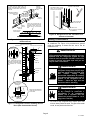
Line Set Isolation This reference illustrates
procedures, which ensure proper refrigerant line set
isolation:
S Installation of line set on horizontal runs is
illustrated in Figure 16.
S Installation of line set on vertical runs is illustrated in
Figure 17.
S Installation of a transition from horizontal to
vertical is illustrated in Figure 18.

Page 9
XP19 SERIES
METAL
SLEEVE
STRAPPING MATERIAL
(AROUND SUCTION
LINE ONLY)
TAPE OR
WIRE TIE
WIRE TIE
(AROUND
SUCTION LINE
ONLY)
FLOOR JOIST OR
ROOF RAFTER
TAPE OR
WIRE TIE
TO HANG LINE SET FROM JOIST OR
RAFTER, USE EITHER METAL STRAPPING
MATERIAL OR ANCHORED HEAVY NYLON
WIRE TIES.
8 FEET
8 FEET
STRAP THE SUCTION LINE TO
THE JOIST OR RAFTER AT 8 FEET
INTERVALS THEN STRAP THE
LIQUID LINE TO THE SUCTION
LINE.
FLOOR JOIST OR
ROOF RAFTER
Figure 16. Refrigerant Line Set: Installing
Horizontal Runs
NOTE − SIMILAR INSTALLATION
PRACTICES SHOULD BE USED
IF LINE SET IS TO BE INSTALLED
ON EXTERIOR OF OUTSIDE
WALL.
PVC
PIPE
FIBERGLASS
INSULATION
CAULK
OUTSIDE
WALL
SUCTION LINE
WRAPPED WITH
ARMAFLEX
LIQUID LINE
IMPORTANT! REFRIGERANT
LINES MUST NOT CONTACT
STRUCTURE.
OUTSIDE WALL
LIQUID LINE
SUCTION LINE
IMPORTANT - REFRIGERANT LINES
MUST NOT CONTACT WALL.
WOOD BLOCK
BETWEEN STUDS
STRAP
SLEEVE
WOOD BLOCK
STRAP
SLEEVE
WIRE TIE
WIRE TIE
WIRE TIE
INSIDE WALL
Figure 17. Refrigerant Line Set: Installing Vertical
Runs (New Construction Shown)
ANCHORED HEAVY NYLON
WIRE TIE OR AUTOMOTIVE
MUFFLER-TYPE HANGER
STRAP LIQUID LINE
TO SUCTION LINE
WALL
STUD
LIQUID LINE
METAL SLEEVE
SUCTION LINE − WRAPPED
IN ARMAFLEX
AUTOMOTIVE
MUFFLER-TYPE HANGER
Figure 18. Refrigerant Line Set: Transition from
Vertical to Horizontal
Brazing Connections10
Use the following procedure to braze the line set to the new
air conditioner unit. Figure 19 is provided as a general
guide for preparing to braze the line set to the air
conditioner unit.
WARNING
Polyol ester (POE) oils used with HFC−410A
refrigerant absorb moisture very quickly. It is very
important that the refrigerant system be kept
closed as much as possible. DO NOT remove line
set caps or service valve stub caps until you are
ready to make connections.
WARNING
Danger of fire. Bleeding the
refrigerant charge from only the high
side may result in the low side shell
and suction tubing being
pressurized. Application of a brazing
torch while pressurized may result in
ignition of the refrigerant and oil
mixture − check the high and low
pressures before unbrazing.
WARNING
When using a high pressure gas such
as dry nitrogen to pressurize a
refrigeration or air conditioning
system, use a regulator that can
control the pressure down to 1 or 2
psig (6.9 to 13.8 kPa).
1. Cut ends of the refrigerant lines square (free from
nicks or dents). Debur the ends. The pipe must remain
round, do not pinch end of the line.

Page 10
505331M 06/09
2
3
4
5
6
outdoor
UNIT
LIQUID LINE
SUCTION LINE
SERVICE
VALVE
SERVICE
VALVE
CUT AND DEBUR
ATTACH
GAUGES
WRAP
SERVICE
VALVE
FLOW NITROGEN
NITROGEN
BRAZE LINE SET
1
INSTALL CORE ONLY FOR
BOTH SERVICE PORTS after they
have coolED.
7
INDOOR UNIT
REMOVE CAP AND CORE FROM
BOTH LIQUID AND SUCTION
SERVICE PORTS
SERVICE PORT MUST BE
OPEN TO ALLOW EXIT
POINT FOR NITROGEN
Figure 19. Brazing Connections
2. Remove service cap and core from both the suction
and liquid line service ports.
3. Connect gauge low pressure side to liquid line service
valve.
4. To protect components during brazing, wrap a wet
cloth around the liquid line service valve body and
copper tube stub and use another wet cloth
underneath the valve body to protect the base paint.
Also, shield the light maroon R−410A sticker.
5. Flow regulated nitrogen (at 1 to 2 psig) through the
refrigeration gauge set into the valve stem port
connection on the liquid line service valve and out of
the valve stem port connection on the suction service
valve.
NOTE The RFCIV or TXV metering device at the indoor
unit will allow low pressure nitrogen to flow through the
system.)
6. Braze the liquid line to the liquid line service valve.
Turn off nitrogen flow. Repeat procedure starting at
paragraph 4 for brazing the suction line to the suction
service valve.
7. After all connections have been brazed, disconnect
manifold gauge set the from service ports, cool down
piping with wet rag and remove all wrappings. Do not
reinstall cores until after evacuation procedures.
Reinstall service caps if desired to close off refrigerant
ports.
Removing Indoor Unit Metering Device11
Remove the existing HCFC−22 refrigerant flow control
orifice or thermal expansion valve from the indoor coil. The
existing indoor unit HCFC−22 metering device is not
approved for use with HFC−410A refrigerant and may
prevent proper flushing.
REPLACEMENT PARTS
If replacement parts are necessary for the indoor unit,
order kit 69J46. The kit includes:
TEFLON RINGS (20)
BRASS NUTS (10)
LIQUID LINE ASSEMBLIES
(INCLUDES STRAINER) (10)
LIQUID LINE ORIFICE HOUSINGS (10)
LIQUID LINE
ASSEMBLY
COPPER
TUBE
PISTON
RETAINER
STRAINER
Figure 20. 69J46 Kit Components
TYPICAL FIXED ORIFICE REMOVAL PROCEDURE
1. On fully cased coils, remove the coil access and
plumbing panels.
2. Remove any shipping clamps holding the liquid line
and distributor assembly.
3. Using two wrenches, disconnect liquid line from liquid
line orifice housing. Take care not to twist or damage
distributor tubes during this process.

Page 11
XP19 SERIES
4. Remove and discard fixed orifice, valve stem
assembly if present and Teflon washer as illustrated in
Figure 21.
5. Use a field−provided fitting to temporary reconnect the
liquid line to the indoor unit’s liquid line orifice housing.
TEFLON RING
FIXED
ORIFICE
(Uncased Coil Shown)
BRASS NUT
LIQUID LINE ASSEMBLY
(INCLUDES STRAINER)
LIQUID LINE ORIFICE HOUSING
DISTRIBUTOR TUBES
DISTRIBUTOR
ASSEMBLY
REMOVE AND
DISCARD
WHITE TEFLON SEAL
(IF PRESENT)
Figure 21. Typical Fixed Orifice Removal
TYPICAL TXV REMOVAL PROCEDURE
TWO PIECE
PATCH PLATE
(UNCASED COIL
ONLY)
SUCTION
LINE
DISTRIBUTOR
ASSEMBLY
DISTRIBUTOR
TUBES
LIQUID
LINE
MALE EQUALIZER LINE
FITTING
SENSING
LINE
EQUALIZER
LINE
TXV
TEFLON
RING
(Uncased Coil Shown)
STUB END
TEFLON
RING
SENSING BULB
LIQUID LINE
ORIFICE HOUSING
LIQUID LINE ASSEMBLY
WITH BRASS NUT
Figure 22. Typical TXV Removal
1. On fully cased coils, remove the coil access and
plumbing panels.
2. Remove any shipping clamps holding the liquid line
and distributor assembly.
3. Disconnect the equalizer line from the TXV equalizer
line fitting on the suction line.
4. Remove the suction line sensing bulb.
5. Disconnect the liquid line from the TXV at the liquid line
assembly.
6. Disconnect the TXV from the liquid line orifice housing.
Take care not to twist or damage distributor tubes
during this process.
7. Remove and discard TXV and the two Teflon rings.
8. Use a field−provided fitting to temporary reconnect the
liquid line to the indoor unit’s liquid line orifice housing.
Flushing the System12
IMPORTANT
The line set and indoor unit coil must be flushed
with at least the same amount of clean refrigerant
that previously charged the system. Check the
charge in the flushing cylinder before proceeding.
IMPORTANT
If this unit is being matched with an approved line
set or indoor unit coil which was previously
charged with mineral oil, or if it is being matched
with a coil which was manufactured before
January of 1999, the coil and line set must be
flushed prior to installation. Take care to empty all
existing traps. Polyol ester (POE) oils are used in
Lennox units charged with HFC−410A refrigerant.
Residual mineral oil can act as an insulator,
preventing proper heat transfer. It can also clog
the expansion device, and reduce the system
performance and capacity.
Failure to properly flush the system per the
instructions below will void the warranty.
IMPORTANT
The Environmental Protection Agency (EPA)
prohibits the intentional venting of HFC refrigerants
during maintenance, service, repair and disposal of
appliance. Approved methods of recovery,
recycling or reclaiming must be followed.
LOW
PRESSURE
HIGH
PRESSURE
EXISTING
INDOOR
UNIT
GAUGE
MANIFOLD
INVERTED HCFC−22 CYLINDER
CONTAINS CLEAN HCFC−22 TO
BE USED FOR FLUSHING.
LIQUID LINE SERVICE VALVE
INLET
DISCHARGE
TANK
RETURN
CLOSED
OPENED
RECOVERY
CYLINDER
NOTE − THE INVERTED HCFC−22 CYLINDER MUST CONTAIN AT LEAST THE SAME
AMOUNT OF REFRIGERANT AS WAS RECOVERED FROM THE EXISTING SYSTEM.
RECOVERY MACHINE
NEW
OUTDOOR
UNIT
SUCTION LINE
SERVICE VALVE
SUCTION
LIQUID
Figure 23. Typical Flushing Connection

Page 12
505331M 06/09
CAUTION
This procedure should not be performed on
systems which contain contaminants (Example:
compressor burn out).
If the original system used:
S HCFC−22 refrigerant, then flush the system using the
procedure provided in this section.
S HFC−410A refrigerant, then proceed to Installing New
Refrigerant Metering Device.
REQUIRED EQUIPMENT
Equipment required to flush the existing line set and indoor
unit coil:
S Two clean HCFC−22 recovery bottles,
S Oilless recovery machine with pump-down feature,
S Two gauge sets (one for HCFC−22; one for
HFC−410A).
FLUSHING PROCEDURE
1. Connect the following:
S HCFC−22 cylinder with clean refrigerant to the
suction service valve,
S HCFC−22 gauge set to the liquid line valve,
S Recovery machine with an empty recovery tank to
the gauge set.
2. Set the recovery machine for liquid recovery and start
the recovery machine. Open the gauge set valves to
allow the recovery machine to pull a vacuum on the
existing system line set and indoor unit coil.
3. Invert the cylinder of clean HCFC−22 and open its
valve to allow liquid refrigerant to flow into the system
through the suction line valve. Allow the refrigerant to
pass from the cylinder and through the line set and the
indoor unit coil before it enters the recovery machine.
4. After all of the liquid refrigerant has been recovered,
switch the recovery machine to suction recovery so
that all of the HCFC−22 suction is recovered. Allow the
recovery machine to pull a vacuum on the system.
5. Close the valve on the inverted HCFC−22 drum and
the gauge set valves. Pump the remaining refrigerant
out of the recovery machine and turn the machine off.
Installing New Indoor Metering Device13
XP19 units use CTXV for metering refrigerant only. This
section provides instructions on installing CTXV
refrigerant metering device.
1
2
3
4
5
6
7
8
9
10
11
12
1/8 TURN
1
2
3
4
5
6
7
8
9
10
11
12
1/2 TURN
Figure 24. Tightening Distance
TYPICAL CTXV INSTALLATION PROCEDURE
The CTXV unit can be installed internal or external to the
indoor coil. In applications where an uncased coil is being
installed in a field−provided plenum, install the CTXV in a
manner that will provide access for field servicing of the
CTXV. Refer to Figure 25 for reference during installation
of CTXV unit.
TWO PIECE
PATCH PLATE
(UNCASED COIL
ONLY)
SUCTION
LINE
LIQUID LINE
ORIFICE
HOUSING
DISTRIBUTOR
TUBES
LIQUID
LINE
MALE EQUALIZER LINE
FITTING (SEE FIGURE 27
FOR FURTHER DETAILS)
SENSING
LINE
EQUALIZER
LINE
CTXV
TEFLON
RING
(Uncased Coil Shown)
SENSING BULB INSULATION IS
REQUIRED IF MOUNTED EXTERNAL
TO THE COIL CASING. SEE FIGURE 26
FOR BULB POSITIONING.
STUB END
TEFLON
RING
LIQUID LINE ASSEMBLY
WITH BRASS NUT
DISTRIBUTOR
ASSEMBLY
Figure 25. Typical TXV Installation
1. Remove the field−provided fitting that temporary
reconnected the liquid line to the indoor unit’s
distributor assembly.
2. Install one of the provided Teflon rings around the
stubbed end of the CTXV and lightly lubricate the
connector threads and expose surface of the Teflon
ring with refrigerant oil.
3. Attach the stubbed end of the CTXV to the liquid line
orifice housing. Finger tighten and use an appropriately

Page 13
XP19 SERIES
sized wrench to turn an additional 1/2 turn clockwise
as illustrated in Figure 24, or 20 ft−lb.
4. Place the remaining Teflon washer around the other
end of the CTXV. Lightly lubricate connector threads
and expose surface of the Teflon ring with refrigerant
oil.
5. Attach the liquid line assembly to the CTXV. Finger
tighten and use an appropriately sized wrench to turn
an additional 1/2 turn clockwise as illustrated in Figure
24, or 20 ft−lb.
6. Attach the suction line sensing bulb in the proper
orientation as illustrated in Figure 26 using the clamp
and screws provided.
NOTE Insulating the sensing bulb once installed may be
required when the bulb location is external to the coil
casing.
ON 7/8" AND LARGER LINES,
MOUNT SENSING BULB AT
EITHER THE 4 OR 8 O’CLOCK
POSITION. NEVER MOUNT
ON BOTTOM OF LINE.
12
ON LINES SMALLER THAN
7/8", MOUNT SENSING BULB
AT EITHER THE 3 OR 9
O’CLOCK POSITION.
12
BULB
SUCTION LINE
SUCTION LINE
NOTE − NEVER MOUNT ON BOTTOM OF LINE.
BULB
BULB
BULB
Figure 26. TXV Sensing Bulb Installation
7. Remove and discard either the flare seal cap or flare
nut with copper flare seal bonnet from the equalizer
line port on the suction line as illustrated in Figure 27.
SUCTION LINE
FLARE NUT
COPPER
FLARE SEAL
BONNET
MALE BRASS EQUALIZER
LINE FITTING
FLARE SEAL
CAP
OR
Figure 27. Copper Flare Seal Bonnet Removal
IMPORTANT
When removing the flare nut, ensure that the copper
flare seal bonnet is removed.
8. Connect the equalizer line from the TXV to the
equalizer suction port on the suction line. Finger
tighten the flare nut plus 1/8 turn (7 ft−lbs) as illustrated
in Figure 24.
NOTE To prevent any possibility of water damage,
properly insulate all parts of the TXV assembly that may
sweat due to temperature differences between the valve
and its surrounding ambient temperatures.
See the XP19 Engineering Handbook for approved CTXV
kit match−ups and application information.
The reference CTXV kits include:
1 CTXV
2 Teflon rings
1 1 1/4" wide copper mounting strap for sensing bulb
2 #10 hex head bolts and nuts for securing sensing bulb
CTXV (1)
COPPER
MOUNTING
STRAP (1)
HEX HEAD BOLTS
AND NUTS (2)
TEFLON
RINGS (2)
Figure 28. CTXV Kit Components
Testing for Leaks14
After the line set has been connected to the indoor unit and
air conditioner, check the line set connections and indoor
unit for leaks. Use the following procedure to test for leaks:
IMPORTANT
Leak detector must be capable of sensing HFC
refrigerant.
WARNING
Refrigerant can be harmful if it is inhaled.
Refrigerant must be used and recovered
responsibly.
Failure to follow this warning may result in personal
injury or death.

Page 14
505331M 06/09
WARNING
When using a high pressure gas such
as dry nitrogen to pressurize a
refrigeration or air conditioning
system, use a regulator that can
control the pressure down to 1 or 2
psig (6.9 to 13.8 kPa).
WARNING
Fire, Explosion and Personal Safety
Hazard.
Failure to follow this warning could
result in damage, personal injury or
death.
Never use oxygen to pressurize or
purge refrigeration lines. Oxygen,
when exposed to a spark or open
flame, can cause damage by fire and/
or an explosion, that could result in
personal injury or death.
1. Connect an HFC−410A manifold gauge set high
pressure hose to the suction valve service port.
(Normally, the high pressure hose is connected to the
liquid line port; however, connecting it to the suction
port better protects the manifold gauge set from high
pressure damage.)
2. With both manifold valves closed, connect the cylinder
of HFC−410A refrigerant to the center port of the
manifold gauge set. Open the valve on the HFC−410A
cylinder (suction only).
3. Open the high pressure side of the manifold to allow
HFC−410A into the line set and indoor unit. Weigh in
a trace amount of HFC−410A. [A trace amount is a
maximum of two ounces (57 g) refrigerant or three
pounds (31 kPa) pressure]. Close the valve on the
HFC−410A cylinder and the valve on the high pressure
side of the manifold gauge set. Disconnect the
HFC−410A cylinder.
4. Connect a cylinder of dry nitrogen with a pressure
regulating valve to the center port of the manifold
gauge set.
5. Adjust dry nitrogen pressure to 150 psig (1034 kPa).
Open the valve on the high side of the manifold gauge
set in order to pressurize the line set and the indoor unit.
6. After a few minutes, open one of the service valve
ports and verify that the refrigerant added to the
system earlier is measurable with a leak detector.
7. After leak testing disconnect gauges from service
ports.
Evacuating the System15
Evacuating the system of non−condensables is critical for
proper operation of the unit. Non−condensables are
defined as any gas that will not condense under
temperatures and pressures present during operation of
an air conditioning system. Non−condensables and water
suction combine with refrigerant to produce substances
that corrode copper piping and compressor parts.
WARNING
Danger of Equipment Damage. Avoid deep
vacuum operation. Do not use compressors to
evacuate a system. Extremely low vacuums can
cause internal arcing and compressor failure.
Damage caused by deep vacuum operation will
void warranty.
IMPORTANT
Use a thermocouple or thermistor electronic
vacuum gauge that is calibrated in microns. Use an
instrument capable of accurately measuring down
to 50 microns.
NOTE Remove cores from service valves if not already
done.
1. Connect manifold gauge set to the service valve ports
as follows:
S low pressure gauge to suction line service valve
S high pressure gauge to liquid line service valve
2. Connect micron gauge.
3. Connect the vacuum pump (with vacuum gauge) to
the center port of the manifold gauge set.
4. Open both manifold valves and start the vacuum
pump.
5. Evacuate the line set and indoor unit to an absolute
pressure of 23,000 microns (29.01 inches of
mercury).
NOTE During the early stages of evacuation, it is
desirable to close the manifold gauge valve at least once to
determine if there is a rapid rise in sure indicates a
relatively large leak. If this occurs, repeat the leak testing
procedure.
NOTE The term absolute pressure means the total
actual pressure within a given volume or system, above
the absolute zero of pressure. Absolute pressure in a
vacuum is equal to atmospheric pressure minus vacuum
pressure.
6. When the absolute pressure reaches 23,000 microns
(29.01 inches of mercury), close the manifold gauge
valves, turn off the vacuum pump and disconnect the
manifold gauge center port hose from vacuum pump.
Attach the manifold center port hose to a dry nitrogen

Page 15
XP19 SERIES
cylinder with pressure regulator set to 150 psig (1034
kPa) and purge the hose. Open the manifold gauge
valves to break the vacuum in the line set and indoor
unit. Close the manifold gauge valves.
7. Shut off the dry nitrogen cylinder and remove the
manifold gauge hose from the cylinder. Open the
manifold gauge valves to release the dry nitrogen from
the line set and indoor unit.
8. Reconnect the manifold gauge to the vacuum pump,
turn the pump on, and continue to evacuate the line set
and indoor unit until the absolute pressure does not
rise above 500 microns (29.9 inches of mercury) within
a 20−minute period after shutting off the vacuum pump
and closing the manifold gauge valves.
9. When the absolute pressure requirement above has
been met, disconnect the manifold hose from the
vacuum pump and connect it to an upright cylinder of
HFC−410A refrigerant. Open the manifold gauge valve
1 to 2 psig in order to release the vacuum in the line set
and indoor unit.
10. Perform the following:
A Close manifold gauge valves.
B Shut off HFC−410A cylinder.
C Reinstall service valve cores by removing
manifold hose form service valve. Quickly install
core with core tool while maintaining a positive
system pressure.
D Replace the stem caps and secure finger tight,
then tighten an additional one−sixth (1/6) of a turn
as illustrated in Figure 2.
Servicing Units Delivered Void of
Charge16
If the outdoor unit is void of refrigerant, clean the system
using the procedure described below.
1. Use nitrogen to pressurize the system and check for
leaks. Repair all leaks.
2. Evacuate the system to remove as much of the
moisture as possible.
3. Use nitrogen to break the vacuum and install a new
filter drier in the system.
4. Evacuate the system again. Then, weigh the
appropriate amount of HFC−410A refrigerant as listed
on unit nameplate into the system.
5. Monitor the system to determine the amount of
moisture remaining in the oil. It may be necessary to
replace the filter drier several times to achieve the
required dryness level. If system dryness is not
verified, the compressor will fail in the future.
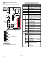
SHIPPED AS SHOWN ABOVE WITH TERMINAL CRIMPED TO BLUE
WIRE; USE TERMINAL OR CUT OFF TERMINAL AND SPLICE BLUE
WIRE WITH Y2 WIRE TO INDOOR UNIT.
BLUE WIRE
WITH CRIMPED
TERMINAL
DEFROST
BOARD
DETAIL
Y2 OUT
Figure 29. XP19 Wiring

Page 16
505331M 06/09
Electrical Connections17
WARNING
Electric shock hazard. Can cause
injury or death.
Line voltage is present at all
components on units with single−pole
contactors, even when unit is not in
operation!
Unit may have multiple power
supplies. Disconnect all remote
electric power supplies before
opening access panel.
Unit must be grounded in accordance
with national and local codes.
In the U.S.A., wiring must conform with current local codes
and the current National Electric Code (NEC). In Canada,
wiring must conform with current local codes and the current
Canadian Electrical Code (CEC).
Refer to the furnace or blower coil installation instructions
for additional wiring application diagrams and refer to unit
nameplate for minimum circuit ampacity and maximum
overcurrent protection size.
230VAC SUPPLY VOLTAGE
The XP19 outdoor unit is rated for 230VAC applications
only. A hard-start kit is required for applications where the
supply voltage is less than 230VAC.
24VAC TRANSFORMER
Use the transformer provided with the furnace or coil
blower for low-voltage control power (24VAC − 40 VA
minimum)
NOTE The addition of accessories to the system could
exceed the 40 VA power requirement of the
factory-provided transformer. Measure the system’s
current and voltage after installation is complete to
determine transformer loading. If loading exceeds the
factory-provided transformer capacity, a larger
field-provided transformer will need to be installed in the
system.
WIRING CONNECTIONS
1. Install line voltage power supply to unit from a properly
sized disconnect switch.
2. Ground unit at unit disconnect switch or to an earth
ground.
NOTE Connect conduit to the unit using a proper
conduit fitting. Units are approved for use only with
copper conductors. A complete unit wiring diagram is
located on the back side of the unit’s access panel.
NOTE For proper voltages, select thermostat wire
gauge per the following chart:
Table 3. Wire Run Length
Wire Run Length AWG # Insulation Type
less than 100’ (30m) 18
color−coded, temperature
rating 35
º
C minimum
more than 100’ (30m) 16
3. Install room thermostat (ordered separately) on an
inside wall approximately in the center of the area and
5 feet (1.5 m) from the floor. Do not install on an outside
wall or where sunlight, drafts or vibrations affect it.
4. Install low voltage wiring from outdoor to indoor unit
and from thermostat to indoor unit as illustrated in
Figure 29.
THERMOSTAT SECOND−STAGE COOLING
CONNECTIONS
The Lennox System Operation Monitor (LSOM) requires a
twos−stage room thermostat to operating properly.
S Y2 Room Thermostat Wire Connect the Y2 room
thermostat wire from the outdoor unit to the Y2 input
on the DCB.
S L Terminal Wiring Connect L terminal of the room
thermostat to the L (brown) field wire connection.
S Y2 DC Solenoid Connector (DC SOL) The two−pin
DC solenoid connector is connected at the factory to
the compressor second−state solenoid connector. No
field connections are required for this component.
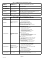
NOTE Wiring the module incorrectly will cause false
LED codes. Table 14 describes LED operation when the
module is incorrectly wired and the action required to
correct the problem.
Start−Up and Charging Procedures18
IMPORTANT
If unit is equipped with a crankcase heater, it should
be energized 24 hours before unit start−up to
prevent compressor damage as a result of slugging.
1. Rotate fan to check for binding.
2. Inspect all factory− and field−installed wiring for loose
connections.
3. After evacuation is complete, open both the liquid and
vapor line service valves to release the refrigerant
charge contained in outdoor unit into the system.
4. Replace the stem caps and tighten to the value listed
in Table 1.
5. Check voltage supply at the disconnect switch. The
voltage must be within the range listed on the unit’s
nameplate. If not, do not start the equipment until you
have consulted with the power company and the
voltage condition has been corrected.
6. Set the thermostat for a cooling demand. Turn on
power to the indoor indoor unit and close the outdoor
unit disconnect switch to start the unit.
7. Recheck voltage while the unit is running. Power must
be within range shown on the nameplate.

Page 17
XP19 SERIES
8. Check system for sufficient refrigerate by using the
procedures listed under Testing and Charging
System.
TESTING AND CHARGING SYSTEM
This system uses HFC−410A refrigerant which operates at
much higher pressures than HCFC−22. The pre−installed
liquid line filter drier is approved for use with HFC−410A
only. Do not replace it with components designed for use
with HCFC−22. This unit is NOT approved for use with coils
which use capillary tubes as a refrigerant metering device.
SETTING UP TO CHECK CHARGE
1. Close manifold gauge set valves. Connect the center
manifold hose to an upright cylinder of HFC−410A.
2. Connect the manifold gauge set to the unit’s service
ports as illustrated in Figure 3.
D low pressure gauge to vapor service port
D high pressure gauge to liquid service port
COOLING MODE INDOOR AIRFLOW CHECK
Check airflow using the Delta−T (
DT) process using the
illustration in Figure 30.
HEATING MODE INDOOR AIRFLOW CHECK
Blower airflow (CFM) may be calculated by energizing
electric heat and measuring:
S Temperature rise between the return air and supply air
temperatures at the indoor coil blower unit,
S Measuring voltage supplied to the unit,
S Measuring amperage being drawn by the heat unit(s).
Then, apply the measurements taken in following formula
to determine CFM:
CFM =
Amps x Volts x 3.41
1.08 x Temperature rise (F)
CALCULATING CHARGE
If the system is void of refrigerant, first, locate and repair
any leaks and then weigh in the refrigerant charge into the
unit. To calculate the total refrigerant charge:
Amount
specified
on
nameplate
Adjust amount. for
variation in line set
length listed on Table
in Figure 31.
Additional charge
specified per
indoor unit
match−up listed in
Tables 4 through
7.
Total
charge
+ + =
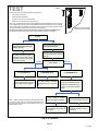
1. Determine the desired DTMeasure entering air temperature
using dry bulb (A) and wet bulb (B). DT is the intersecting value of A
and B in the Table (see triangle).
2. Find temperature drop across coilMeasure the coil’s dry bulb
entering and leaving air temperatures (A and C). Temperature Drop
Formula: (T
Drop
) = A minus C.
3. Determine if fan needs adjustmentIf the difference between the
measured T
Drop
and the desired DT (T
Drop
–DT) is within +3º, no ad-
justment is needed. See examples: Assume DT = 15 and A temp. =
72º, these C temperatures would necessitate stated actions:
Cº T
Drop
– DT = ºF ACTION
53º 19 – 15 = 4 Increase the airflow
58º 14 – 15 = −1 (within +3º range) no change
62º 10 – 15 = −5 Decrease the airflow
4. Adjust the fan speedSee indoor unit instructions to in-
crease/decrease fan speed.
Changing air flow affects all temperatures; recheck temperatures to
confirm that the temperature drop and DT are within +3º.
DT
80 24 24 24 23 23 22 22 22 20 19 18 17 16 15
78 23 23 23 22 22 21 21 20 19 18 17 16 15 14
76 22 22 22 21 21 20 19 19 18 17 16 15 14 13
74 21 21 21 20 19 19 18 17 16 16 15 14 13 12
72 20 20 19 18 17 17 16 15 15 14 13 12 11 10
70 19 19 18 18 17 17 16 15 15 14 13 12 11 10
57 58 59 60 61 62 63 64 65 66 67 68 69 70
Temp.
of air
entering
indoor
coil ºF
INDOOR
COIL
DRY
BULB
DRY
BULB
WET
BULB
B
T
Drop
19º
A
Dry−bulb
Wet−bulb ºF
A
72º
B
64º
C
53º
air flowair flow
All temperatures are
expressed in ºF
Figure 30. Checking Indoor Airflow over Evaporator Coil using Delta−T Chart

Page 18
505331M 06/09
WEIGH IN
1. Check Liquid and suction line pressures
2. Compare unit pressures with Table 8,
Normal Operating Pressures.
3. Conduct leak check; evacuate as
previously outlined.
4. Weigh in the unit nameplate charge plus
any charge required for line set differences
over feet.
Liquid Line
Set Diameter
Ounces per 5 feet (g per 1.5 m)
adjust from 15 feet (4.6 m) line set*
3/8" (9.5 mm)
3 ounce per 5’ (85 g per 1.5 m)
NOTE − *If line length is greater than 15 ft. (4.6 m), add this
amount. If line length is less than 15 ft. (4.6 m), subtract this
amount.
Refrigerant Charge per Line Set Length
This nameplate is for illustration purposes
only. Go to actual nameplate on outdoor
unit for charge information.
Figure 31. Using Weigh In Method
1 Check the airflow as illustrated in Figure 30 to be sure the indoor airflow is as required.
(Make any air flow adjustments before continuing with the following procedure.)
2 Measure outdoor ambient temperature; determine whether to use cooling mode or
heating mode to check charge.
3 Connect gauge set.
4 Check liquid and vapor line pressures. Compare pressures with either cooling or heating
mode normal operating pressures in Table 8 (second stage − high capacity).
NOTE − The reference table is a general guide. Expect minor pressure variations. Significant
differences may mean improper charge or other system problem.)
5 Set thermostat for heat/cool demand, depending on mode being used:
Using cooling modeWhen the outdoor ambient temperature is 60°F (15°C) and above.
Target subcooling values (second stage − high capacity) in Table 8 are based on 70 to 80°F
(21−27°C) indoor return air temperature; if necessary, operate heating to reach that
temperature range; then set thermostat to cooling mode setpoint to 68ºF (20ºC) which should
call for second stage (high capacity) cooling. When pressures have stabilized, continue with
step 6.
Using heating modeWhen the outdoor ambient temperature is below 60°F (15°C). Target
subcooling values (second stage − high capacity) in Table 8 are based on 65−75°F (18−24°C)
indoor return air temperature; if necessary, operate cooling to reach that temperature range;
then set thermostat to heating mode setpoint to 77ºF (25ºC) which should call for second stage
(high capacity) heating. When pressures have stabilized, continue with step 6.
6 Read the liquid line temperature; record in the LIQº space.
7 Read the liquid line pressure; then find its corresponding temperature in the temperature/
pressure chart listed in Table 9 and record it in the SATº space.
8 Subtract LIQº temp. from SATº temp. to determine subcooling; record it in SCº space.
9 Compare SCº results with tables below, being sure to note any additional charge for line set
and/or match−up.
10 If subcooling value is greater than shown in Tables 4 through 7 for the applicable unit, remove
refrigerant; if less than shown, add refrigerant.
11 If refrigerant is added or removed, repeat steps 4 through 10 to verify charge.
USE COOLING
MODE
USE HEATING
MODE
60ºF (15º)
SATº
LIQº –
SCº =
SUBCOOLING
Figure 32. Using Subcooling Method Second Stage (High Capacity)

Page 19
XP19 SERIES
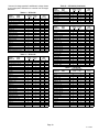
** Amount of charge required in additional to charge shown
on unit nameplate. Remember to consider line set length
difference.
Table 4 XP19−024
INDOOR HEAT
MATCH−UP PUMP
TargetSubcooling
HeatingCooling
(+
5ºF)(+1ºF)
**Add
charge
lb oz
C33−31 12 7 0 1
C33–38 SN# before SN#6007K 31 7 0 6
C33–38 SN#6007K and after 10 8 0 6
CBX27UH−030−230 10 6 0 6
CB30U−31 12 7 0 1
CB30U−41 10 6 0 6
CB31MV−41 10 6 0 6
CBX32M−030−230 12 7 0 1
CBX32M−036−230 10 6 0 6
CBX32MV−024/030−230 12 8 0 0
CBX32MV−036−230 10 6 0 6
CBX40UHV−024, −030 12 8 0 0
CBX40UHV−036 10 6 0 6
CH33−44/48, −48C 8 7 1 0
CR33−48 6 6 1 3
CR33−50/60 8 6 1 0
CR33−60 8 6 1 0
CX34−31 12 7 0 1
CX34−38 SN# before SN#6007K 31 7 0 6
CX34−38 SN#6007K and after 10 8 0 6
Table 5 XP19−036
INDOOR HEAT
MATCH−UP PUMP
TargetSubcooling
HeatingCooling
(+
5ºF)(+1ºF)
**Add
charge
lb oz
C33−38 SN# before SN#6007K 31 7 0 0
C33−38 SN#6007K and after 10 8 0 0
C33−44, −48 14 6 0 7
C33−49 6 6 1 5
C33−50/60C 12 5 0 13
C33−60D 8 5 0 15
C33−62D 6 6 1 5
CH23−51 14 6 0 5
CH23−65 12 5 0 13
CBX27UH−036−230 14 6 0 7
CBX27UH−042−230 6 6 1 5
CB29M−51 6 6 1 5
CB30M−41, −46 14 6 0 7
CB30M−51 6 6 1 5
CB30U−51 6 6 1 5
CB31MV−41 14 6 0 7
CB31MV−51 6 6 1 5
CBX32M−036−230 14 6 0 7
CBX32M−042−230 14 6 0 7
CBX32M−048−230 6 6 1 5
CBX32MV−036−230 14 6 0 5
CBX32MV−048−230 6 6 1 5
CBX40UHV−036 14 6 0 5
CBX40UHV−042, −048 6 6 1 5
CH33−44/48B 12 5 0 13
CH33−48 12 5 0 13
CR33−48 30 5 0 0
CR33−50/60, −60 15 4 1 5
Table 8 XP19−036 (Continued)
INDOOR HEAT
MATCH−UP PUMP
TargetSubcooling
HeatingCooling
(+
5ºF)(+1ºF)
**Add
charge
CX34−48 SN# before SN#6007K 31 7 0 0
CX34−48 SN#6007K and after 10 8 0 0
CX34−44/48 30 5 0 0
CX34−49 6 6 1 5
CX34−50/60C 12 5 0 13
CX34−60D 8 5 0 15
CX34−62D 6 6 1 5
Table 6 XP19−048
INDOOR HEAT
MATCH−UP PUMP
TargetSubcooling
HeatingCooling
(+
5ºF)(+1ºF)
**Add
charge
lb oz
C33−49 13 5 0 5
C33−60D 20 4 0 0
C33−62C, −62D 12 5 0 8
CBX27UH−048−230 13 5 0 5
CBX27UH−060−230 13 5 0 5
CB30M−51, −65 13 5 0 5
CB30U−51, −65 13 5 0 5
CB31MV−51, −65 13 5 0 5
CBX32M−048−230 13 5 0 5
CBX32M−060−230 13 5 0 5
CBX32MV−048−230 13 5 0 5
CBX32MV−060−230 13 6 0 5
CBX32MV−068−230 10 6 0 13
CBX40UHV−048 13 5 0 5
CBX40UHV−060 13 6 0 5
CH23−68 12 7 0 13
CH33−50/60C 20 7 0 5
CH33−62D 13 5 0 5
CR33−50/60. −60 20 4 0 5
CX34−49 13 5 0 5
CX34−60D 20 4 0 0
CX34−62C, −62D 12 5 0 8
Table 7 XP19−060
INDOOR HEAT
MATCH−UP PUMP
TargetSubcooling
HeatingCooling
(+
5ºF)(+1ºF)
**Add
charge
lb oz
C33−49 16 5 1 0
C33−60D 24 5 0 0
C33−62C, −62D 13 5 0 11
CBX27UH−060−230 16 5 1 0
CB30M−51, −65 16 5 1 0
CB30U−41, −65 16 5 1 0
CB31MV−51, −65 16 5 1 0
CBX32M−048−230 16 5 1 0
CBX32M−060−230 16 5 1 0
CBX32MV−048−230 16 5 1 0
CBX32MV−060−230 16 6 1 0
CBX32MV−068−230 14 4 1 0
CBX40UHV−048 16 5 1 0
CBX40UHV−060 16 6 1 0
CH23−68 14 4 1 0
CH33−62D 18 4 1 0
CR33−50/60, −60 24 5 0 0
CX34−49 16 5 1 0
CX34−60D 24 5 0 0
CX34−62C, −62D 13 5 0 11

Page 20
505331M 06/09
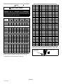
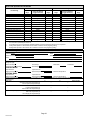
Table 8. Normal Operating Pressure − Liquid +10 and Vapor
+
5 PSIG*
IMPORTANT
Minor variations in these pressures may be
expected due to differences in installations.
Significant differences could mean that the system
is not properly charged or that a problem exists with
some component in the system.
5F (5C)**
XP19−024 XP19−036 XP19−048 XP19−060
Liq Vap Liq Vap Liq Vap Liq Vap
First Stage (Low Capacity)
40 (4.4) 314 100 316 99 350 98 365 96
50 (10) 334 120 334 117 367 111 388 112
Second Stage (High Capacity)
20 (−7.0) 304 68 294 64 314 60 346 60
30 (−1.0) 323 82 313 77 331 72 362 72
40 (4.4) 342 98 329 89 358 85 382 85
50 (10) 364 116 344 109 384 107 409 106
First Stage (Low Capacity)
65 (18.3) 226 152 230 148 210 136 234 135
75 (23.9) 262 151 267 150 242 138 274 137
85 (29.4) 304 152 309 153 286 140 314 142
95 (35.0) 351 155 355 155 328 142 361 147
105 (40.6) 400 158 404 157 374 144 413 147
115 (49.0) 454 161 460 159 426 146 470 149
Second Stage (High Capacity)
65 (18.3) 228 146 236 144 227 114 237 131
75 (23.9) 267 148 275 145 265 123 276 133
85 (29.4) 309 149 318 148 306 132 320 135
95 (35.0) 358 151 365 150 348 138 369 138
105 (40.6) 410 152 416 153 397 141 423 140
115 (49.0) 465 154 473 155 453 143 482 144
*These are most−popular−match−up pressures. Indoor match up,
indoor air quality, and indoor load cause pressures to vary.
**Temperature of the air entering the outside coil.
Table 9
. HFC−410A Temperature (°F) − Pressure (Psig)
°F Psig °F Psig °F Psig °F Psig
32 100.8 63 178.5 94 290.8 125 445.9
33 102.9 64 181.6 95 295.1 126 451.8
34 105.0 65 184.3 96 299.4 127 457.6
35 107.1 66 187.7 97 303.8 128 463.5
36 109.2 67 190.9 98 308.2 129 469.5
37 111.4 68 194.1 99 312.7 130 475.6
38 113.6 69 197.3 100 317.2 131 481.6
39 115.8 70 200.6 101 321.8 132 487.8
40 118.0 71 203.9 102 326.4 133 494.0
41 120.3 72 207.2 103 331.0 134 500.2
42 122.6 73 210.6 104 335.7 135 506.5
43 125.0 74 214.0 105 340.5 136 512.9
44 127.3 75 217.4 106 345.3 137 519.3
45 129.7 76 220.9 107 350.1 138 525.8
46 132.2 77 224.4 108 355.0 139 532.4
47 134.6 78 228.0 109 360.0 140 539.0
48 137.1 79 231.6 110 365.0 141 545.6
49 139.6 80 235.3 111 370.0 142 552.3
50 142.2 81 239.0 112 375.1 143 559.1
51 144.8 82 242.7 113 380.2 144 565.9
52 147.4 83 246.5 114 385.4 145 572.8
53 150.1 84 250.3 115 390.7 146 579.8
54 152.8 85 254.1 116 396.0 147 586.8
55 155.5 86 258.0 117 401.3 148 593.8
56 158.2 87 262.0 118 406.7 149 601.0
57 161.0 88 266.0 119 412.2 150 608.1
58 163.9 89 270.0 120 417.7 151 615.4
59 166.7 90 274.1 121 423.2 152 622.7
60 169.6 91 278.2 122 428.8 153 630.1
61 172.6 92 282.3 123 434.5 154 637.5
62 175.4 93 286.5 124 440.2 155 645.0
INSTALLING SERVICE VALVE CAPS
Disconnect gauge set and re−install all service valve caps.
INSTALL CAPS
OUTDOOR UNIT
SERVICE VALVE
Figure 33. Installing Service Valve Port Caps
Page is loading ...
Page is loading ...
Page is loading ...
Page is loading ...
Page is loading ...
Page is loading ...
Page is loading ...
Page is loading ...
Page is loading ...
Page is loading ...
Page is loading ...
Page is loading ...
-
 1
1
-
 2
2
-
 3
3
-
 4
4
-
 5
5
-
 6
6
-
 7
7
-
 8
8
-
 9
9
-
 10
10
-
 11
11
-
 12
12
-
 13
13
-
 14
14
-
 15
15
-
 16
16
-
 17
17
-
 18
18
-
 19
19
-
 20
20
-
 21
21
-
 22
22
-
 23
23
-
 24
24
-
 25
25
-
 26
26
-
 27
27
-
 28
28
-
 29
29
-
 30
30
-
 31
31
-
 32
32


Lennox Signature XP19-024 Installation Instructions Manual
- Category
- Split-system air conditioners
- Type
- Installation Instructions Manual
- This manual is also suitable for
Ask a question and I''ll find the answer in the document
Finding information in a document is now easier with AI
Related papers
-
Lennox 16HPX Series Units Installation guide
-
-
-
-
-
-
-
-
Lennox Merit 14HPX-060 Installation Instructions Manual
-
Other documents
-
Broan Liquid Line Solenoid Kits Installation guide
-
-
Whirlpool GOLD W4GH6 User manual
-
Scotsman Addition of a Head Pressure Control Valve to a Remote Condenser that does not have a Head Pressure Control - 17-3308-01 Operating instructions
-
Reznor R6GN Installation guide
-
Unbranded Compressor Lockout Board Accessory Kit Installation guide
-
Broan PSH4BG Installation guide
-
MasterCool 91200 Operating instructions
-
Trane 4TTM3018A1000A Installation guide
-
Intertherm Liquid Line Solenoid Kit for S3Q and T3Q Installation guide