1 HUSKYTOOLS.com
E109968- INSERT CUSTOMER WIRING INSTRUCTIONS
Please contact 1-888-43-HUSKY for further assistance.
230VAC Air Compressor Wiring Instructions
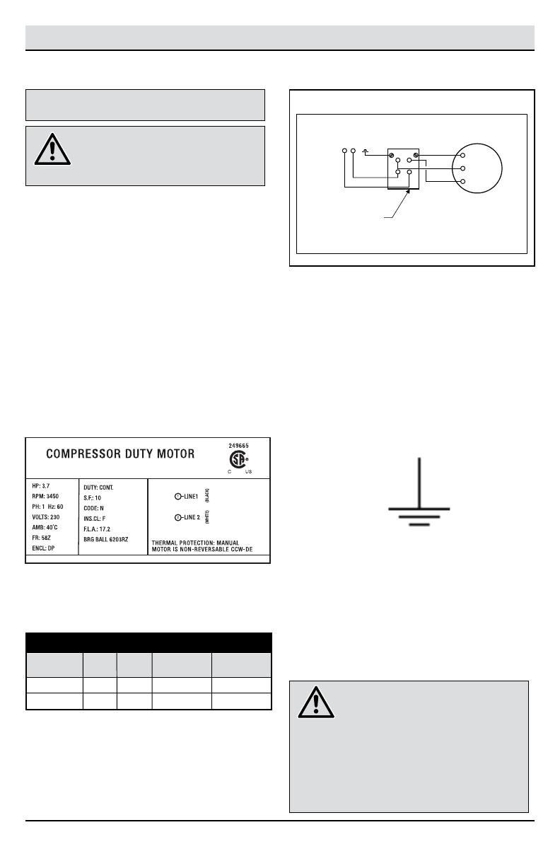
ELECTRICAL CONNECTIONS FOR
PERMANENTLY CONNECTED ELECTRIC
COMPRESSORS
NOTE: If using 208 volts single phase, make sure the
motor name plate states it is rated for 208 volts single
phase. 230 volt single phase motors do not work on 208
volts unless they have the 208 volt rating.
MOTOR LABEL
Ground Symbol
NOTICE: Electrical connections should only be performed by a
qualified electrician.
INCOMING POWER
T1
L1
G
G
L2
T2
FUSED DISCONNECT
OR CIRCUIT BREAKER
PRESSURE
SWITCH
MOTOR
230VAC SINGLE PHASE WIRING
C602H 3.7HP 17.2 10 - Gauge 6ft.
C801H/C803H 5HP 22 8 - Gauge 6ft.
Model HP AMPS 230V Allowable
Max Length
Single Phase
Wire Size Chart
GENERAL. The motor rating, as shown on the motor
nameplate, and power supply must have compatible
voltage, phase and hertz characteristics.
WIRE SIZE. The electrical wiring between the power
supply and electric motor varies according to motor
horsepower and other factors. Install adequately sized
power leads to protect against excessive voltage drop
during start-up. Refer to the applicable electric codes in
your area for information on selecting the proper wire
size and securing electrical connections. If you connect
additional electrical equipment to the same circuit,
consider the total electrical load when selecting the
proper wire size. DO NOT USE UNDERSIZE WIRE.
MINIMUM WIRE SIZE. (USE 75 DEGREE C COPPER WIRE)
Make sure voltage is correct with the motor wiring. Refer
to the motor label for the running HP rating. This will
determine the size wire needed. See example below.
Recommended wire sizes may be larger than the
minimum set up by the local ordinances. If so, the larger
wire size should be used to prevent excessive line
voltage drop. The additional wire cost is very small
compared with the cost of repairing or replacing a motor
electrically “starved” by the use of supply wires which
are too small. Also, if a lead wire longer than 6 ft. is
Compressors equipped with motor starters include a
ground terminal inside the starter enclosure. For
compressors with single-phase motors having thermal
overload protection and no motor starter, the ground
terminal is located inside the pressure switch. Ground
must be established with a grounding wire size according
to the voltage and minimum branch circuit requirements
printed on the compressor specifications decal. Ensure
good bare metal contact at all grounding connection
points, and ensure all connections are clean and tight.
WARNING: Electrical installation and
service must be performed by a
qualified electrician who is familiar with
all applicable electrical codes.
WARNING: Improper grounding can
result in electrical shock and can cause
severe injury or death.This product must
be connected to a grounded, metallic,
permanent wiring system or an
equipment-grounding terminal or lead.
All grounding must be performed by a
qualified electrician and comply with
applicable electric codes.
needed, consult a local electrician for alternative wiring
options.
FUSES. Refer to applicable local codes to determine the
proper fuse or circuit breaker rating required. When
selecting fuses, remember the momentary starting current
of an electric motor is greater than its full load current.
Time delay or “slow-blow” fuses are recommended.
GROUNDING. In the event of an electrical short circuit,
grounding reduces the risk of electric shock by providing
an escape wire for the electric current. Ground terminals
are identified with a ground symboland/or the letters “G”,
“GR” or “PE” (Potential Earth).

