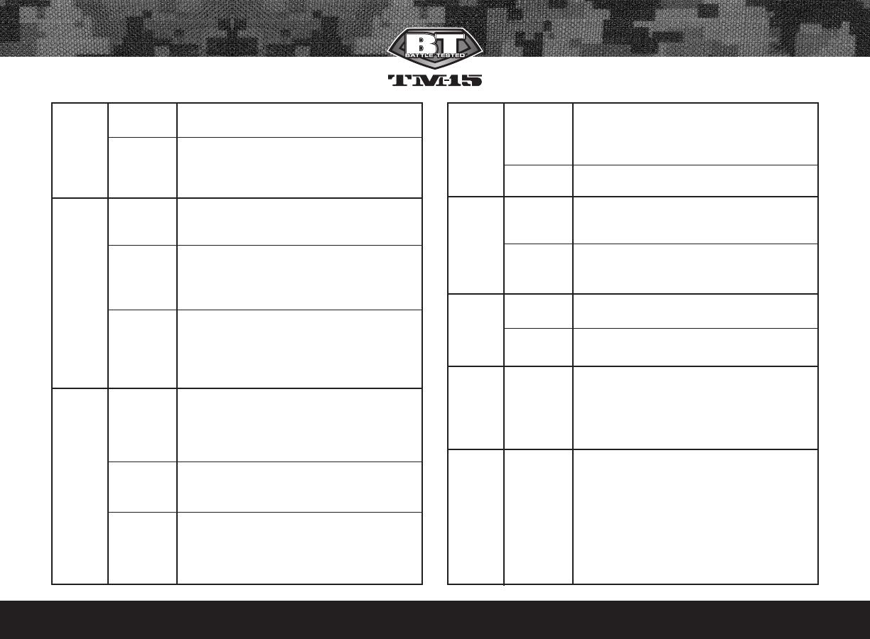
BT / Empire Battle Tested TM-15 Owner's manual

Type
Owner's manual
OWNERS MANUAL
BTPAINTBALL.COM
BT_TM-15_Manual.qxp 6/17/09 5:23 PM Page C
BTPAINTBALL.COM
CONTENTS Page
1. Rules for Safe Marker Handling 1
2. Introduction and Specifications 1
3. Battery Replacement and Life Indicator 1
4. Compressed Air/Nitrogen Supply 2
5. Basic Operation 2
6. Firing the TM-15 4
7. Break Beam Eyes Operation 4
8. Unloading the TM-15 5
9. Regulator and Velocity Adjustments 5
10. Programming 6
11. Setting Functions 7
12. Trigger Adjustments 9
13. General Maintenance 10
14. Assembly/Disassembly Instructions 11
15. Storage and Transportation 14
16. Troubleshooting Guide 14
17. Diagrams and Parts List 17
WARRANTY (Inside Back Cover)
NEITHER BT PAINTBALL DESIGNS, INC. NOR ANY OF ITS PRODUCTS ARE AFFILIATED WITH TIPPMANN SPORTS, LLC.
For manuals and warranty details, go to:
paintballsolutions.com
For manuals in other languages, (where appli-
cable), go to:paintballsolutions.com
©2009 BT Paintball Designs, Inc. The BT Shield,
“Battle Tested” and “TM-15” are trademarks of
BT Paintball Designs, Inc. All rights reserved.
BT_TM-15_Manual.qxp 6/17/09 5:23 PM Page D
BTPAINTBALL.COM
1
1. Rules for Safe Marker Handling
IMPORTANT: Never carry your TM-15 uncased when not on a playing
field. The non-playing public and law enforcement personnel may not be
able to distinguish between a paintball marker and firearm. For your own
safety and to protect the image of the sport, always carry your TM-15 in
a suitable marker case or in the box it came in.
Treat every marker as if it were loaded.
Never look down the barrel of a paintball marker.
Keep your finger OFF the trigger until ready to shoot.
Never point the marker at anything you don’t wish to shoot.
Keep the marker on “safe” until ready to shoot.
Keep the barrel blocking device in/on the marker’s barrel when not shooting.
Always remove paintballs and air source before disassembly.
After removing air source, point marker in safe direction and discharge
until marker is degassed.
Store the marker unloaded and degassed in a secure place.
Follow warnings listed on the air source for handling and storage.
Do not shoot at fragile objects such as windows.
Every person within range must wear eye, face, and ear protection designed
specifically to stop paintballs and meeting ASTM standard F1776.
Always measure your marker’s velocity before playing paintball and
never shoot at velocities in excess of 91.44 meters (300 feet-per-second).
READ OWNERS MANUAL BEFORE USING.
2. Introduction and Specifications
Congratulations on your selection of the TM-15 paintball marker. The TM-
15 is made to provide you with many years of reliable performance. We are
honored that you have chosen the TM-15 as your marker of choice and
hope you enjoy using this high quality product.
The patented Valve design, Slip Stream™ Solenoid, Hall Effect Sensor
Trigger, and Four Position Selector Switch set new standards for marker tech-
nology. The TM-15 is precision engineered from magnesium alloy, aircraft-
grade aluminum, and composite materials. We expect you to play hard and
play frequently and the TM-15 was built with this in mind.
The TM-15 operates on low pressure. The main operating pressure is
180–200 PSI. The pressure can be nominally adjusted and monitored visually
via the gauge on the bottomline regulator. There is no secondary regulator
to worry about
.
TTMM--1155 SSppeecciiffiiccaattiioonnss
Model- TM-15
Barrel- 14" Ported Barrel
Caliber- .68
Action- Semi Auto, PSP Burst, and NXL Full Auto
Air source- Compressed Air
Battery- One 9-Volt (Alkaline Only)
Cycle Rate- Up to 20 BPS
Shell Material- Magnesium Alloy
Accuracy Range- 150ft +
IInncclluuddeedd wwiitthh yyoouurr TTMM--1155
- 14" Barrel (.691 bore)
- Allen Wrenches
- Spare Parts Kit
- Barrel Blocking Device
- One 9-Volt Battery
- Manual
- One BT Rip-Clip
Adapter & Adapter Screw Kit, for use with the TM Rip-
Clip
only. (TM Rip-Clip
not included)
3. Battery Replacement and Life Indicator
The TM-15 requires a single 9-volt alkaline battery as the electronic power
source. The use of long life batteries is recommended. The battery is installed
by removing the magazine and inserting a 9-Volt battery into the magazine.
BT_TM-15_Manual.qxp 6/17/09 5:23 PM Page 1
BTPAINTBALL.COM
2
To remove the magazine, press in the magazine release button, which is
located on the right side of the TM-15. While pressing the release button,
pull the magazine down and out of the body and then insert a 9-volt bat-
tery following the polarity markings on the side of the magazine. (Fig. 1.1)
The TM-15 also has a battery life
indicator. When in a firing mode
(F1, F2, and F3), if the LED flash-
es green then the battery is
good, if the LED is orange the
battery is fairly depleted and you
should change batteries soon, or
if the LED is red then the battery
should be replaced immediately.
Note: Some rechargeable batteries might be too large for the TM-15
magazine battery compartment. If they do not fit, please do not force
them into the magazine.
4. Compressed Air/Nitrogen Supply
The TM-15 is designed to work with compressed air/nitrogen only. Do not
use CO
2, as it will damage your TM-15.
Consult the Dealer where you purchased your TM-15, or a recognized and
competent air smith, for instruction in the safe handling of compressed-air
cylinders before purchasing or connecting one to your TM-15.
The TM-15 utilizes a fully functional regulator at the bottom of the grip
frame that doubles as an ASA (Air Source Adapter) or Receiver for a stan-
dard threaded pre-set output compressed air system. It is strongly recom-
mended that a very high-flow “low-pressure” (350–450 psi) fixed-output sys-
tem is utilized as an air source for your TM-15. Using a “high-pressure” out-
put compressed air tank is acceptable. If you are using an adjustable out-
put regulator system, the output pressure should be between 400–500 psi.
Before pressurizing your TM-15:
Check to make sure that you and anyone within range are wearing eye
protection designed specifically for paintball.
• Double check that all screws are tightened and no parts are loose before
installing your tank.
• Ensure you have a barrel plug, barrel cover, or other specifically designed
barrel-blocking device in place.
• Make sure there are no paintballs in the marker.
The Power should be OFF and the Selector switch should be set to the
Safety position.
Air can now be applied; the marker will become pressurized.
Notes:
• Remember compressed air or nitrogen systems can be extremely dan-
gerous if misused or improperly handled. Use only cylinders meeting
D.O.T. or regionally defined specifications.
Never disassemble your tank or tank regulator. Only a qualified and
trained technician should perform work on your tank and tank regulator.
Never add any lubricants or greases into the fill adapter on your tank
regulator or into the TM-15 regulator.
5. Basic Operation
Safety and safe marker handling are the most important aspects of paint-
ball sports. Please practice each of the following steps with an unloaded
marker before attempting to charge your marker with compressed air
and paintballs.
Do not install compressed air or load paintballs into your TM-15 until you
feel completely confident with your ability to handle your TM-15 safely.
Fig 1.1
Fig 1.1
BT_TM-15_Manual.qxp 6/17/09 5:23 PM Page 2
BTPAINTBALL.COM
3
Keep your finger out of the trigger guard and away from the trigger;
point the muzzle of the marker in a safe direction at all times. Keep the
marker turned OFF when not in use. The TM-15 uses a power switch
and a selector switch for its safety devices.
• Always keep your TM-15 pointed in a safe direction. Always use a barrel
plug or barrel blocking device. Always use paintball specific eye protec-
tion meeting or exceeding ASTM standards in any areas where paintball
markers may be discharged.
• Remember that the ultimate safety device is you, the operator.
Feed Elbow Installation
Seat the feed elbow onto
the narrow section of the
top picatinny rail: about 1"
forward of the feed hole on
the right side of the
marker (Fig. 1.2). Then push
and hold in the latch button while sliding the feed elbow toward the rear
of the marker (Fig. 1.3). Just before the feed elbow covers the feed hole
in the right side of the marker, release the latch button and continue slid-
ing the feed elbow until the latch locks into the rail slot. When done cor-
rectly, the feed elbow will now be unable to slide forward or backward
without holding in the latch button, and the feed hole in the right side
shell will not be visible from the sides of the feed elbow.
Barrel Installation
Make sure marker is degassed, hopper removed, no paintballs in the feed
elbow or breech, and the TM-15 is turned off.
While pointing marker in a safe direction, place the threaded end of the
barrel into the front opening of the marker body.
• Turn the barrel clockwise until it stops (do not over tighten).
• Install a barrel blocking device. This can be a barrel plug or other such
device that prevents the accidental discharge of paintballs.
Switching on your TM-15
Warning: Before switching on your TM-15, make sure it is pointed in a safe
direction. Always use a barrel plug or barrel blocking device. Remember
that the ultimate safety device is you, the operator.
To switch the TM-15 on, set the selector switch to the (S) safety position.
The TM-15 will not turn on unless the selector is in the safety position.
Locate the power button on the left side of the marker. Push and hold the
power button for 2 seconds and the LED light will turn green and then to
red. Release the button and the LED will remain red.
The TM-15 will now be on and in the (S) safety position. To make the TM-15 live,
move the selector switch to the F1, F2, or F3 positions. Do not move the selec-
tor switch to a firing position until you are ready to safely use the marker.
Switching OFF your TM-15
Move the Selector Switch to the (S) safety position, push and hold the
power button for 2 seconds, and the LED will turn from red to green.
Release the power button and the TM-15 will switch off.
Selector Switch
The TM-15 comes equipped with a four-position selector switch which comes
factory set in the recreational firing mode setting. Move the selector from posi-
tion (S) safety, to positions (F1, F2, and F3) to change into a firing mode (Fig 1.4).
Selector Positions
Safety ---------------------------------
Semi-Auto ------------------------
PSP Ramping -------------------
NXL Full Auto ------------------
Automatic OFF feature
The TM-15 also has an “Automatic OFF” feature. If you accidentally leave
your TM-15 powered up, it will shut itself off after approximately 1 hour
of inactivity.
Fig 1.3Fig 1.2
Fig 1.4
BT_TM-15_Manual.qxp 6/17/09 5:23 PM Page 3
BTPAINTBALL.COM
4
Eye Function
The TM-15 board is pre-programmed to activate the eye system each
time the marker is powered up. See Section 7 (Break Beam Eyes Oper-
ation) for more details.
Installing a Loader and Paintballs
The TM-15 comes equipped to accept 1.03" (outer dimension) standard-
gravity feed loaders as well as most agitating and force-feed loaders. Fit
the loader directly into the feed elbow. It might be necessary to adjust the
feed elbow clamping screw to your loader.
The TM-15 uses .68 caliber, water-soluble paintballs, readily available at
paintball pro-shops, commercial playing fields, and many sporting goods
stores. The paintballs are fed from the loader through the feed elbow and
into the breech of the marker.
Stock Adjustment
The TM-15 stock can be
adjusted by depressing the
stock adjustment lever.
Adjust the stock’s length by
pulling or pushing on the
back of the stock (Fig. 1.5).
Sight Adjustment
The front and rear sights
can be moved anywhere along the top picatinny rail. They can also be
folded down or completely removed when not being used. To adjust or
remove the sights, loosen the screw on the base of the sight and either
relocate it or remove it.
6. Firing the TM-15
Warning: Always keep your TM-15 pointed in a safe direction! Everyone
within firing range should always use paintball approved eye and face
protection in the presence of live paintball markers.
To turn the TM-15 on, set the selector switch to the (S) safety position, push
and hold the power button for 2 seconds, and the LED light will turn green
and then red and then release the button. Your TM-15 is now powered on
and in the safety position
Firing Your TM-15
Place the empty loader onto the marker.
Be sure that it is securely mounted in place.
Apply the compressed gas, pressurizing the marker.
Put the paintballs into the loader.
Remove the barrel plug, sock, or barrel-blocking device.
Aim the TM-15 in a safe direction.
Turn the TM-15 on.
Move the selector switch to the desired firing mode.
Aim the TM-15 at the target.
Place your finger on the trigger.
Pull the trigger with a smooth squeezing motion.
Note: When the game you are playing is over, remember to place the
barrel-blocking device onto your barrel and move the selector to the
safety position.
7. Break Beam Eyes Operation
The TM-15 uses a break beam eye system to determine the absence or
presence of a ball for the purposes of reduced paint breakage and opti-
mum rates of fire. The TM-15 board is pre-programmed to activate the
eye system each time the marker is powered up.
Fig 1.5
BT_TM-15_Manual.qxp 6/17/09 5:23 PM Page 4
BTPAINTBALL.COM
5
To turn the eyes off, ensure that there are no paintballs in the markers
breech or feed elbow and make sure the marker is switched off. While
pulling and holding the trigger, turn the marker on. When the selector is
switched to a firing mode, a quick double blinking green LED will indicate
that the eye system has been deactivated. To turn the eyes back on,
simply press the power button one time quickly.
Notes:
When the eyes are on, a slow consistent single-flashing green LED
indicates that no ball is in the breech and a rapid flashing green LED
indicates that there is a ball in the breech.
For optimal performance of the TM-15 eyes, keep the inside of the
TM-15 breech clean and clear of broken paint, paint residue, or other
debris.
Although the eyes can be cleaned via cleaning the breech of the TM-15
marker, if the eyes need to be accessed, please follow the steps outlined
in the Disassembly/Assembly section of this manual.
8. Unloading the TM-15
Warning: Always keep your TM-15 pointed in a safe direction and always
keep your protective eye, face, and ear wear on until marker is complete-
ly unloaded and safe.
Be sure your finger is away from the trigger area.
Place the barrel plug, sock, or barrel-blocking device into the end of the
barrel.
Move the selector switch to the (S) safety position.
Turn the TM-15 off by pressing and holding the power button. The LED
will change from red to green, once it changes to green, release the
button. Observe the light to make sure it is no longer lit.
Remove your pressurized gas source by slowly and carefully
unscrewing it.
If you are using an electronic loader make sure loader is completely
turned off.
Slightly tilt the marker so that the loader is lower than the body.
Remove the loader by releasing the clamp and spinning it in a
clockwise direction and gently pulling it.
Read the pressure gauge and make sure the pressure reads 0 psi.
Do not look down the barrel but look down the feed neck to make sure
there are no paintballs in the breech.
Remove the barrel from the marker.
Make sure there are no more paintballs remaining in the barrel.
9. Regulator and Velocity Adjustment
The TM-15 utilizes a Bottom-line regulator that doubles as an ASA
Adapter/Receiver for a standard threaded pre-set output compressed air
systems or remote hose. This unique regulator system channels air
through the air transfer tube, eliminating the need for external macro line
and fittings. The TM-15 bottom-line regulator controls the amount of air
pressure going from your compressed air system into the marker.
The TM-15 regulator should be factory pre-set at about 200 psi, as this is
the best operating pressure for proper marker operation. However, if over
time you do need to adjust the pressure, use the Regulator Adjuster Screw
on the front of your TM-15 bottom-line regulator.
Regulator Adjustment
Note: Do not use this to adjust the velocity of the marker.
If adjustments are needed, use a 3/16"
Allen wrench and insert it into the regu-
lator adjustment screw. This is located in
the front of the regulator (Fig. 1.6).
To Increase Output Pressure- Turn the reg-
ulator’s adjustment screw clockwise.
To Decrease Output Pressure- Turn the
regulator’s adjustment screw counter-clockwise.
Fig 1.6
BT_TM-15_Manual.qxp 6/17/09 5:23 PM Page 5
BTPAINTBALL.COM
6
Notes:
• Always watch the gauge as you are adjusting the pressure.
• The bottomline regulator should not be disassembled.
• Never set the regulator above 200 psi.
Adjusting Velocity- At the back of the TM-15 internal body is the bolt
guide cap. The holes in the bolt guide cap serve as your velocity adjuster.
Confirm that the pressure on your TM-15 bottom-line regulator is at 200
PSI.
You can access the velocity adjuster by sliding the velocity adjustment
cover forward and inserting a 7/64" Allen wrench into the bolt guide cap
thru the bottom of the marker. Then you can increase or decrease the
velocity on your TM-15 by tightening or loosening the bolt guide cap, using
the included 7/64" inch Allen wrench.
To Increase Velocity- Unscrew or loosen the
velocity adjustment screw by turning it
counter clockwise. Rotate the velocity
adjustment screw in small increments, stop-
ping between slight turns to test velocity,
until desired velocity is achieved. Do not
back the adjuster out too far. Stop if you
hear an air leak, and adjust back in a 1/4
turn (Fig. 1.7). A paintball specific radar chronograph should be used to
accurately measure your velocity.
To Decrease Velocity- Tighten or screw-in the velocity adjustment screw
by turning it clockwise. Rotate the velocity adjustment screw clockwise in
small increments (1/4 turn or less), stopping between slight turns to test
velocity, until desired velocity is achieved. A paintball specific radar
chronograph should be used to accurately measure your velocity.
Notes:
•This marker was designed with safety and safety standards in mind. If
you attempt to shoot paintballs at a higher velocity than established
safety standards, the marker may not function properly.
This marker is not designed to shoot above the safety limits established
by Industry Standards, but under certain conditions it may. It is there-
fore important to check the velocity before using your TM-15.
The velocity is not adjusted by inserting the Allen wrench into the velocity
adjuster and rotating the Allen wrench, but by using the Allen wrench as
a handle to rotate the velocity adjuster.
10. Programming
Note: In this section, you will see the phrase "Cycle the Selector Switch".
To cycle the selector switch, move the selector switch from the (S) position
to the (F3) position and then back to the (S) position.
Tournament Lock On/Off
The TM-15 comes with a tournament lock which will lock your marker into
the firing mode currently selected. The Tournament lock button is
accessed thru a small hole just in front of the trigger. The TM-15 must be
turned off to change the tournament lock setting.
Carefully insert the long side of the 3/32" Allen wrench into the hole on the
trigger guard and then into the hole on the
body and then gently press the tournament lock
button to show the current status of the tourna-
ment lock (Fig. 1.8).
If the LED blinks green, the tournament lock
is on.
If the LED blinks red, the tournament lock is
off.
Fig 1.7
Fig 1.8
BT_TM-15_Manual.qxp 6/17/09 5:23 PM Page 6
To change the tournament lock, press the button once to display the cur-
rent status, then press it again within 1 second and the LED will blink the
new status.
Note: The tournament lock button is part of the markers circuit board.
Only use light pressure when pressing the button.
To Enter Programming Mode- The TM-15 must be OFF and the tourna-
ment lock must be off to begin managing the functions. While the TM-15
is off, with the selector switch in the safety (S) position, press and hold the
power button, cycle the selector switch, then release the power button to
enter programming mode. If done correctly the LED will change to a solid
red, which is the firing mode function.
Once in programming mode, with selector switch in the (S) position, each
time the power button is pushed you will cycle to the next Function and
the LED will change to a specific color per the descriptions below.
Function’s current value- To view a function’s current value, advance to
the function you wish to check using the power button. Then simply pull
and release the trigger quickly to view its current value by observing the
number of flashes.
Changing a Function’s Value- Once you have selected the function you wish to
change, move the selector switch to the (F1) position to increase the value or to
the (F2) position to decrease the value. Each time the trigger is pulled it will increase
or decrease the function’s value by one. If the selector switch is in the (F3) position,
a single trigger pull will return a function value to its default setting. Once a func-
tion’s value is changed, move the selector switch to the the (S) safety position.
To check the function’s new value, simply pull and release the trigger once while
the selector is in the safety (S) position and the LED will flash the new value. At this
point, you can select a different function to change or exit programming mode.
Exiting Programming Mode- push and hold the power button, cycle the
selector switch, and then release the power button.
11. Setting Functions
Firing Modes
Firing modes will be indicated by a solid red LED. The default firing mode
is the recreational mode (value 5).
Note: Selector position (0) is used as a Safety in all Modes.
Value 1: Semi-Auto – One shot per trigger pull.
Value 2: PSP – The TM-15 will operate in semi-auto mode for the first 3
safety shots; then if the user maintains at least one pull per a second, the
TM-15 will fire “x” number of shots per pull and release of the trigger as
defined by function 6 (burst shots) at the rate of fire defined by function 2.
No trigger pull within one second of the last pull will reset the mode and the
user must fire three more safety shots to continue burst shots.
BTPAINTBALL.COM
7
Function LED Color Default Value Range
1 Firing Mode Solid Red 5 1-5
2 ROF
(rate-of-fire) Solid Green 11 1-25
3 Dwell Solid Orange 28 1-45
4 BIP
(ball in place) Flashing Red 10 1-40
5 Ramping Point Flashing Green 4 3-9
6 Burst Shots Flashing Orange 3 3-9
Selector Switch Position in Programming Mode
S Cycle to Next Function / Read a Current Value
F1 Increase a Functions Value
F2 Decrease a Functions Value
F3 Returns a Function to Factory Default
BT_TM-15_Manual.qxp 6/17/09 5:23 PM Page 7
BTPAINTBALL.COM
8
Value 3: Full-Auto/NXL – The TM-15 will operate in semi-auto mode for
the first 3 safety shots; then pull and hold trigger on the 4th shot, and the
TM-15 will fire full-auto at the rate of fire value in function 2, which is
defaulted to 13 shots per second for this mode.
Value 4: Ramping/Millennium – The TM-15 will operate in semi-auto
mode until player achieves the minimum trigger pull as defined by the
ramping point value in function 5, which is defaulted to 6 trigger pulls per
second for this mode. At that point, and as long as 6 trigger pulls per sec-
ond are maintained, the TM-15 will ramp to the rate of fire value in func-
tion 2, which is defaulted to 12 shots per second for this mode.
Value 5: Recreational Mode - Selector Switch Position (1) - Standard
Selector Switch Position (F1) - Semi-automatic; see value 1.
Selector Switch Position (F2) – PSP; see value 2.
Selector Switch the (F3) Position - NXL full auto; see value 3.
Notes:
If you activate the tournament lock on your TM-15 while in recreation-
al mode, all three firing modes will still be active.
• It is possible to raise or lower both the rate of fire and ramping point
values if rules change.
Selector the (S) position is used as a safety in all firing modes.
Max Rate of Fire (ROF)
Max Rate of Fire (ROF) will be indicated by a solid green LED.
The default Max ROF is 6 flashes (13 BPS).
Dwell Setting
Dwell Setting will be indicated by a solid orange LED.
The Dwell setting determines how long the Slip Stream™ Solenoid is
open. The Dwell is defaulted at setting 28 and is adjustable from 1–45.
Note: If the Dwell Setting is adjusted too high or low, the TM-15 will not
function correctly.
Flashes/ROF Flashes/ROF Flashes/ROF
1 Flash = 8 BPS
2 Flash = 8.5 BPS
3 Flash = 9 BPS
4 Flash = 9.5 BPS
5 Flash = 10 BPS
6 Flash = 10.5 BPS
7 Flash = 11 BPS
8 Flash = 11.5 BPS
9 Flash = 12 BPS
10 Flash = 12.5 BPS
11 Flash = 13 BPS
12 Flash = 13.5 BPS
13 Flash = 14 BPS
14 Flash = 14.5 BPS
15 Flash = 15 BPS
16 Flash = 15.5 BPS
17 Flash = 16 BPS
18 Flash = 16.5 BPS
19 Flash = 17 BPS
20 Flash = 17.5 BPS
21 Flash = 18 BPS
22 Flash = 18.5 BPS
23 Flash = 19 BPS
24 Flash = 19.5 BPS
25 Flash = 20 BPS
Firing Modes
Value Selector Position Mode
F1 Semi-Auto
1 F2 Semi-Auto
F3 Semi-Auto
F1 PSP
2 F2 PSP
F3 PSP
F1 NXL Full-Auto
3 F2 NXL Full-Auto
F3 NXL Full-Auto
F1 Millennium Ramping
4 F2 Millennium Ramping
F3 Millennium Ramping
F1 Semi-Auto
5 F2 PSP
F3 NXL Full-Auto
BT_TM-15_Manual.qxp 6/17/09 5:23 PM Page 8
BTPAINTBALL.COM
9
Ball in Place Delay (BIP)
Ball in Place Delay (BIP) will be indicated by a flashing red LED.
The BIP is defaulted at 10 ms (each Flash = 1 millisecond). BIP is
adjustable from 1–40 milliseconds.
Note: If you are not using a force-feed loader, it is recommended that you
use a higher BIP setting.
Ramping Point
Ramping Point will be indicated by a flashing green LED.
The default ramping point is 4 (4.5 BPS). Ramping Point is adjustable from
4–9.5 BPS. Please see chart for corresponding flashes and BPS settings.
Burst Shots
Burst Shots will be indicated by a flashing orange LED.
The Burst shot value is defaulted to 3 and is adjustable from (3–5).
Programming Example: If you are in the default recreational firing mode
and want to go to semi-auto firing mode. Push and hold the power button,
cycle the selector switch, then release the power button and the LED will be
a solid red. Move the selector switch to position (F2) which will decrease the
value and pull the trigger four times and then move the selector switch back
to the (S) position. Pull the trigger while in the (S) position to check the
changed value. The LED will now flash 1 time, to show that the firing mode
has been changed to semi-auto.
Factory Board Reset
To reset all the functions to the defaults, turn off your TM-15, then carefully
insert the long side of the 3/32" Allen wrench into the tournament lock
access hole and then gently press the button in for 5 seconds. Once an
orange LED flashes to confirm the reset, release the button.
12. Trigger Adjustments
The TM-15 features a Hall Effect Sensor Trigger. There is no trigger switch
to worry about, clog with paint, or break. The TM-15 trigger can be adjust-
ed by the four set screws in the trigger.
When a trigger pull is recognized, the LED will quickly flash a dim Red for
each trigger pull. If no trigger pull is recognized, the LED flashes normal-
ly based on the status of the eyes and battery power level. If the trigger is
held in, the dim red LED will stay illuminated.
Before making any trigger adjustments, de-gas the TM-15, make sure the
gauge reads 0 psi, then switch ON the TM-15 with eyes turned off to
easily monitor the current activation point.
You will notice four (4) set screws in your trigger (Fig. 1.9). These can be
adjusted with a 1/16" Allen wrench. Make small adjustments and check that
the trigger is activating the solenoid.
The first (1) set screw adjusts the
trigger activation point. For best
results, the activation point should
be set right in the middle of the
total trigger movement from front
to back.
6 Flashes = 3 BPS
7 Flashes = 3.5 BPS
8 Flashes = 4 BPS
9 Flashes = 4.5 BPS
10 Flashes = 5 BPS
11 Flashes = 5.5 BPS
12 Flashes = 6 BPS
13 Flashes = 6.5BPS
14 Flashes = 7 BPS
15 Flashes = 7.5 BPS
16 Flashes = 8 BPS
17 Flashes = 8.5 BPS
18 Flashes = 9 BPS
Ramping Point
Flashes/PTR (Pulls to Ramp)
1
2
3
4
Fig 1.9
BT_TM-15_Manual.qxp 6/17/09 5:23 PM Page 9
BTPAINTBALL.COM
10
• The Second (2) set screw adjusts forward movement, and forward
stop point.
The Third (3) set adjusts the trigger return spring tension. Turn it clock-
wise to increase the spring tension and counter clockwise to decrease
the spring tension.
The (4) Fourth set screw adjusts the rear movement range, and rear
stop point.
Notes:
If any of the set screws are over adjusted in any direction the TM-15 may
not fire.
• If the trigger travel is adjusted too short, the TM-15 may fire on its own,
repeatedly and/or uncontrollably.
13. General Maintenance
CAUTION: Before attempting to perform any maintenance operations,
make sure that all paintballs and propellant sources have been removed
from the marker and that the regulator gauge reads 0 psi. Install a bar-
rel blocking device, move the selector switch to the off position and push
power button and hold for over 2 seconds until the LED light changes
from Red to Green, and keep the TM-15 power off.
Keep your TM-15 clean and lubricated to eliminate the friction that would
prevent reliable operation. Clean and lube the marker before each use,
and do not put it away dirty. Do not use oils made for paintball markers,
real firearms or pneumatic tools, do not use oils at all. Do not use petro-
leum-based lubricants in the lubrication of this marker. Teflon or silicon
(non-spray only) lubricants designed for use on o-rings may be used for
lubrication for the bolt, bolt guide and poppet area only. Only use grease
supplied with your TM-15.
Keep your TM-15 clean and lubricated to eliminate the friction that would
prevent reliable operation. It is recommended that you clean and lube the
marker before each use.
Do not use oil or petroleum-based lubricants in the lubrication of this mark-
er. Teflon or silicon (non-spray only) lubricants designed for use on O-Rings
may be used for lubrication for the bolt, bolt guide and poppet area only.
Dow 33 or the include grease is recommended.
Internal Cleaning & Greasing
The TM-15 is designed to allow you to access the bolt guide assembly
without separating the shells. On the back of the TM-15, there is a
removable panel which is taken off to allow easy access to the bolt guide
assembly for cleaning and maintenance.
Remove the two panel screws, using a 7/64" Allen wrench and lift the
panel off.
Lift out the stock assembly, stock cover, and the velocity adjuster cover.
Once the panel is removed, use a 1/8" Allen wrench to remove the bolt
guide retention screw.
• Insert a 7/64" Allen wrench into one of the velocity adjuster holes or
into the slot and pull the bolt assembly straight back. Stop when it hits
the shell.
• Rotate the bolt guide counter clockwise, about
1
/
4
turn. This will allow
you to pull the bolt guide assembly out.
Once the bolt guide assembly is out, use a BT battle swab to clean the
inside of the body, and then clean and re-grease the bolt guide assem-
bly as described in Section 14.
To install the bolt guide assembly, reverse the above steps, making sure
the stock, stock cover, and velocity adjuster cover are sitting in the right
side shell correctly. Also check that the bolt guide retention screw is all the
way in, before putting the removable panel back on.
External Cleaning
Use a clean cloth, dampened with water, to clean the outside of the
BT_TM-15_Manual.qxp 6/17/09 5:23 PM Page 10
BTPAINTBALL.COM
11
TM-15. Do not use any chemicals, as you may damage the protective finish.
If a full cleaning is needed, we recommend that you fully disassemble the
TM-15; doing so will allow you to rinse the shells with hot water to remove
dirt and paint buildup.
Warning: Do not rinse the TM-15 under water without fully disassembling
the marker, as you may damage the markers electronics.
14. Assembly/Disassembly Instructions
CAUTION: Before attempting to perform any marker disassembly, make
sure that all paintballs and propellant sources have been removed from
the marker and that the regulator gauge reads 0 psi. Install a barrel-
blocking device, move the selector switch to the safety (S) position, and
make sure the TM-15 is turned off.
Disassembly Tips
•Make sure you have a clean area to work on your marker.
Do not remove the air transfer tube from the body and regulator; these
parts are assembled tightly at the factory to prevent leaks.
When separating the shell for the first time, locate the trigger and trig-
ger spring, notice their position for easy reassembly.
Make sure the main spring is installed correctly on the bolt, as it needs
to be installed in the right direction.
After reassembling the TM-15 recheck your trigger activation settings.
Visit PaintballSolutions.com for additional information.
Barrel
It is recommended that the barrel be removed before and other mainte-
nance or disassembly is performed. Simply turn the barrel counter clockwise
to remove. Use warm water and a barrel cleaning device to keep the barrel
in top condition.
Feed Elbow
To remove the feed elbow, push and hold in the latch button while sliding
the feed elbow forward and lift off the elbow when it reaches the narrow
section of the top rail. The Feed elbow does not slide off the front of the rail.
Note: Make sure that when the feed elbow is reinstalled it lines up with
the hole on the right side of the shell.
Magazine
To remove the magazine, press in the magazine release button located on
the right side of the TM-15 and pull the magazine down and out of the shell.
Front and Rear Sights
Using a 7/64" Allen wrench, loosen the screws at the base of both the
front and rear sights, and remove.
Removable Shell Panel
The removable shell panel can be removed to access the internal assem-
bly for basic cleaning and maintenance by removing the two panel
screws with a 7/64" Allen wrench and then lifting the panel off.
Stock Assembly
The stock assembly can be removed from the shell once the removable
shell panel has been removed.
Grips
Using a 5/64" Allen wrench, remove the four 6-32 button head screws holding
the grips in place. Notice that the lower screws are longer than the top grip screws.
Selector Arm
It is not necessary to remove the selector arm when dissembling the
TM-15. Using a 1/16" Allen wrench, remove the flat head screw which
holds the selector arm to the selector shaft.
BT_TM-15_Manual.qxp 6/17/09 5:23 PM Page 11
BTPAINTBALL.COM
12
Note: The selector arm is keyed into the selector shaft. Make sure they are
aligned before reinstalling the selector arm screw.
Magazine Release Assembly
Remove the magazine release screw, using a 5/64" Allen wrench. Lift
the spring cap and spring out of the right side shell; and then push the
magazine release arm out of the left side shell.
Separating Shell
Once the parts above have been removed, the shell can now be
separated. The shell is separated by loosening all the shell screws.
• Using a 7/64" Allen wrench, loosen all the socket head screws in the
left side shell.
• Also loosen the two flat head screws, located under the grips with a
5/64" Allen wrench.
The left side shell can now be separated from the right, by lifting it off.
Note: It is not necessary to remove the picatinny side rails to separate the shells.
Trigger
The trigger can be removed by simply lifting it out of the right side shell.
When reinstalling it, make sure the trigger spring is seated correctly. See
the picture below for correct installation.
Trigger spring
The trigger spring serves as a dual purpose
spring. It holds the selector switch in position
and gives the trigger a spring return. (See Fig.
2.0 for correct installation).
Selector Shaft
The selector shaft sits in the right side shell on a post and connects to the
selector switch arm, when fully assembled. You will notice, on one side of the
shaft four keys that sit into the trigger spring. Make sure these keys line up
before putting the shell back together.
Removing the Body from the Shell
Warning: Before removing the body assembly from the shell it will be nec-
essary to unplug the battery harness or lift out the battery harness holder.
• Separate the shells as described.
Remove the two body retaining screws using a 7/64" Allen wrench.
• Lift the body assembly from the right side shell
Removal, Installation and Cleaning of Ball Detents
Use a 5/64" Allen wrench and turn counter-clockwise to remove the
ball detent assembly.
Clean the detents with a damp cloth and apply a small amount of
grease to the outer sides of the detents if sticking is an issue.
• Installation is the reverse of the removal. Do not over tighten the ball
detent covers!
Note: Be careful not to lose any of the detent parts as they are small.
Removal of Bolt Guide Assembly
Caution: Make sure the TM-15 is completely empty of air before
removing the Bolt Guide Assembly.
Either take off the removable panel or separate the shells as described.
Using a 1/8" Allen wrench, insert it
into the rear retention screw, turn the
Allen wrench counter-clockwise and
completely remove the screw (Fig. 2.1).
• Insert a 7/64" Allen wrench into one
of the velocity adjuster holes or into
the slot and pull the bolt assembly
straight back. If the assembly does
Fig 2.0
Fig 2.1
BT_TM-15_Manual.qxp 6/17/09 5:23 PM Page 12
BTPAINTBALL.COM
13
not easily slide out, insert a BT barrel swab into the front of the body
and push out the bolt and bolt guide assembly.
Note: You can remove the bolt guide assembly for maintenance and
cleaning by taking off the removable shell panel only. It is not necessary
to separate the shells.
Maintenance of Bolt and Bolt Guide
Inspect the o-rings on both the bolt and bolt guide for any wear or dam-
age. Replace damaged or worn o-rings if necessary.
Lubricate all o-rings on bolt and bolt guide with the supplied grease or
Dow 33. Only a small amount of grease is needed.
Maintenance of Poppet
Note: Notice how far the bolt guide cap is into the bolt guide. When rein-
stalling the bolt guide cap make sure it is at about the same location. This
will help keep your velocity settings.
• Use a 7/64" Allen wrench and insert it into the side of the bolt guide
cap. Turn counter clockwise until bolt guide cap is completely removed.
Remove the poppet spring, being careful not to lose it.
• Use 1/8" Allen wrench and carefully insert it into the front of the bolt
guide. Push the poppet out the back of the bolt guide. Be careful not to
damage the poppet front sealing face.
Inspect and lubricate poppet o-ring and be careful not to lubricate the
front poppet seal.
Replacing the Poppet Seal
If there is a slight air leak evident coming through the bolt area, the poppet seal
may be worn and need to be replaced. With the poppet removed, grab the
poppet seal with pliers and unscrew the poppet by hand from the poppet seal.
Do not grab the poppet with pliers or put in a vice as it may damage the brass.
Install the new poppet seal by hand. Once tightened by hand, the poppet will
hold the poppet seal in place and it should not come apart during operation.
Re-Installation of Poppet and Bolt Guide Cap
Place poppet into the back of the bolt guide and gently push forward.
If installed properly the poppet will be all the way forward resting on
the bolt guide internal face (Fig. 2.2).
Install the poppet spring back into the back of the poppet.
Using the 7/64" Allen wrench, screw
the bolt guide cap clockwise back
into the bolt guide. Screw the bolt
guide cap all the way in to help seat
the poppet and then turn it out one
turn. Further adjustment over a
chronograph will be needed to
achieve desired velocity.
Re-Installation of Main Spring, Bolt and Bolt Guide Assembly
Slide the main spring onto bolt, and then the bolt onto bolt guide, so it
is one assembly. You will notice, one end of the spring is smaller and will
lock onto the bolt (Fig. 2.3).
Insert bolt assembly back into the body.
Line up the alignment hole on the guide with the alignment pin on the
body and slide the bolt assembly fully forward to the body.
Holding the bolt assembly tight into the back of the body with one
hand, reinstall the bolt
guide retention screw
and tighten using the
1/8" Allen wrench.
Circuit Board Removal
The circuit board should only need to be removed to clean the break beam eyes.
• Remove the body assembly from the shell.
Using a 5/64" Allen key, remove the two circuit board screws and
carefully remove the circuit board.
Gently wipe the eye sensors with a damp cloth. Do not use chemicals
Fig 2.2
Fig 2.3
BT_TM-15_Manual.qxp 6/17/09 5:23 PM Page 13
BTPAINTBALL.COM
14
to clean the eye sensors. Only use a damp cloth with water.
Regulator
Warning: Do not take the regulator apart; it is not designed to be user
serviceable. Damage to regulator will not be covered under warranty.
15. Storage and Transportation
IMPORTANT: Never carry your TM-15 uncased when not on a playing
field. The non-playing public and law enforcement personnel may not be
able to distinguish between a paintball marker and firearm. For your own
safety and to protect the image of the sport, always carry your TM-15 in
a suitable marker case or in the box in which it was shipped.
Your TM-15 must be clear of all paint and propellant when not being
used.
Make sure the TM-15 marker is off. Push the power button and hold for
2 seconds until the LED light changes from red to green.
Put the barrel blocking device in its place. Make sure the marker is clean.
Store your TM-15 in a clean, cool, dry place.
Keep your TM-15 away from unauthorized and unsafe users.
It may be a good idea to remove the battery when storing your TM-15 to
prevent unauthorized use.
This is not a toy. Misuse may cause serious injury or death. Eye Protection
designed specifically for paintball must be worn by the user and persons
within range. Recommend 18 years of age or older to purchase. Persons
under 18 years of age must have adult supervision.
Your TM-15 must be clear of all paint and any source of propellant during
transportation to and from the playing field. Keep your barrel blocking
device in place. Keep the TM-15 Marker switched off. Protect your TM-15
from excessive heat during transportation.
Observe and obey all local, state and federal laws concerning the trans-
portation of paintball markers. For information concerning any of the laws
in your area, contact your nearby law enforcement agency.
If you must ship your TM-15 for any reason, the box in which you purchased
the marker should be used to protect your marker against rough handling
during transport.
Never ship pressurized gas cylinders!
16. Troubleshooting Guide
Note: If you are experiencing any problems and you are using any
aftermarket parts, it is necessary to re-install the factory parts and
re-test before attempting any troubleshooting, as non-factory after-
market parts are not designed by BT Paintball to work in the TM-15,
and they may be the cause of the problems. Do not contact BT
Paintball until you have returned the TM-15 to factory stock
condition and tested.
BT_TM-15_Manual.qxp 6/17/09 5:23 PM Page 14
BTPAINTBALL.COM
15
Does not
turn on
Be sure selector
is on “S” position.
Be sure you
have a fresh
battery.
Marker will not turn on unless the selector is on “S” position.
If you have tried several different batteries, check to make
sure the battery harness is plugged in to the board properly.
If it is, unplug the battery from the harness for 5 minutes,
then plug back in and try again.
Does not
fire
Make sure
marker is
turned on.
Make sure you
have a paint-
ball in the
chamber.
Trigger may
need to be
adjusted.
Check the LED light on the side of the marker. The LED
should be rapidly blinking green when a paintball is present.
The anti-chop eye system prevents the marker from firing
unless a ball is present. Never put anything other than a
paintball down the feed neck of the TM-15.
Check the LED light on the side of the marker. While holding in
the trigger, the LED should stay red in the background, and not
be red when the trigger is released. If it is not that way, then
the trigger may need to be adjusted. See the “Adjusting your
trigger” section earlier in the manual.
Does not
fire with
eyes
turned OFF
Trigger may
need to be
adjusted.
Solenoid may
not be connect-
ed properly.
Solenoid may
need to be
reset.
Check the LED light on the side of the marker While holding
in the trigger, the LED should stay red in the background,
and not be red when the trigger is released. If it is not that
way, then the trigger may need to be adjusted. See the
Adjusting your trigger” section earlier in the manual.
Check to make sure the solenoid is connected properly to
the sensor board. If it is, the solenoid may need to be reset.
To reset the solenoid, with the eyes OFF, pull the trigger
repeatedly until the solenoid makes a loud clicking sound
again with each trigger pull, but do not pull the trigger more
than ten times, as this can damage the solenoid. If after ten
pulls the solenoid still doesn't click, it may need to be serviced.
Leaks
constantly
through
the
chamber
To reset the solenoid, with the eyes OFF, pull the trigger repeatedly until the
solenoid makes a clicking sound again with each trigger pull, but do not
pull the trigger more than ten times, as this can damage the solenoid. If
after ten pulls the solenoid still doesn’t click, it may need to be replaced.
Replace poppet seal.
Multiple
balls fired
from only
one shot
Shoots
more than
once from
one trigger
pull
Regulator
leaks from
bottom
plug
Ball detents
may be stick-
ing open.
Loader forcing
paintballs too
hard into marker.
Battery may
be low.
Trigger may need
to be adjusted.
Adjust over-
pressurization
relief valve.
Remove both ball detent covers and clean the ball detents with
a cloth. You may also add some grease to the outer surface of
the detents to make sure they are not sticking within the covers.
Try a different loader, such as the Empire Magna Drive
Loader. If using a Halo series or Empire Reloader B series
loader, try installing an Empire Magna Clutch Upgrade Kit..
Replace battery with a fresh name brand alkaline 9-volt.
Make sure the trigger has plenty of travel both before and
after the activation point.
The plug on the underside of the regulator is an over-pres-
surization relief. If it is leaking, most likely the regulator is set
to too high of a pressure and needs to be lowered. If the
regulator is set to 200 psi or less and the over-pressurization
relief is still leaking, it is possible to turn the plug cap just a
small amount in the clockwise direction, until the leak stops.
Regulator
is slow to
recharge
Air tank is not
screwed all
the way into
the TM-15’s
regulator ASA.
If during rapid firing the first ball comes out of the barrel at full veloci-
ty and following shots decrease substantially, watch the gauge on
the TM-15 regulator to see if the needle drops down significantly and
is slow to come back to the set pressure. This is typically the result of
not screwing your air tank in enough. When screwing your air tank
into the TM-15’s regulator ASA, it is important to not stop as soon as
the marker pressurizes, but to continue turning until the air tank
stops. It is also acceptable to install the air tank when it is empty, then
have it filled by a professional while it is installed. This will ensure that
you get the maximum air flow from your air tank.
Solenoid may
need to be reset.
Poppet seal may
be worn.
BT_TM-15_Manual.qxp 6/17/09 5:23 PM Page 15
BTPAINTBALL.COM
16
Breaks
paint in
chamber
Ball detents
may be dirty
or worn.
Regulator
pressure may
be set too
high.
Clean the ball detents. If necessary, apply a small amount
of grease around the outer surface to reduce friction inside
the ball detent covers. Replace if tips are worn down.
Lower regulator pressure.
Cycles very
slowly
Bolt or bolt
guide o-rings
may need
grease.
Rate-of-fire
setting may
be adjusted
too low.
Loader may
not be
feeding fast.
Clean off old grease from the bolt and bolt guide o-rings,
as well as the bolt front seal, and apply fresh grease.
Raise rate-of-fire setting.
Check your loader’s batteries or use a faster loader.
Inconsistent
velocity
Pressure may
be set too low.
Marker may
need to be
greased.
Dwell may be
set too low or
too high.
Check valve
may be missing.
Low pressures have difficulty supplying enough volume to
maintain a constant velocity. Do not lower your TM-15’s
regulator pressure below 180 psi.
Clean old grease from the poppet, the bolt and bolt guide
o-rings and apply fresh grease. Do not use too much, as it
will prevent the moving parts from cycling smoothly.
Reset the dwell setting to the factory default.
Make sure the check valve is in place.
Regulator
pressure
spikes
Regulator
adjusted too
high.
If the needle on the regulator’s gauge climbs well over 200
psi when attempting to install the air tank, first remove the
brass adjustment screw in the front of the regulator and try
again to install the air tank. If the needle reads 0, reinstall the
adjustment screw and turn in until the needle reads 200 psi.
Breaks
paint in
chamber
Eyes are
turned off.
Low quality
or brittle
paintballs.
Loader push-
ing too hard.
Bolt or bolt
guide o-rings
may be worn.
Bolt front seal
may be
missing.
Check valve
may be
missing.
Only fire paintballs with the marker’s eyes on.
Do a paintball drop test. On a level and smooth, hard, out-
door surface, such as concrete or asphalt pavement, drop
ten paintballs one at a time from about five feet high. Don’t
toss them up or throw them at the ground, just drop them
straight down. If more than three paintballs out of ten break,
the paintballs are bad and should not be used in the TM-15.
In the case of higher-end tournament-grade paintballs, it
may be possible to tune the TM-15 to successfully fire brit-
tle paintballs. Since all conditions are different, it is best to
ask for help with this from your local pro shop.
Try a different loader, such as the Empire Magna Drive
Loader. If using a Halo series or Empire Reloader B series
loader, try installing an Empire Magna Clutch Upgrade Kit.
Air blowing past worn o-rings can easily break paintballs in
the feed neck. Replace the bolt o-rings and the smaller 3-
bolt guide o-rings and apply fresh grease.
Make sure the bolt front seal is in place and has a light
application of grease to reduce friction.
Make sure the check valve is in place. Without the check
valve, the forward force on the bolt is too great and can be
too hard on the paintballs.
BT_TM-15_Manual.qxp 6/17/09 5:23 PM Page 16
BTPAINTBALL.COM
17
Inconsistent
velocity
Battery may
be low.
Poppet o-ring
may be worn.
Replace battery with a fresh brand name alkaline 9-volt.
Replace poppet o-ring and apply fresh grease.
Velocity
drops off
when firing
multiple
shots
Air tank is not
screwed all the
way into the
TM-15’s regula-
tor ASA.
If during rapid firing the first ball comes out of the barrel at
full velocity and following shots decrease substantially,
watch the gauge on the TM-15 regulator to see if the nee-
dle drops down significantly and is slow to come back to
the set pressure. This is typically the result of not screwing
your air tank in enough. When screwing your air tank into
the TM-15's regulator ASA, it is important to not stop as
soon as the marker pressurizes, but to continue turning
until the air tank stops. It is also acceptable to install the air
tank when it is empty, then have it filled by a professional
while it is installed. This will ensure that you get the maxi-
mum air flow from your air tank.
Scratches
on bolt
Spring may be
damaged.
This can cause negative performance. The main spring should
be repaired by a trained technician or it can just be replaced.
Selector
switch not
working
Selector may
be installed
incorrectly
Check to be certain that the selector switch is installed with
keys facing down toward the trigger spring.
Leaks at
times while
shooting
multiple
shots
Poppet may be
sticking open.
Battery may be
low.
Solenoid may
be sticking
open.
Clean the old grease from the poppet o-ring and apply
fresh grease. If that doesn't help, replace the poppet o-ring
and apply fresh grease.
Replace battery with a fresh brand name alkaline 9-volt.
If the solenoid is sticking open occasionally, the regulator
pressure may be set too high. If the pressure is set to 200
psi or less, then the solenoid may be filled with dirt and/or
grease. See Maintenance section for instructions on how to
clean the solenoid.
Schematic
#
Description SKU
#
1 CHECK VALVE (air restricter) 17531
2 BOLT RUBBER TIP 17533
3 BOLT / BOLT GUIDE LARGE O-RING 17534
4 SPRING MAIN 17535
5 BOLT GUIDE SMALL O-RING 17537
6 BOLT GUIDE CAP O-RING 17538
7 POPPET O-RING 17540
8 BALL DETENT ASSEMBLY (complete) 17541
9 REGULATOR CAP SET SCREW (4-48 x .125 cup point) 17599
10 TRIGGER SET SCREW ( 6-32 x .250 flat point) 17602
11 POPPET SPRING 17623
12 POPPET ASSEMBLY (with replaceable tip) 17628
13 POPPET SEAL 17629
14 SELECTOR SCREW (flat head 4-40 x .5) 17650
15 CIRCUIT BOARD SCREW (button head 6-32 x .157) 17652
16 GRIP SCREW-TOP (button head 6-32 x .250) 17653
17 GRIP SCREW-BOTTOM (button head 6-32 x .438) 17654
18 PICATINNY RAIL SCREW (socket head 6-32 x .5) 17655
19 FOLDING SIGHT HEX NUT (6-32 .25 wide x .092 thick) 17657
20 SOLENOID SCREW (button head 10-24 x .250) 17658
21 BOLT GUIDE RETENTION SCREW (custom) 17659
22 BOLT 17661
23 BOLT GUIDE CAP 17664
24 SOLENOID ASSEMBLY (complete) 17665
25 SOLENOID SPACER (brass) 17670
26 REGULATOR ASSEMBLY (complete) 17671
27 REGULATOR GAUGE (plain 300 psi) 17672
28 MAIN BODY 17677
29 CIRCUIT BOARD 17679
17. Diagrams and Parts List
BT_TM-15_Manual.qxp 6/17/09 5:23 PM Page 17
BTPAINTBALL.COM
18
61
10
62
59
53
2
22
3
5
52
68
13
7
11
12
6
54
32
43
44
60
20
25
24
1
30
8
29
15
23
50
55
56
57
27
63
47
9
51
64
3
66
65
48
34
21
42
31
58
41
28
26
45
4
49
BT_TM-15_Manual.qxp 6/17/09 5:23 PM Page 18
  • Page 1 1
  • Page 2 2
  • Page 3 3
  • Page 4 4
  • Page 5 5
  • Page 6 6
  • Page 7 7
  • Page 8 8
  • Page 9 9
  • Page 10 10
  • Page 11 11
  • Page 12 12
  • Page 13 13
  • Page 14 14
  • Page 15 15
  • Page 16 16
  • Page 17 17
  • Page 18 18
  • Page 19 19
  • Page 20 20
  • Page 21 21
  • Page 22 22
  • Page 23 23
  • Page 24 24

BT / Empire Battle Tested TM-15 Owner's manual

Type
Owner's manual

Ask a question and I''ll find the answer in the document

Finding information in a document is now easier with AI