PARTS AND MATERIALS
The following parts are included with the STAR TRAC INSTINCT LEG CURL:
T
OOLS
R
EQUIRED
Most STAR TRAC INSTINCT machines can be assembled using the following tools:
Your INSTINCT LEG CURL includes a hex key set and combination open-end wrench.
SITING REQUIREMENTS
Your INSTINCT LEG CURL requires approximately 32 square feet of floor space to ensure safe operation of the unit.
UNPACKING
Your INSTINCT LEG CURL is shipped in one or more shipping cartons. Each carton will generally contain one subassembly of
the entire unit. To unpack:
■
Remove the shipping straps from the outside of each shipping carton.
■
Open the top of each carton and fold back all four flaps.
■
Remove the packing materials, foam inserts, and ALL parts from each shipping carton. Keep the contents of each carton in
a separate area to facilitate assembly. To ensure personal safety during assembly, place all packing materials outside the
assembly area.
■
Verify that all parts listed above are included in your shipment.
M
ONTHLY
M
AINTENANCE
■
Clean tops of bearings at weight stack top plate. Check for heavy buildup on guide rods below top plate (lift half of weight
stack to perform a visual inspection and clean as necessary).
Q
UARTERLY
M
AINTENANCE
■
Apply wax to powder-coated areas of the framework and other structural components.
MAINTENANCE PROCEDURES
F
RAMEWORK
M
AINTENANCE
CAUTION: DO NOT use lacquer thinner, acetone, or other solvents to clean powder-coated finishes on the framework
or other structural components. Solvents will dull the finish, and contain components that may remove the epoxy-
based powder from the frame.
Framework and other structural components should be wiped down on a daily basis using a moistened with water. This will
increase the longevity of protective powder-coat finishes. The framework should be inspected while cleaning for evidence of fatigue
cracks, scratches or chips in the finish, loose hardware, worn or damaged weight belt, and other areas that may require attention.
Apply easy-application car wax to all powder-coated surfaces quarterly. Regular waxing will aid in preventing premature rusting due
to corrosives found in perspiration, and will allow loose particles to be removed more easily when performing the daily wipe-down.
Procedures to repair scratches and chips depend on the severity of the damage:
■
Surface scratches can generally be repaired by polishing with an automotive rubbing compound.
■
Deep scratches and chips must be repaired by filling the damaged area using a “touch-up” bottle of color-matched paint
(available through the STAR TRAC Parts Department). Fill the damaged area sparingly, using two or more coats. Allow
the area to dry thoroughly between coats. Once the touch-up is complete, it can be left “as is”, or it can be blended and color-
sanded to the surrounding surface.
NOTE: The process of blending and sanding repaired areas to the surrounding surface is difficult. It should be attempted ONLY
by persons knowledgeable in this area.
The weight stack shrouds are made of PETG (glycol-modified polyethylene terephthalate). Proper cleaning is necessary to pre-
serve the appearance of the shrouds. The following cleaners are compatible with PETG: Original Dawn®, Freon® T.F., Palmolive
Liquid®, Top Job® and Windex® with Ammonia D.
CAUTION: Use ONLY recommended cleaning agents and procedures when cleaning the weight stack shrouds:
■
DO NOT use abrasive or highly alkaline cleaners to clean the shrouds.
■
DO NOT use scrape the shrouds with squeegees, razor blades or other sharp instruments. DO NOT scrub or use
brushes on the shrouds.
■
DO NOT use Benzene, gasoline, acetone or tetrachloride to clean the shrouds.
■
DO NOT clean the shrouds in hot sun or at elevated temperatures.
Wash the shrouds using a clean sponge or soft cloth, and a solution of mild soap or detergent and lukewarm water. Rinse well with
clean water, and dry thoroughly with a chamois or moist cellulose sponge to prevent water spots.
Remove stubborn accumulations (paint, grease, scuff marks) before drying by rubbing lightly with Isopropyl alcohol. Remove
labels, placards or other adhesive residue using kerosene. If solvent does not penetrate the adhesive, heat the area using a hand-
held blow dryer to soften the adhesive and aid in removal.
Clean all areas treated with solvent using a clean sponge or soft cloth, and a solution of mild soap or detergent and lukewarm
water. Rinse thoroughly with clean water.
U
PHOLSTERY
M
AINTENANCE
CAUTION: DO NOT use cleaners such as Lysol®, Armor All®, Windex®, or other abrasive detergents to clean uphol-
stered surfaces. These products will remove moisture from the Naugahyde® upholstery, resulting in premature
cracking.
Upholstered cushions should be cleaned on a daily basis to prevent damaged due to corrosives found in perspiration.
Wipe the top and sides of upholstered cushions using a cloth moistened with a solution of one part lanolin hand cleaner to nine
parts water. After cleaning, wipe down using a dry towel to remove any residue.
STAR TRAC INSTINCT LEG MACHINES O
WNER
’
S
M
ANUAL
298 STAR TRAC INSTINCT LEG MACHINES O
WNER
’
S
M
ANUAL
A
SSEMBLY AND
S
ETUP
- L
EG
C
URL
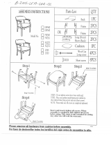
1 Frame, Weight Stack 1
2 Frame, Main 1
3 Crossbeam, Lower 1
4 Crossbeam, Upper 1
5 Handgrips 1
6 Post, Seat 1
7 Support, Back Cushion 1
8 Support, Seat Cushion 1
10 Actuator, Leverage Arm 1
11 Leverage Arm 1
13 Support, Lap Cushion 1
17 Cushion, Seat 1
19 Cushion, Leg 2
20 Belt 1
21 Retainer, Leg Cushion 1
22 Selector Pin 1
23 Shaft, Leverage Arm Actuator 1
26 Cushion, Back 1
27 Shaft, Leverage Arm 1
29 Washer, Aluminum 1
30 End Cap 4
34 Collar, Large 4
35 Collar 1
38 Shroud, Lower, Rear 1
39 Shroud, Lower, Front 1
40 Shroud, Upper 2
43 Retainer, Belt 2
46 Support, Weight Stack 2
47 Cap, Rubber 2
48 Guide Post, Weight Stack 2
49 Plate, Top, Weight Stack 1
50 Weight, 10lb 6
52 Nut, Tapped Hole 6
54 Washer, 25.5M 1
57 Setscrew 2
58 Setscrew 4
62 Screw 2
63 Screw, Flat Head Socket, 10X25M 9
65 Screw, Button Head Socket Cap, 8X20M 6
66 Screw, Button Head Socket Cap, 10X30M 4
67 Screw, Button Head Socket Cap, 10X35M 6
68 Screw, Button Head Socket Cap, 10X63M 2
69 Screw, Button Head Socket Cap, 10X80M 3
71 Screw, Button Head Socket Cap, 10X125M 2
72 Screw, Button Head Socket Cap, 10X130M 6
75 Lock Nut, Nylon Insert, 10M 15
77 Washer, 11M 6
78 Washer, 9M 38
79 Washer, Spring, 10M 3
80 Weight, 5lb 4
81 Weight, 15lb 4
■
Metric Hex Key Wrenches - 2.5mm, 5mm, 6mm, 8mm, 10mm
■
Metric Open-End Wrenches - 10mm, 15mm, 17mm
■
Metric Ratchet Socket Wrench Set (including 17mm socket)
■
Torque Wrench
■
Channel Lock Pliers
■
Vice Grip Pliers
■
Rubber Mallet
■
Phillips Head Screwdriver - #2