ASRock Rack EP2C621D16HM-AB User manual
- Category
- Server/workstation motherboards
- Type
- User manual
This manual is also suitable for

EP2C621D16HM-AB
EP2C622D16HM-C
User Manual
Version 1.0
Published April 2018
Copyright©2018 ASRock Rack INC. All rights reserved.

Version 1.0
Published July 2018
Copyright©2018 ASRock Rack Inc. All rights reserved.
Copyright Notice:
No part of this documentation may be reproduced, transcribed, transmitted, or
translated in any language, in any form or by any means, except duplication of
documentation by the purchaser for backup purpose, without written consent of
ASRock Rack Inc.
Products and corporate names appearing in this documentation may or may not
be registered trademarks or copyrights of their respective companies, and are used
only for identication or explanation and to the owners’ benet, without intent to
infringe.
Disclaimer:
Specications and information contained in this documentation are furnished
for informational use only and subject to change without notice, and should not
be constructed as a commitment by ASRock Rack. ASRock Rack assumes no
responsibility for any errors or omissions that may appear in this documentation.
With respect to the contents of this documentation, ASRock Rack does not provide
warranty of any kind, either expressed or implied, including but not limited to
the implied warranties or conditions of merchantability or tness for a particular
purpose.
In no event shall ASRock Rack, its directors, ocers, employees, or agents be liable
for any indirect, special, incidental, or consequential damages (including damages
for loss of prots, loss of business, loss of data, interruption of business and the
like), even if ASRock Rack has been advised of the possibility of such damages
arising from any defect or error in the documentation or product.
is device complies with Part 15 of the FCC Rules. Operation is subject to the following
two conditions:
(1) this device may not cause harmful interference, and
(2) this device must accept any interference received, including interference that
may cause undesired operation.
CALIFORNIA, USA ONLY
e Lithium battery adopted on this motherboard contains Perchlorate, a toxic substance
controlled in Perchlorate Best Management Practices (BMP) regulations passed by the
California Legislature. When you discard the Lithium battery in California, USA, please
follow the related regulations in advance.
“Perchlorate Material-special handling may apply, see www.dtsc.ca.gov/hazardouswaste/
perchlorate”
ASRock Rack’s Website: www.ASRockRack.com

Contact Information
If you need to contact ASRock Rack or want to know more about ASRock Rack,
you’re welcome to visit ASRock Rack’s website at www.ASRockRack.com; or you
may contact your dealer for further information.
ASRock Rack Incorporation
6F., No.37, Sec. 2, Jhongyang S. Rd., Beitou District,
Taipei City 112, Taiwan (R.O.C.)

Contents
Chapter 1 Introduction 1
1.1 Package Contents 1
1.2 Specications 2
1.3 Unique Features 5
1.4 Motherboard Layout 6
1.5 I/O Panel 9
1.6 Block Diagram 10
Chapter 2 Installation 12
2.1 Screw Holes 12
2.2 Pre-installation Precautions 12
2.3 Installing the CPU and Heatsink 13
2.4 Installation of Memory Modules (DIMM) 17
2.5 Expansion Slot (PCI Express Slot) 20
2.6 Jumper Setup 21
2.7 Onboard Headers and Connectors 23
2.8 Unit Identication purpose LED/Switch 29
2.9 Driver Installation Guide 29
2.10 M.2_SSD (NGFF) Module Installation Guide 30
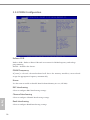
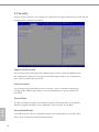
Chapter 3 UEFI Setup Utility 31
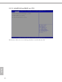
3.1 Introduction 31
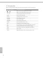
3.1.1 UEFI Menu Bar 31
3.1.2 Navigation Keys 32
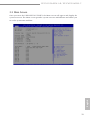
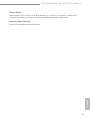
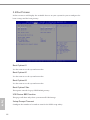
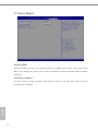
3.2 Main Screen 33

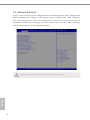
3.3 Advanced Screen 34
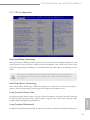
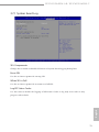
3.3.1 CPU Conguration 35
3.3.2 DRAM Conguration 38
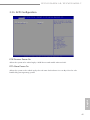
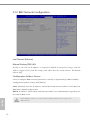
3.3.3 Chipset Conguration 40
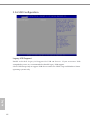
3.3.4 Storage Conguration 43
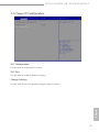
3.3.5 ACPI Conguration 45
3.3.6 USB Conguration 46
3.3.7 Super IO Conguration 47
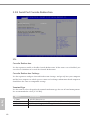
3.3.8 Serial Port Console Redirection 48
3.3.9 H/W Monitor 52
3.3.10 Runtime Error Logging 54
3.3.11 Intel SPS Conguration 56
3.3.12 Intel(R) VMD Technology 57
3.3.13 Intel(R) Virtual RAID on CPU 60
3.3.14 Instant Flash 61
3.4 Security 62
3.4.1 Key Management 63
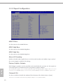
3.5 Boot Screen 66
3.5.1 CSM Parameters 68
3.6 Event Logs 70
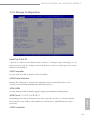
3.7 Server Mgmt 72
3.7.1 System Event Log 73
3.7.2 BMC Network Conguration 74
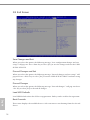
3.8 Exit Screen 76

Chapter 4 Software Support 77
4.1 Install Operating System 77
4.2 Support CD Information 77
4.2.1 Running The Support CD 77
4.2.2 Drivers Menu 77
4.2.3 Utilities Menu 77
4.2.4 Contact Information 77
Chapter 5 Troubleshooting 78
5.1 Troubleshooting Procedures 78
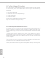
5.2 Technical Support Procedures 80
5.3 Returning Merchandise for Service 80
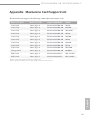
Appendix Mezzanine Card Support List 81

EP2C621D16HM-AB / EP2C622D16HM-C
PB 1
English
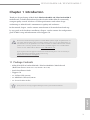
Chapter 1 Introduction
ank you for purchasing ASRock Rack EP2C621D16HM-AB / EP2C622D16HM-C
motherboard, a reliable motherboard produced under ASRock Rack’s consistently
stringent quality control. It delivers excellent performance with robust design
conforming to ASRock Rack’s commitment to quality and endurance.
In this manual, chapter 1 and 2 contains introduction of the motherboard and step-
by-step guide to the hardware installation. Chapter 3 and 4 contains the conguration
guide to BIOS setup and information of the Support CD.
1.1 Package Contents
• ASRock Rack EP2C621D16HM-AB / EP2C622D16HM-C Motherboard
(Half Form Factor: 20-in x 6.5-in, 50 cm x 16.5 cm)
• Quick Installation Guide
• Support CD
• 1 x SATA3 Cable (60 cm)
• 1 x MINISAS Cable(12G) 60cm
• 1 x Screw for M.2 Socket
If any items are missing or appear damaged, contact your authorized dealer.
Because the motherboard specications and the BIOS soware might be updated, the con-
tent of this manual will be subject to change without notice. In case any modications of
this manual occur, the updated version will be available on ASRock Rack website without
further notice. You may nd the latest memory and CPU support lists on ASRock Rack
website as well. ASRock Rack’s Website: www.ASRockRack.com
If you require technical support related to this motherboard, please visit our website for
specic information about the model you are using.
http://www.asrockrack.com/support/

2 3
English
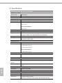
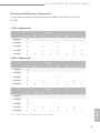
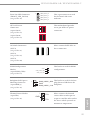
1.2 Specications
EP2C621D16HM-AB / EP2C622D16HM-C
MB Physical Status
Form Factor Half Width
Dimension 20’’ x 6.5’’ (50cm x 16.5 cm)
Processor System
CPU Intel® Xeon® Scalable Processor
Socket Dual Socket P, LGA3647
Chipset EP2C621D16HM-AB:
Intel®C621
EP2C622D16HM-C:
Intel®C622
System Memory
Capacity 16 DIMM slots
Type - Six Channels memory technology
- Support DDR4 2666/2400 RDIMM and LRDIMM
Volt age 1.2V
DIMM Sizes RDIMM: 32GB, 16GB, 8GB, 4GB
LRDIMM: 64GB, 32GB
Expansion Slot
PCIe 3.0 x 16 2 slots
Mezzanine slot EP2C621D16HM-AB:
1 x Mezzanine Type A
1 x Mezzanine Type B
EP2C622D16HM-C:
1 x Mezzanine Type C
Storage
SATA Controller 10 x SATA3 (including 1x SATA DOM ports and 1x M.2 ports)
Management
BMC Controller ASPEED AST2500
IPMI Dedicated
GLAN
1 x Realtek RTL8211E for dedicated management GLAN
Features - Watch Dog
- NMI
Graphics
Controller ASPEED AST2500
VRAM DDR4 16MB
Rear Panel I/O
VGA Port 1 x D-Sub
USB 3.0 Port 2
LAN Port 1 (IPMI) Lan port (RJ45)
LAN Ports with LED (ACT/LINK LED and SPEED LED)

EP2C621D16HM-AB / EP2C622D16HM-C
2 3
English
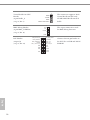
Internal Connector
Auxiliary Panel
Header
1 (includes chassis intrusion, location button & LED, front
LAN LED)
TPM Header 1
IPMB Header 1
Fan Header 4x system Fan (6-pin)
USB 2.0 Header 1 ( supports 2 USB 2.0)
M.2 1 (up to 2280)
SATA DOM 1
Mezzanine EP2C621D16HM-AB:
1 x Mezzanine Type A
1 x Mezzanine Type B
EP2C622D16HM-C:
1 x Mezzanine Type C
System BIOS
BIOS Ty pe 256Mb AMI UEFI Legal BIOS
BIOS Features - Plug and Play (PnP)
- ACPI 2.0 Compliance Wake Up Events
- SMBIOS 2.8 Support
- ASRock Rack Instant Flash
Hardware Monitor
Temperature - CPU Temperature Sensing
- System Temperature Sensing
Fan - CPU/Rear/Front Fan Tachometer
- CPU Quiet Fan (Allow Chassis Fan Speed Auto-Adjust by
CPU Temperature)
- CPU/Rear/Front Fan Multi-Speed Control
Volt age Voltage Monitoring: +12V, +5V, +3.3V, CPU Vcore, DRAM,
1.05V_PCH, +BAT, 3VSB, 5VSB
Support OS
OS Microso® Windows® (Server OS)
- Server 2012 R2 (64 bit)
- Server 2016 (64 bit)
Linux®
- RedHat Enterprise Linux Server 6.8 (64 bit) / 7.2 (64 bit)
- CentOS 6.8 (64 bit) / 7. 2 (64 bit)
- SUSE Enterprise Linux Server 11 SP4 (64 bit) /12 SP3 (64 bit)
- FreeBSD 11 (64 bit)
- Ubuntu 16.04/15.10 (64 bit)
Virtual:
- VMWare ESXi 6.5

4 5
English
is motherboard supports Wake from on Board LAN. To use this function, please make
sure that the “Wake on Magic Packet from power o state” is enabled in Device Manager
> Intel® Ethernet Connection > Power Management. And the “PCI Devices Power On” is
enabled in UEFI SETUP UTILITY > Advanced > ACPI Conguration. Aer that, onboard
LAN1&2 can wake up S5 under OS.
If you install Intel® LAN utility or Marvell SATA utility, this motherboard may fail Win-
dows® Hardware Quality Lab (WHQL) certication tests. If you install the drivers only, it
will pass the WHQL tests.
* Please refer to our website for the latest OS support list.
* Before installing the Linux OS, please rst enter the BIOS settings, go to
“Advanced” > “Chipset Conguration” and set “IGPU Multi-Monitor” option
to “Disabled”.
Environment
Temperature Operation temperature: 10°C ~ 35°C / Non operation
temperature: -40°C ~ 70°C

EP2C621D16HM-AB / EP2C622D16HM-C
4 5
English
1.3 Unique Features
ASRock Rack Instant Flash is a BIOS ash utility embedded in Flash ROM. is con-
venient BIOS update tool allows you to update system BIOS without entering operat-
ing systems rst like MS-DOS or Windows®. With this utility, you can press the <F6>
key during the POST or the <F2> key to enter into the BIOS setup menu to access
ASRock Rack Instant Flash. Just launch this tool and save the new BIOS le to your
USB ash drive, oppy disk or hard drive, then you can update your BIOS only in a
few clicks without preparing an additional oppy diskette or other complicated ash
utility. Please be noted that the USB ash drive or hard drive must use FAT32/16/12
le system.

6 7
English
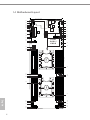
1.4 Motherboard Layout
16.5cm (6.5 in)
50cm (20 in)
VGA1
1
IPMI_
LAN1
TPM1
1
PSU_SMB1
1
IPMB1
HDLED RESET
PLED PWRBTN
PANEL1
1
UID
1
AUX_PANEL1
11
1
1
SATA_0
11
PCIE1
BIOS
ROM
NMI_BTN1
FRON_LED_LAN34
USB 3.0
T: USB2
B: USB1
11
11
T 1
RSATAPWR1
BMC_SMB2
1
HSBP_1
MEZZ_MB_A1
11
11
DDR4_L1(64 bit, 288-pin module, Blue)
DDR4_K1 (64 bit, 288-pin module, Blue)
DDR4_J1 (64 bit, 288-pin module, Blue)
DDR4_J2 (64 bit, 288-pin module, White)
DDR4_G2(64 bit, 288-pin module, White)
DDR4_G1(64 bit, 288-pin module, Blue)
DDR4_H1 (64 bit, 288-pin module, Blue)
DDR4_I1(64 bit, 288-pin module, Blue)
DDR4_F1(64 bit, 288-pin module, Blue)
DDR4_E1Blue(64 bit, 288-pin module,)
DDR4_D1 (64 bit, 288-pin module, Blue)
DDR4_D2 (64 bit, 288-pin module, White)
DDR4_A2 (64 bit, 288-pin module, White)
DDR4_A1 (64 bit, 288-pin module, Blue)
DDR4_B1 Blue(64 bit, 288-pin module,)
DDR4_C1 (64 bit, 288-pin module, Blue)
25
29
30
14
15
16
17
18
19
27
CPU1
31
USB_5_6
1
PCIE2
1
CHASSIS_ID1
1
CHASSIS_ID0
NUT80
M2_1
NUT80
M2_1
BMC
ROM
MEZZ_MB_B1
MEZZ_1_C1
Intel
C621/
C622
11
OCU3
OCU1
OCU2
SYSTEM_FAN1
SYSTEM_FAN2
SYSTEM_FAN4
SYSTEM_FAN3
1
J4
CON28
CON27
BAT1
SATA_0_7
PECI1
(EP2C622D16HM)
(EP2C621D16HM-AB)
(EP2C621D16HM-AB)
CPU2
BMC
AST2500
Super
I/O
RAID_1
1
BMC_DEBUG1ME_RECOVERY1 PWM_CFG
26
24
23
32
33
34
35
36
37
38
39
40
7
13
1
2
3
4
5
6
12
9
10
11
20
21
22
28
41
42
43
44
45
46
47
8

EP2C621D16HM-AB / EP2C622D16HM-C
6 7
English
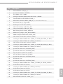
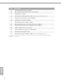
No. Description
1 USB 2.0 Header (USB_5_6)
2 System Panel Header (PANEL1)
3PSU SMBus (PSU_SMB1)
4 Intelligent Platform Management Bus header (IPMB1)
5 Virtual RAID On CPUHeader (RAID_1)
6 Mezzanine Card Slot (MEZZ_MB_B1) (for EP2C621D16HM-AB only)
7 M.2 Socket (M2_1) (Type 2280)
8 PCI Express 3.0 x16 Slot (PCIE2)
9 Chassis ID1 Jumper (CHASSIS_ID1)
10 Chassis ID0 Jumper (CHASSIS_ID0)
11 BMC Debug Header (BMC_DEBUG1)
12 ME Recovery Jumper (ME_RECOVERY1)
13 PWM Conguration Header (PWM_CFG)
14 CPU Socket 1 LGA-3647 (Socket P) (CPU1)
15 3 x 288-pin DDR4 DIMM Slots (DDR4_A1, DDR4_B1, DDR4_C1, Blue)*
16 1 x 288-pin DDR4 DIMM Slot (DDR4_A2, White)*
17 CPU Socket 2 LGA-3647 (Socket P) (CPU2)
18 3 x 288-pin DDR4 DIMM Slots (DDR4_G1, DDR4_H1, DDR4_I1, Blue)*
19 1 x 288-pin DDR4 DIMM Slot (DDR4_G2, White)*
20 System Fan Connector (SYSTEM_FAN1)
21 System Fan Connector (SYSTEM_FAN2)
22 ATX 12V Power Connector (CON27)
23 ATX 12V Power Connector (CON28)
24 System Fan Connector (SYSTEM_FAN4)
25 PSU Header (J4)
26 System Fan Connector (SYSTEM_FAN3)
27 3 x 288-pin DDR4 DIMM Slots (DDR4_J1, DDR4_K1, DDR4_L1, Blue)*
28 OCuLink x4 Connector (OCU2)
29 1 x 288-pin DDR4 DIMM Slot (DDR4_J2, White)*
30 OCuLink x4 Connector (OCU3)
31 OCuLink x4 Connector (OCU1)
32 3 x 288-pin DDR4 DIMM Slots (DDR4_D1, DDR4_E1, DDR4_F1, Blue)*
33 1 x 288-pin DDR4 DIMM Slot (DDR4_D2, White)*
34 Mini SAS HD Connector (SATA_0_7)

8 9
English
No. Description
35 CPU PECI Mode Jumper (PECI1)
36 Non Maskable Interrupt Button (NMI_BTN1)
37 TPM Header (TPM1)
38 Mezzanine Card Slot (MEZZ_MB_A1) (for EP2C621D16HM-AB only)
39 Auxiliary Panel Header (AUX_PANEL1)
40 PCI Express 3.0 x8 Slot (PCIE1)
41 BMC SMBus Header (BMC_SMB_1)
42 Backplane PCI Express Hot-Plug Connector (HSBP_1)
43 Front LAN LED Connector (FRONT_LED_LAN34)
44 SATA DOM Connector (SATA_0)
45 SATA DOM Power Jumper (SATAPWR1)
46 ermal Sensor Header (TR1)
47 Mezzanine Card Slot (MEZZ_MB_C1) (for EP2C622D16HM-C only)
*For DIMM installation and conguration instructions, please see p.19 (Installation of Memory Modules
(DIMM)) for more details.

EP2C621D16HM-AB / EP2C622D16HM-C
8 9
English
4
3
21
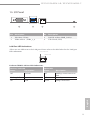
1.5 I/O Panel
No. Description No. Description
1VGA Port (VGA1) 3 LAN RJ-45 Port (IPMI_LAN1)*
2 USB 3.0 Ports (USB3_1_2) 4 UID Switch (UID)
LAN Port LED Indications
*ere are two LED next to the LAN port. Please refer to the table below for the LAN port
LED indications.
Dedicated IPMI LAN Port LED Indications
Activity / Link LED Speed LED
Status Description Status Description
O No Link O 10M bps connection or no
link
Blinking Yellow Data Activity Yel low 100M bps connection
On Link Green 1Gbps connection
ACT/LINK LED
SPEED LED
LAN Port

10 11
English
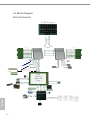
1.6 Block Diagram
EP2C621D16HM-AB
LPC
UPI0
UPI1
Channel A
Channel B
Channel C
Channel D
Channel E
Channel F
Channel G
Channel H
Channel I
Channel J
Channel K
Channel L
DMI 3.0 x4
x16 PCIe Gen3
3
PCH
LBG-1G
(TDP 15W)
C621
x16 PCIe Riser
x4 PCIe Gen 3
10x SATA3
M.2
SATA DOM
2x USB 3.0 Rear I/O
x1 PCIe Gen2
BMC IPMI/Dedicate Port
TPM HEADER
DDR4
2x USB 2.0 Internal
SMBus
IPMB HEADER
4x system Fan
UID
x4 PCIe Gen3
x4 PCIe Gen 3
PWR 12V IN
2U4N-F
OCP 2.0 Conn. A
OCP 2.0 Conn. B
x16 PCIe Gen3
X16 PCIe BOM optional
for OCP 2.0 CONN.A and B
x16 PCIe Gen3
x16 PCIe Riser
2U4N-F Seriers
AEP for channel A/D AEP for channel G/J
Intel® Xeon®
Scalable Processor Intel® Xeon®
Scalable Processor

EP2C621D16HM-AB / EP2C622D16HM-C
10 11
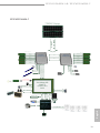
English
LPC
UPI0
UPI1
Channel A
Channel B
Channel C
Channel D
Channel E
Channel F
Channel G
Channel H
Channel I
Channel J
Channel K
Channel L
DMI 3.0 x4
x16 PCIe Gen3
3
Lewisbrug-NS
LBG-2
(TDP 17W)
C622
x16 PCIe Riser
10x SATA3
M.2
SATA DOM
2x USB 3.0 Rear I/O
x1 PCIe Gen2
TPM HEADER
DDR4
2x USB 2.0 Internal
SMBus
IPMB HEADER
4x system Fan
UID
x4 PCIe Gen3
x4 PCIe Gen 3
PWR 12V IN
2U4N-F
OCP 2.0 Conn. C
x4 KR BOM optional
for OCP 2.0 CONN.C
x16 PCIe Gen3
x16 PCIe Gen3
x16 PCIe Riser
2U4N-F Seriers
AEP for channel A/D AEP for channel G/J
Intel® Xeon®
Scalable Processor Intel® Xeon®
Scalable Processor
x4 PCIe Gen 3
BMC IPMI/Dedicate Port
EP2C622D16HM-C

12 13
English
Chapter 2 Installation
is is a half form factor (20’’ x 6.5’’, 50 cm x 16.5 cm) motherboard. Before you install the
motherboard, study the conguration of your chassis to ensure that the motherboard ts
into it.
EP2C621/EP2C622 Series are dual socket motherboards that support Intel® Xeon® Scalable
Processor. Please install a primary processor (BootStrap Processor) into “CPU1” socket
and then install a non-Primary Processor (Application Processors) into “CPU2” socket.
*For a single CPU, please install it into “CPU1” socket (framed by a square).
Make sure to unplug the power cord before installing or removing the motherboard. Failure
to do so may cause physical injuries to you and damages to motherboard components.
2.1 Screw Holes
Place screws into the holes indicated by circles to secure the motherboard to the chassis.
Do not over-tighten the screws! Doing so may damage the motherboard.
2.2 Pre-installation Precautions
Take note of the following precautions before you install motherboard components or
change any motherboard settings.
1. Unplug the power cord from the wall socket before touching any components.
2. To avoid damaging the motherboard’s components due to static electricity, NEVER
place your motherboard directly on the carpet or the like. Also remember to use a
grounded wrist strap or touch a safety grounded object before you handle the compo-
nents.
3. Hold components by the edges and do not touch the ICs.
4. Whenever you uninstall any component, place it on a grounded anti-static pad or in
the bag that comes with the component.
5. When placing screws into the screw holes to secure the motherboard to the chassis,
please do not over-tighten the screws! Doing so may damage the motherboard.
Before you install or remove any component, ensure that the power is switched o or the
power cord is detached from the power supply. Failure to do so may cause severe damage to
the motherboard, peripherals, and/or components.

EP2C621D16HM-AB / EP2C622D16HM-C
12 13
English
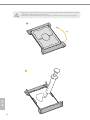
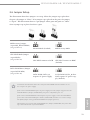
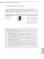
2.3 Installing the CPU and Heatsink
1. Before you insert the CPU into the socket, please check if the PnP cap is on the socket,
if the CPU surface is unclean, or if there are any bent pins in the socket. Do not force to
insert the CPU into the socket if above situation is found. Otherwise, the CPU will be
seriously damaged.
2. Unplug all power cables before installing the CPU.
1
2

14 15
English
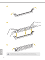
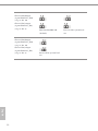
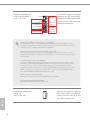
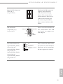
1. Before you installed the heatsink, you need to spray thermal interface material between the CPU
and the heatsink to improve heat dissipation.
2. Illustration in this documentation are examples only. Heatsink or fan cooler type may dier.
3
4
180o
Page is loading ...
Page is loading ...
Page is loading ...
Page is loading ...
Page is loading ...
Page is loading ...
Page is loading ...
Page is loading ...
Page is loading ...
Page is loading ...
Page is loading ...
Page is loading ...
Page is loading ...
Page is loading ...
Page is loading ...
Page is loading ...
Page is loading ...
Page is loading ...
Page is loading ...
Page is loading ...
Page is loading ...
Page is loading ...
Page is loading ...
Page is loading ...
Page is loading ...
Page is loading ...
Page is loading ...
Page is loading ...
Page is loading ...
Page is loading ...
Page is loading ...
Page is loading ...
Page is loading ...
Page is loading ...
Page is loading ...
Page is loading ...
Page is loading ...
Page is loading ...
Page is loading ...
Page is loading ...
Page is loading ...
Page is loading ...
Page is loading ...
Page is loading ...
Page is loading ...
Page is loading ...
Page is loading ...
Page is loading ...
Page is loading ...
Page is loading ...
Page is loading ...
Page is loading ...
Page is loading ...
Page is loading ...
Page is loading ...
Page is loading ...
Page is loading ...
Page is loading ...
Page is loading ...
Page is loading ...
Page is loading ...
Page is loading ...
Page is loading ...
Page is loading ...
Page is loading ...
Page is loading ...
Page is loading ...
-
 1
1
-
 2
2
-
 3
3
-
 4
4
-
 5
5
-
 6
6
-
 7
7
-
 8
8
-
 9
9
-
 10
10
-
 11
11
-
 12
12
-
 13
13
-
 14
14
-
 15
15
-
 16
16
-
 17
17
-
 18
18
-
 19
19
-
 20
20
-
 21
21
-
 22
22
-
 23
23
-
 24
24
-
 25
25
-
 26
26
-
 27
27
-
 28
28
-
 29
29
-
 30
30
-
 31
31
-
 32
32
-
 33
33
-
 34
34
-
 35
35
-
 36
36
-
 37
37
-
 38
38
-
 39
39
-
 40
40
-
 41
41
-
 42
42
-
 43
43
-
 44
44
-
 45
45
-
 46
46
-
 47
47
-
 48
48
-
 49
49
-
 50
50
-
 51
51
-
 52
52
-
 53
53
-
 54
54
-
 55
55
-
 56
56
-
 57
57
-
 58
58
-
 59
59
-
 60
60
-
 61
61
-
 62
62
-
 63
63
-
 64
64
-
 65
65
-
 66
66
-
 67
67
-
 68
68
-
 69
69
-
 70
70
-
 71
71
-
 72
72
-
 73
73
-
 74
74
-
 75
75
-
 76
76
-
 77
77
-
 78
78
-
 79
79
-
 80
80
-
 81
81
-
 82
82
-
 83
83
-
 84
84
-
 85
85
-
 86
86
-
 87
87


ASRock Rack EP2C621D16HM-AB User manual
- Category
- Server/workstation motherboards
- Type
- User manual
- This manual is also suitable for
Ask a question and I''ll find the answer in the document
Finding information in a document is now easier with AI