Page is loading ...

Rail-Split RDM
Category
G) DMX Splitters
Description
6 port DMX512 splitter, housed in a DIN Rail Enclosure, with support
for RDM and HES Talkback.
Mechanical Control
• Control: 6 Port DMX / RDM Splitter
• Input Protocols:
• Housing: DIN Rail Case
• Material: Lexan Plastic - UL94-V0 rated
• DMX512, DMX512(1990), DMX512-A
• Overall Dimensions: 88mm (W) x 90mm (H) x 58mm (D)
• RDM V1.0 (E1.20 - 2006 ESTA Standard)
• High End Systems Talkback
• Input Connector: Screw Terminal (2.5mm² max wire size)
• Mass: 0.25kg
• Mounting: 35mm DIN Rail or Surface Mount
• Country of Manufacture: United Kingdom
• Output Protocols: Same as input
• Output Connector: Screw Terminal (2.5mm² max wire size)
Isolation / Protection Electrical
• Isolation:
• DMX Input Opto-Isolated to 1kV
• DMX Output - Ground Referenced
• Input Voltage: 9V-48VDC
• Input Connector: Screw Terminal (2.5mm² max wire size)
• Input Power (max): 8W
• Duty Cycle: 80% @ 25°C
• Protection:
• Internal Resettable Fuse - Control Electronics
• +15kV ESD DMX Driver Protection
Environmental Package Contents
• Rail-Split RDM
• Operating Temperature: 0°C to 40°C
• User Guide
• Storage Temperature: -10°C to +50°C
• Operating Relative Humidity (max): 80% Non-Condensing
• IP Rating: IP20 Indoor Use Only
• Certification: CE FCC, WEEE, RoHS
• Warranty: 2 Year (Return to Base)
User Interface / Indication Ordering Info
Product Code: Rail-Split RDM
• Connections:
Accessories (not included):
• (1) 3pin Screw Terminal DMX Input
PSU-9-1.5-FER
• (1) 3pin Screw Terminal DMX Loop
• (1) 2pin Screw Terminal DC Voltage Input
• (6) 3pin Screw Terminal DMX Output
• Indication: Power / DMX / RDM
A
rtistic Licenc
e
Rail-Split RDM

Mounting Drawing
A
rtistic Licenc
e
Rail-Split RDM
Wiring Drawing

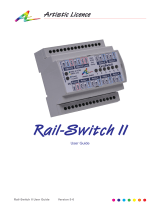
Rail-Split RDM User Guide
(Version 2.3)
Rail-Split RDM is a fully bi-directional DMX512 splitter and distribution
amplifier.
Key Features include:
Input Optical Isolation
Six independent outputs
Bi-directional outputs
RDM (Remote Device Management Draft & Standard V1.0)
DMX512-A compatible
Microprocessor controlled
Surface mount or DIN rail mounted
Support for High End System talkback protocol
Specification:
Input Voltage: 9-48V DC
Maximum Current: 1.5 A
Internal Fuse: Electronic Resettable Fuse
Duty Cycle: 80%
Dimensions: W:88 H:90 D:58mm
Mounting: DIN Rail or surface mount
IP: Indoor use only
Listings: CE, FCC
Max Wire Size: 2.5mm2
Power Supply Options: (order separately)
PSU-9-1.5-FER
Output: 9V 1.5A
Input: Auto-sensing
Max Rail-Splits: 1.5
Listing: CE / FCC / UL / PSE
PSU-24-2-FER
Output: 24V 2A
Input: Auto-sensing
Max Rail-Splits: 2
Listing: CE / FCC / UL / PSE
Copyright © Artistic Licence Engineering Ltd. All rights reserved.

Rail-Split RDM Wiring Diagram:
Note: It is recommended that wires from the PSU to the Rail-Split RDM have a ferrite core, or similar suppression
device, fitted. This should be located close to the Rail-Split RDM.
DMX512 Wiring:
DIN Rail Surface Mounting:
To use the surface mount
option push the three bottom
tabs out until they click into
place. We recommend using an
M4 Pan head screw.
XLR Pin
(Convention)
Rail-Split RDM
Terminals
Function Colour
1 GND Ground Black
2 DAT- Data - Blue
3 DAT+ Data + Red
4 No Connection
5 No Connection
98.00 mm
90.00 mm
44.00 mm
88.00 mm
22.70 mm
65.30 mm
22.70 mm

Input:
The DMX512 input is attached via three screw terminals. Please refer to the
wiring diagram.
Loop Through:
A passive Loop Through connection allows onward connection to other
DMX512 devices. If this feature is not required a wire link must be fitted to
the correct screw terminals that will terminate the DMX line. Please refer to
the wiring diagram.
Output:
Six DMX512 outputs are provided. Each output is capable of driving 32
additional DMX512 devices. It is not necessary to terminate any outputs that
are not connected. However, a terminator must be connected to the final
DMX512 device.
Indicators:
Two dual colour indicators are provided:
1. Data:
Green: Indicates that DMX512 is being transmitted by the outputs.
Red: Indicates that RDM data received by one of the outputs is being
returned to the controller.
2. Power:
Red: Indicates good power and normal operation.
Flashing: Indicates that a connected RDM device is jabbering
(returning unwanted data continuously).
System Connection:
The following table summarises the internal earth interconnection and isolation:
Please note that we use the term Earth-Ground to avoid international confusion. In
Europe Earth-Ground is called Earth, in the USA Earth-Ground is called Ground.
Circuit Description
Type: Isolated. DMX512 Input
(including Loop
Through)
Pin 1: Connects to internal isolated
circuit. No connection to
Internal Logic Ground.
Type: Grounded. DMX512 Outputs
Pin 1: Connected to Internal Logic
Ground.
Internal Logic
Ground
Connects to Ground Power Input
CE Compliance
Rail-Split RDM is CE compliant when installed in a shielded and earthed metal case

The DIN Rail Range:
Rail-Split RDM – A fully bi-directional six channel DMX512 splitter and
distribution amplifier
Rail-Pipe – A six channel intelligent power supply / low voltage
dimmer
Rail-Switch – Provides six mains voltage relays with DMX512 and RDM
Draft V1.0 support
Rail-Demux – Provides 16 DMX512 to analogue outputs and RDM Draft
V1.0 support
Rail-Tran – Provides six Darlington transistor outputs, operation to
50V DC at 450mA, product total 750mA
Rail-DALI – A 256 channel bi-directional DMX / DALI interface
Rail-Patch – A DIN Rail mounted patch panel for a 5pin XLR to screw
terminal connection
Rail-PSU-D4 – A four circuit DALI Bus PSU
CP12 – An LED dimmer designed to control high power LED devices
Net-Pipe – A high power Ethernet controlled LED dimmer
The information contained in this document is subject to change without notice. Artistic Licence Engineering Ltd.
makes no warranty of any kind with regard to this material, including, but not limited to, the implied warranties
of fitness for a particular purpose.
Artistic Licence Engineering Ltd. shall not be liable for errors contained herein or for incidental or consequential
damages in connection with the furnishing, performance or use of this material. All trademarks are acknowledged.
A
rtistic Licenc
e
© Artistic Licence Engineering Ltd. 2004
24 Forward Drive
Christchurch Avenue
Harrow
Middlesex
England
HA3 8NT
Tel: +44 (0)20 88 63 45 15
Fax: +44 (0)20 84 26 05 51
Email: Sales@ArtisticLicence.com
/