
KN MR-78
Metal rack
78
”
Estante metálico
(1,981.2 mm)
We encourage you to read the user manual
before using your equipment.
Lo invitamos a leer el instructivo del usuario
antes de usar su equipo.

METAL RACK KN MR-78
Rubber mallet, gloves and wrench
Description Quantity
A: Frame 2
B: Beam 8
C: Cross bar-A 12
D: Cross bar-B 4
E: Wire deck 4
F: Bolt nut washer 8 set
CONTENTS
COMPONENTS
A: Frame
B: Beam
C: Cross bar-A
E: Wire deck
F: Bolt nut washer
D: Cross bar-B
GENERAL INSTRUCTIONS
Assembly of this unit is done by tting the brackets of the
beams into the slots of the post frames.
A rubber mallet should be used on the ledge of the beams
to properly seat the beam brackets. If a hammer is used
care should be taken to protect the beam surface to avoid
damage by using a protective cloth or block of wood.
The stepped surface of the beam ledge is the top, and
should face upwards. This is the surface that the wire deck
will rest on.
A bracket should engage and t rmly into the tapered slot
of the post frame. This engagement is a tight swaged t
and will apply resistance as it fully engages. A visual
inspection should be made to show that the bracket is
properly engaged in the slot.
After assembly re-check each beam for proper engagement.
SAFETY INSTRUCTIONS
This unit should be placed on a level surface. Failure to do so
can result in poor product performance or create a possible
safety hazard.
This unit should be securely anchored to a wall or oor with
suitable fasteners, which are not included.
Do not use this unit for anything
other than the manufacture’s
intended purpose.
DO NOT STAND ON ANY
PART OF THE UNIT, OR
USE IT AS A LADDER.
Use care when working
with metal parts. Wear
gloves for protection.
Evenly distribute the weight
on each level and always keep
the heavier loads on the bottom.
• Attach the beams to the welded end frame posts
(see gure 1) starting at the bottom level by using both end
frames to establish the left and the right sides of the units.
• After a beam has been placed in both end frame post slots,
tap the beam down at both ends with a rubber mallet to
help drive the beam bracket tabs into the slots to secure
the beam. Continue assembling each level from bottom to
top level (front and back).
• If the beam bracket tabs become bent due to mishandling,
it may be necessary to adjust the tabs back to their proper
form.
ASSEMBLY INSTRUCTIONS
End frame post
End frame
post slots
Beam
bracket tabs
Beam
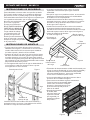
Install cross bar B in each level by inserting and tightening
the bolt, nut, washer into the holes located along the inside
both
Figure 1
• The completed unit should have four (4) levels evenly
spaced for maximum stability.
• Although the beams are adjustable in height, it’s
recommended to evenly space them so that the stability
of the unit is not compromised.
• Install cross bar B in each level by inserting and tightening
the bolts, nuts, washers into the holes located along the
inside bottom center edge of the beams(see gure 2)
ITEMS YOU MIGHT FIND HELPFUL

A: Cuadro
B: Viga
C: Barra
transversal-A
E: Cubierta de
alambre
F: Arandela de
tuerca de tornillo
D: Barra transversal-B
METAL RACK KN MR-78
• Install cross bar A in each level by inserting the tab located
on both ends of the cross bar A into the slot holes located
along the inside top edge of the beams(see gure 2)
• Insert wire deck on
each level (gure 3).
• Assembly is
now complete
Inside top
edge of beam
Cross bar-A
Cross bar-B
Inside bottom
center edge
of beam
Bolt nut
washer
Figure 2 Figure 3
Wire deck
• Welded Storage Rack is engineered to offer
maximum exibility as well as ease and
quickness of assembly. The rack units
can stand individually, or for greater
stability, be joined together
using the common post.
• Individual beams can
be adjusted without
disturbing the beams
in adjoining units.
• These instructions
should be followed
exactly. All parts
supplied must be used
as shown. Any
alteration or deviation
from this instruction
sheet can result in
unit failure.
• After the unit is assembled,
it must be placed on a level
surface for safety, and
optimal product performance.
ESTANTE METÁLICO KN MR-78
Mazo de goma, guantes y llave
Descripción Cantidad
A: Cuadro 2
B: Viga 8
C: Barra transversal-A 12
D: Barra transversal-B 4
E: Cubierta de alambre 4
F: Arandela de tuerca de tornillo 8 juegos
CONTENIDO
COMPONENTES
ELEMENTOS QUE PUEDEN RESULTARLE ÚTILES
INSTRUCCIONES GENERALES
El ensamblaje de esta unidad se realiza encajando los soportes
de las vigas en las ranuras de los marcos de los postes.
Se debe usar un mazo de goma en el borde de las vigas para
asentar correctamente los soportes de las vigas. Si se utiliza
un martillo, se debe tener cuidado de proteger la supercie de
la viga para evitar daños mediante el uso de un paño
protector o un bloque de madera.
La supercie escalonada del borde de la viga es la parte
superior y debe mirar hacia arriba. Esta es la supercie sobre
la que descansará la plataforma de alambre.
Un soporte debe encajar y encajar rmemente en la ranura
cónica del marco del poste. Este enganche es un ajuste
estampado apretado y aplicará resistencia a medida que
enganche por completo. Se debe realizar una inspección
visual para mostrar que el soporte está correctamente
acoplado en la ranura.
Después del montaje, vuelva a comprobar cada viga para ver
si encaja correctamente.

ESTANTE METÁLICO KN MR-78
INSTRUCCIONES DE SEGURIDAD
Esta unidad debe colocarse sobre una supercie nivelada.
El no hacerlo puede resultar en un rendimiento deciente
del producto o crear un posible peligro para la seguridad.
Esta unidad debe anclarse de forma segura a una pared o piso
con sujetadores adecuados, que no están incluidos.
No utilice esta unidad para nada
que no sea el propósito
previsto por el fabricante.
NO SE PARE EN NINGUNA
PARTE DE LA UNIDAD NI
LA USE COMO ESCALERA.
Tenga cuidado al trabajar
con piezas de metal. Use
guantes para protección.
Distribuya uniformemente el
peso en cada nivel y mantenga
siempre las cargas más pesadas
en la parte inferior.
• Fije las vigas a los postes del marco de los extremos
soldados (vea la gura 1) comenzando en el nivel inferior
usando ambos marcos de los extremos para establecer
los lados izquierdo y derecho de las unidades.
• Después de colocar una viga en las ranuras de los postes
del marco de ambos extremos, golpee la viga hacia abajo
en ambos extremos con un mazo de goma para ayudar a
introducir las lengüetas del soporte de la viga en las ranuras
para asegurar la viga. Continúe ensamblando cada nivel de
abajo hacia arriba (frente y atrás).
• Si las lengüetas del soporte de la viga se doblan debido a
un mal manejo, puede ser necesario volver a ajustar
las lengüetas a su forma correcta.
INSTRUCCIONES DE MONTAJE
Poste de marco nal
Ranuras para postes
del marco nal
Pestañas de
soporte de viga
Viga
Figura 1
Instale la barra transversal B en cada nivel insertando y
apretando el perno, la tuerca y la arandela en los oricios
ubicados a lo largo del interior de ambos
• La unidad completa debe tener cuatro (4) niveles
espaciados uniformemente para lograr la máxima
estabilidad.
• Aunque las vigas son ajustables en altura, se recomienda
espaciarlas uniformemente para que la estabilidad de
la unidad no se vea comprometida.
• Instale la barra transversal B en cada nivel insertando y
apretando los pernos, tuercas y arandelas en los oricios
ubicados a lo largo del borde central inferior interior
de las vigas (vea la gura 2)
• Instale la barra transversal A en cada nivel insertando
la lengüeta ubicada en ambos extremos de la barra
transversal A en los oricios ranurados ubicados a lo largo
del borde superior interior de las vigas (vea la gura 2)
• Inserte la plataforma de alambre
en cada nivel (gura 3).
• El montaje ya
está completo
Borde superior
interior de la viga
Barra
transversal-A
Barra
transversal-B
Borde central
inferior interior
de la viga
Arandela de tuer-
ca de tornillo
Figura 2
Figura 3
Cubierta
de alambre
• El bastidor de almacenamiento soldado está diseñado para
ofrecer la máxima exibilidad, así como también facilidad y
rapidez de montaje. Las unidades de estante pueden
colocarse individualmente o, para mayor estabilidad,
unirse entre sí mediante el poste común.
• Los haces individuales se pueden ajustar sin alterar
los haces de las unidades contiguas.
• Estas instrucciones deben seguirse exactamente.
Todas las piezas suministradas deben
usarse como se muestra. Cualquier
alteración o desviación de esta hoja
de instrucciones puede provocar
fallas en la unidad.
• Después de ensamblar
la unidad, debe
colocarse sobre una
supercie nivelada
por seguridad y un
rendimiento óptimo
del producto.
-
 1
1
-
 2
2
-
 3
3
-
 4
4


Ask a question and I''ll find the answer in the document
Finding information in a document is now easier with AI
in other languages
Other documents
-
 Storage Works 8529620 Owner's manual
-
DeWalt DXST6000WB User manual
-
-
-
-
One Stop Gardens Item 63354 Owner's manual
-
Harbor Freight Tools 6 ft. x 8 ft. Greenhouse Owner's manual
-
Swing-N-Slide Playsets PB 9240-013 Operating instructions
-
Husky MR602478W5BH User manual
-
