Page is loading ...

451-0312M MRV Communications, Inc. www.mrv.com 1
LX-4000 Quick Start Instructions
451-0312M
This document is intended to help you get your LX-4000 unit up and running quickly. It includes
basic hardware installation, POST test information, how to obtain IP information, and how to
perform a first time quick software installation. If you prefer a more detailed explanation of these
procedures, refer to the Getting Started with the LX-4000 Series manual.
Rack-Mounting the Unit
• Do not choose a location where the unit will be exposed to direct sunlight or subjected to vibration.
• Unit must be installed in an environment with 5% to 90% humidity, noncondensing, 0° - 40° C
(32°-104° F).
• Do not place an object on the side(s) of the unit that might block airflow through the unit.
• The unit may be front, rear, or center mounted.
• There is no mounting difference between the 19” and 23” rack mount ears.
• MRV provides the following mounting screws: Eight 6-32 x 5/16” flathead screws for attaching the
ears to the unit, and four 10-32 screws to attach to the rack.
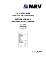
Figure 1 - Mounting an LX-4000 Series in Rack
The three bottom side screws hold
the cover on the unit. To front-mount
the unit, you must
attaching the rack-mount brackets.
Then insert the supplied screws through
the brackets and into the same holes.
remove the front
and center top and bottom screws before
If you reverse-mount
the unit, remove the rear
and center top and bottom
screws, and insert the
supplied screws through
the rack-mount ears.

LX-4000 Quick Start Instructions
2MRV Communications, Inc. www.mrv.com 451-0312M
Connecting Power
A grounded AC power outlet should be located within six feet of the back of the unit. Connect the
power cord to rear of the unit (see Figure 2), then to an AC power outlet, and observe the front panel
FLT (fault) and OK LEDs. You can use a UL-approved, 3-prong extension cord if necessary, provided it
has sufficient current and voltage capacity. A line cord is supplied.
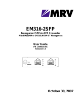
Figure 2 - Connecting Power and Cabling
Connecting DC Power
This section describes how to connect power to the DC version of the LX Series 4008, 4016, and 4032.
The LX-4048 model is made in an AC version only.
Figure 3 - Connecting DC Power
After you have installed the LX-4000 unit, you can connect the DC power as described in the following
procedure (refer to Figure 3):
1. Connect the LX-4000 to the facility's bonding network (or earth ground), using the points on the
rear panel of the LX-4000. The connection to the facility's bonding network should be made per
local practices, using wire with a minimum conductor size of 18 AWG.
2. Using a ¼-inch nut driver, remove the terminal block nuts.
3. Attach the facility’s “A” feed to the terminal block labeled “A”.
100-2 40VAC
1.0A 50/ 60 Hz
10/100 ETHNT
DIAG
100
RCV
100
Mbps
LED
LINK
RCV LINK
TELCO
L INE
9101112 13
14 15 16
1 23 4 5678
10/100
Interface
Modem Port
DIAG Port (Port 0)
9101112 13
14 15 16
1 23 4 5678
25 26 27 28 29 30 31 32
17 18 19 20 21 22 23 24
#10
Grounding
Lugs

451-0312M MRV Communications, Inc. www.mrv.com 3
LX-4000 Quick Start Instructions
NOTE: Be sure that the -48VDC is connected to the minus side, and the 48VDC return is connected to
the plus side.
4. Attach the facility’s “B” feed to the terminal block labeled “B”.
5. Replace the nuts and tighten them securely.
The DC leads should be 22 AWG or larger. They should be terminated with a #5 ring
terminal or larger depending on the wire size used.
NOTE: The LX-4000 will run with only one DC power feed connected. The second input is provided
for redundant system power, which is used in high reliability installations.
6. Attach the clear plastic safety guard to the terminal blocks. (The clear plastic safety guard is
provided with the LX-4000 kit.)
Cabling the LX-4000 Unit
Cable the LX-4000 unit as follows (see Figure 2):
• Connect the 10/100 network cable to the 10/100 port on the rear of the unit. The LINK LED comes
on steady if the cable is properly connected.
• Connect the provided serial port cable to the DIAG port (port 0), and the other end to your
terminal. In LX-4048 units, the DIAG port is on the front (see Figure 4).
• Connect your serial network element devices (terminals, routers, etc.) to the async ports on the
rear of the LX-4000 and power them on.
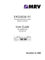
Figure 4 - DIAG Port (Port 0) and Modem Port, LX-4048 Unit Front View
POST Test
The Power On Self Test (POST) runs immediately upon startup. The port status LEDs flicker and the
FLT LED remains on while the test is running (this may take only a few seconds). If the unit passes
the POST test, the FLT LED extinguishes, and the OK LED turns green. If there is a failure, the FLT
LED stays on, and the port status LEDs begin flashing an error code. Refer to Getting Started with
the LX-4000 Series for an explanation of the codes.
DIAG Port (Port 0)
Modem Port
FLT OK 100

LX-4000 Quick Start Instructions
4MRV Communications, Inc. www.mrv.com 451-0312M
Obtaining IP Information
The LX is an intelligent unit; by default the LX attempts to obtain IP information via the DHCP,
BOOTP, or RARP loading methods. If you choose to use these methods, a DHCP, BOOTP, or RARP
server must also be configured on the network to support the LX-4000 unit, as needed. Otherwise, you
can manually configure an IP address. Refer to Getting Started with the LX-Series or to LX-Series
Configuration Guide for further information.
You must first cable the unit according to the instructions in this document or in Getting Started with
the LX-4000 Series.
First Time Quick Configuration
NOTE: Quick configuration runs only at default parameters on the DIAG port (port 0) on all models
when booting from default parameters.
NOTE: Display problems may occur during bootup when you attach a terminal to the DIAG port (port
0) and the display setup is configured to Smooth-2 Scroll. To avoid this, change the scroll
setting to Jump Scroll.
Use the following procedure to configure your LX-4000 unit for the first time.
1. Plug in the terminal at the DIAG port (port 0 - port values are 9600 bps, eight data bits, one stop
bit, no parity, and Xon/Xoff flow control). The Main Menu appears.
2. Press b to boot the LX-4000 unit. The setup takes a minute or two. The “The unit has loaded
to factory defaults, would you like to run Initial Connectivity Setup? y/n”
message appears.
3. Press y (yes) and press Enter. The “Enter your superuser password” message appears,
followed by the Superuser Password prompt.
4. Enter the superuser password system. The Quick Configuration menu appears:
5. Press the number corresponding to the parameter you want to set.
6. Enter the appropriate information and press Enter to return to the Quick Configuration menu.
Once you enter a parameter value, a data entry line specific to that parameter appears on the
Quick Configuration menu.
Quick Configuration menu
1 Unit IP address
2 Subnet mask
3 Default Gateway
4 Domain Name Server
5 Domain Name Suffix
6 Cluster Secret
7 Superuser Password
8 Exit and Save
Enter your choice:

451-0312M MRV Communications, Inc. www.mrv.com 5
LX-4000 Quick Start Instructions
7. Continue in this way through the menu, configuring as many parameters as you want. You are
not required to configure all parameters.
NOTE: You should change the Superuser Password, since this is the first time you are configuring
the LX-4000 unit (the default password is system). Login username and password are case-
sensitive.
8. Press 8 (Exit and Save) to save your changes. The “Is this information correct?”
message appears.
9. Press y (yes) and press Enter. The “Save this information to flash?” message appears.
10. Press y (yes) and press Enter. The information is saved to flash.
11. Press Enter several times to display the Login: prompt. You can now use the LX-4000 unit.
You can access the LX-4000 via the Graphical User Interface (GUI) by typing the unit’s IP address in
your browser. Refer to Getting Started with the LX-4000 Series for more information on how to access
and configure the GUI.
Configuring Server Parameters
The ports on the unit are set to factory defaults. For example, all async ports are set to 9600/8/1/None,
with access remote, xon flow control, and terminal type ANSI. You can change them from the defaults
if you want by connecting to the DIAG port (port 0). This port is set for local access.
Changing the Defaults via the CLI
To change the defaults via the CLI:
1. Enter the default login username (InReach).
2. Enter the default login password (access).
3. At the In-Reach:0> prompt, enter enable. The Password: prompt appears.
4. Enter system or your new Admin password that was set in the Quick Configuration menu. The
Superuser In-Reach:>> prompt appears.
5. Enter config and press Enter. The Configuration prompt Config:0>> appears.
CONFIGURATION SUMMARY
1 Unit IP address 10.80.1.5
2 Subnet mask 255.0.0.0
3 Default Gateway
4 Domain Name Server
5 Domain Name Suffix
6 Cluster Secret Configured
7 Superuser Password Not Changed
8 Exit and Save
Is this information correct? (y/n) :

LX-4000 Quick Start Instructions
6MRV Communications, Inc. www.mrv.com 451-0312M
6. Enter port async 1. The Async 1-1:0>> prompt appears, so you can change port 1
parameters.
7. Press ? or <TAB>. The Port Async Commands list appears. Here you can modify any of the
default port parameters you want.
8. When you are finished making changes, enter end to return to the In-Reach:>> prompt.
9. To save your configuration, enter the command save configuration flash.
Changing the Defaults via the Graphical User Interface
At the Configuration Console window, select Ports: Async. The Async window appears. Here you can
modify any of the port default parameters you want. Refer to Getting Started with the LX-4000 Series
for more information on the Graphic User Interface (GUI).
/