Page is loading ...

June 21, 2023
N116-152 AM-FOG
Version 2.1
AM-FOG Portable FOG Probe

AM-FOG Operation Manual Page 2 Rev. 2.1
Installation and Operation Manual
Contents
1. Introduction ............................................................................................................................................ 3
2. Safety ...................................................................................................................................................... 3
3. Specifications .......................................................................................................................................... 4
4. Principle of Operation ............................................................................................................................ 4
5. What comes with the AM-FOG Probe .................................................................................................... 5
6. Operating the AM-FOG Probe ................................................................................................................ 6
6.1 Downloading the AM-FOG Connect App ........................................................................................ 6
6.2 Getting Started ............................................................................................................................... 7
6.3 Configuring the Probe ..................................................................................................................... 8
6.4 Calibration .................................................................................................................................... 10
7. Taking a Measurement ......................................................................................................................... 11
7.1 Basic Measurement with the Measure Screen............................................................................. 11
7.2 Diagnostics .................................................................................................................................... 12
7.3 Saving Logs .................................................................................................................................... 12
8. Maintenance ......................................................................................................................................... 13
8. Troubleshooting .................................................................................................................................... 14
9. Disposal ................................................................................................................................................. 15
10. Accessories and Spare Parts ............................................................................................................. 15
11. Dimensions ....................................................................................................................................... 16
12. Contact.............................................................................................................................................. 17

AM-FOG Operation Manual Page 3 Rev. 2.1
1. Introduction
The AM-FOG Probe is the first digital analyzer developed to replace core samplers (e.g., Sludge Judge®,
Dipstick Pro®). The probe is portable, robust, customizable and inexpensive. It measures the level of fats,
oils, and grease (FOG) in grease interceptors quickly, accurately, and as cleanly as possible. It records the
results of a measurement for verifiable record keeping. The AM-FOG probe is a game changer for
inspectors, haulers, and food service establishment (FSE) workers who need to know the status of a grease
interceptor quickly and cleanly.
The AM-FOG Probe is the result of five years of intense product development. Other FOG analyzers have
relied on conductance, which suffers from fouling or ultrasonic transducers, which also are impacted by
fouling and are very expensive to build. Because it is based on measuring the electrical properties of the
surrounding medium there are no moving parts or expensive transducers. The coating of the probe changes
the reading very slightly, so fouling is not a major problem. The result is a probe that can withstand the
extreme physical and chemical environment of a grease interceptor. There are other FOG analyzers that
use capacitance, but the AM-FOG uses several ingenious innovations which make the probe robust,
inexpensive, and extremely easy to use.
The length of the AM-FOG probe can be made to any multiple of 8 inches, up to 64”, so that it can be
configured for any grease interceptor except for the very largest gravity interceptors. The embedded
firmware senses the correct length and customizes the user interface on the free downloadable app (AM-
FOG on Google Play or Apple App stores) and works for any probe.
2. Safety
Electrical hazard
Do not open the controller on top of the probe unless you have electrical training and you have read the
instruction manual. The controller contains a 3.6 V battery and a printed circuit board that can be easily
damaged with improper handling.
The probe should not be submerged.
The probe should not be submerged any higher than the top of the sensing tube. The probe is designed
to be robust, but it can be damaged from a fall. Gently place it on its side when the device is not in use.
During calibration, it is recommended to maintain contact with the probe and calibration case to ensure
that it does not tip, even when using the stand.

AM-FOG Operation Manual Page 4 Rev. 2.1
3. Specifications
FOG Model
AM FOG
AM FOG
AM FOG
AM FOG
AM FOG
AM FOG
AM FOG
16
24
32
40
48
56
64
Detection
Water, FOG, air
Extension
Optional
Resolution
2.5 cm (1”)
Wireless transmission
Bluetooth Low Energy
(BLE)
Measurement
Length
16” to 64” in 8”
increments
Transmission Range
5-10 m
Alarm Indicator
Default—25% Rule
User Interface
App for Android and
iOS
Calibration
Two points: Water and Air.
Operation Modes
Calibrate, Run,
Configuration
Wetted Materials
PVC, PLA
Battery
Lithium Metal: 3.6 V,
950 mAh
Ingress
IP65
Temperature
-10 to 60 °C
Cleaning
Integrated wiper, optional
disinfection wipes
pH Range
2 to 12
Transportation
Carrying case (PVC).
Doubles as water
container for calibration
Status Indicator
LED
Extension
Acme thread. Accepts
most extension poles
Cleaning
Squeegee integrated
into carrying case.
4. Principle of Operation
The AM-FOG Probe does not actually measure air, water, or FOG. It’s important to understand this point
so there is no misunderstanding about what the probe is actually doing. It cannot actually distinguish
between air, water, or FOG. Instead, the AM-FOG Probe works by measuring the capacitance of the
surrounding medium.
Capacitance is related to an electrical property called the dielectric constant. Materials that hold a large
charge, such as air, have a high dielectric constant. Those that don’t, such as water, have a low dielectric
constant. The dielectric constant of FOG is lower than air but higher than water.
The AM-FOG Probe uses electrodes whose electric fields extend several centimeters into the medium to
measure capacitance. The probe consists of a number (1 to 8) of 8” sensor boards attached in series, with
each board containing 8 capacitance sensing elements located at 1” intervals. The probe length can be
anywhere from 16” to 64”, with 1” resolution, regardless of size. The probe can effectively measure FOG
in any type of grease interceptor regardless of type (e.g., hydromechanical, gravity, or grease removal
device).

AM-FOG Operation Manual Page 5 Rev. 2.1
Firmware inside the probe communicates via Low Energy Bluetooth (BLE) to an app on a smart phone or
tablet. The app is free and available for both Android and iOS (iPhone) devices. Configuration, calibration,
and measurement are all done on the app. Search for AM-FOG on your Google Play or Apple App stores.
The value of the capacitance that the probe reads is in units of frequency (Hz). The process of calibration
accomplishes two goals:
1. It minimizes the differences between sensors and improves the precision of the measurement.
2. It resets the measurement range from Hz to an arbitrary scale of 0 to 10,000, in which 0 is the value
for tap water and 10,000 is the value for water.
An algorithm has been developed to convert the raw frequency measurements into a more manageable
working range. Typical capacitance values fall into the following algorithmically calculated ranges:
AM-FOG Analyzer Default Capacitance Ranges
Air
8,000 – 11,000
FOG
3,000 – 8,000
Water/Sludge
0 – 3,000
To ensure accurate readings during inspection the AM-FOG Probe needs to be calibrated periodically. The
calibration process is necessary for both air and water and the process is managed through the app. You
cannot “over calibrate” a probe so repeating the process multiple times will only enhance the accuracy of
its measurements.
5. What comes with the AM-FOG Probe
The AM-FOG probe is a self-contained unit and has no accessories that are necessary for operation. The
only other component needed is the free app loaded onto your smart phone. The handle of the probe will
enable you to immerse the probe in the interceptor.

AM-FOG Operation Manual Page 6 Rev. 2.1
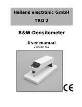
The probe comes with a 3” diameter PVC carrying case—shown
on the left. The carrying case doubles as a container for
calibrating the probe in water. A stand is included to enable the
probe to be free-standing, but it is not meant to be used
unattended for periods of time.
If you need to access an interceptor that is buried, there is a
recessed ACME female thread in the controller. Any extension
pole that has a male ACME threaded end will screw into the
controller, e.g., a painter’s extension pole.
To wipe down the probe, it comes equipped with a squeegee
with a handle and a built-in rubber wiper. Just pull the handle
down the length of the probe to remove caked-on FOG for quick
and easy cleanup. Finish up by wiping the probe down with a
wet wipe and paper towel.
6. Operating the AM-FOG Probe
6.1 Downloading the AM-FOG Connect App
The interface to the probe is through an app on an Android or iOS (Apple) phone. The
app is free. We are constantly adding useful features so keep checking the app store for
the latest version.
For an Android phone go to the Play Store and look for AM-FOG. For an iPhone go to the
App Store.
The app does NOT connect to the internet. Therefore, it collects zero information from you to send to us or
anyone else so you can rest assured that there is no risk to the privacy or you or your organization in
downloading and using the app.

AM-FOG Operation Manual Page 7 Rev. 2.1
6.2 Getting Started
1. Turn on the probe by pressing the power button. The
green LED surrounding it will blink. If nothing happens
then it’s possible that the battery came loose during
shipment. If you open the cover of the head enclosure
you will see the battery and its connector.
2. Launch the app. Just press the AM-FOG app icon.
3. The first time the app is used you will be prompted to
allow the use of Bluetooth. Click “ok” to allow the app
to talk to the probe through a Bluetooth connection.
4. Press the SCAN button on the bottom of the initial
screen. It and will search for the Bluetooth signal
from the probe.
5. When the app finds the probe, a new screen will
display prompting the user to Select the device to
connect to.
6. If there is more than one probe powered on, the
screen will list all those probes, but with the same
description for each. This can make picking the
“right” probe more difficult, therefore we
recommend only turning on the probe you want to
connect to.
7. Upon successful connection the Configuration
screen will appear.
Power
AM-FOG
App
If the Probe
is “on” it
will show
up here.
Touch to
select the
probe
Press
Scan

AM-FOG Operation Manual Page 8 Rev. 2.1
6.3 Configuring the Probe
Successful connection with the probe automatically
brings up the Configuration screen. There are six
functions in the app: Measure, Diagnostics, Calibrate,
Configuration, View Logs, and Advanced Settings. They
are accessed by clicking on the menu icon in the upper
left corner (three horizontal bars).
The top of the Configuration screen allows you to
personalize the probe and the location you are sampling.
The first time you connect the app to a probe you will
want to change the Probe Description and enter the
serial number for the probe (printed on the label on top
of the probe housing). The information entered will be
saved for each probe you link to so that each will be
identifiable by the app.
The Location information is intended to be set by the
user according to user preference. All three fields are
just text fields in which a limited amount of information can be saved. It may be useful to capture the name
of the inspector, the name of the FSE, the location of the grease interceptor onsite, or any other
information the user deems important.
The bottom of the Configuration screen contains the Set Points for the probe. The factory default settings
for the probe may or may not be accurate for your specific location. Readings may be affected by
elevations, ambient temperatures, humidity, and so on. Therefore, you may need to adjust the ranges to
improve accuracy of measurements for your area.
Before adjusting the set points, you should calibrate the probe for air and water first. This will reset all of
the values in the firmware for the probe for your area. Once calibrated, you can check to see what the
effective ranges for air and water are and this will allow you to determine the effective range for FOG.
The “typical” ranges for air, FOG, and water are as follows:
Scaled Value
Component
Color
8000 - 11000
Air
3000 to 8000
FOG
<3000
Water
N/A
Spacer*
*Note, the bottom one-inch inside the probe contains a spacer that absorbs the weight and supports the
column of sensors. There is no sensor in this space.

AM-FOG Operation Manual Page 9 Rev. 2.1
To validate the set points, go to the Menu and click on
Diagnostics. This will take you to the Diagnostics screen.
Here you will see five columns:
Sensor = each sensor inside the probe numbered from the
top down
Height (in) = the total height of the probe as measured
from the bottom up, beginning with 2” at the final sensor,
since there is no sensor in the bottom 1” of the probe
Scaled Frequency = the algorithmic calculations for Air,
FOG, and Water
Frequency (comp.) = the value of the capacitance that the
probe reads in units of frequency (Hz)
Temp (0C) = ambient temperature around the probe in
the marked sections of sensors; affected by surroundings
and will change for those sensors affected when
submersed in an interceptor.
For the purposes of checking the set point values, hold the probe in the air and make note of the Scaled
Frequency range of values displayed (image to the left above). In the image provided you can see the range
is from 9,700 on the lower end to over 10,000 on the upper end of the range. The lower end can be closer
to 9,000 and the upper end over 11,000, routinely.
Once the air values have been verified take a 5-gallon bucket and fill it “mostly” full of water from the tap.
Dip the probe in and rest it on the bottom of the bucket for a minute or so (longer is fine). Again, make
note of the Scaled Frequency range of values displayed (image to the right above). In the image provide
you can see the range is from -500 on the lower end to 173 on the upper end. The lower end may or may
not be below zero and the upper end can be as high as 2,000, routinely. In some cases, the upper range
can be as high as 2,500 or even a bit higher.
These range checks give us the upper and lower values
for Air and Water. FOG falls between these ranges. To
change the set points, start with water. Touch the value
shown Water (max). and it will allow you to change it. Set
the upper limit for water, which is by default the lower
limit for FOG. Thus, we want to set the value at a safe
lower limit for FOG. 3,000 works well, typically, and is the
default value.
Next touch the value range for FOG (min to max), which
allows you to change the upper limit for FOG, which
corresponds to the lower limit for air. The probe is preset
at 8,000, however, that value may be too low for many
areas. If the lower limit for air in your area is consistently
over 9,000, you may want to change this value to 9,000.
Finally, the only thing effected by changing these values
is which colors apply to the ranges you want. Color coding

AM-FOG Operation Manual Page 10 Rev. 2.1
is offered to present the Air, FOG, and Water levels as a visual aide. You can change these as often as
necessary to ensure the most accurate visual presentation.
6.4 Calibration
As with any sensor, two points are required to calibrate
the FOG probe. The firmware converts the frequency
values from the sensors into arbitrary values called
Scaled Frequency, such that 0 represents the lowest
scaled frequency value (water) and 10,000 represents
the highest scaled frequency value (air).
Calibrating the probe in Water requires a container at
least as deep as the probe. The 3” diameter carrying case
doubles as a reservoir for water calibration. Simply fill the
carrying case with water and submerge the probe. A
larger/wider container may give slightly better accuracy.
During Air calibration, hanging or holding the probe in air
is sufficient. Keep the probe at least 2” away from any
surface.
To conduct a calibration of the probe, press the menu
icon in the top left and bring up the menu screen and
select Calibration.
Follow these instructions for Water:
1. Immerse the probe in a bath of water up to the top of the PVC pipe. (Do NOT immerse the head
unit.) The carrying case that comes with the probe can be filled with water for convenient
calibration.
2. Allow about a minute for the probe to equilibrate in water.
3. Press the Water Calibration button.
4. When the Alert window appears select Calibrate. This starts the one-minute calibration.
5. The Calibration screen will return.
Follow these instructions for Air:
1. Hang the probe in the air for at least one minute to let the probe equilibrate.
2. Press the Air Calibration button.
3. When the Alert window appears select Calibrate. This starts the one-minute calibration.
4. The Calibration screen will return.
Note that the Calibration screen reports the results of the calibration: the date of both calibrations and the
slope and the intercept of the graph that converts frequency values to the calibrated range of 0 to 10,000.

AM-FOG Operation Manual Page 11 Rev. 2.1
7. Taking a Measurement
7.1 Basic Measurement with the Measure Screen
To conduct a measurement of the FOG layer in a grease interceptor, press the
menu icon in the top left and bring up the menu screen and select Measure. The
primary screen that you will see is the Measure screen. This is a simple bar graph
that is color coded as follows:
When you are ready, dip the probe into the grease interceptor, straight down (as
little angle as possible). Do not submerge the head assembly of the probe, which
is where the electronic components are located.
If the probe is able to touch the bottom of the grease interceptor, you will get an
accurate measurement for the percentage of FOG and the height of the FOG
layer.
It’s important to let the probe sit in the grease interceptor for a minute or so
because when it is first submerged it will drag some FOG down into the water
area, which needs time to resettle into the FOG layer.
The app calculates the total height of the static water and assumes that the probe
is touching the bottom of the grease interceptor in the calculation. If the probe is
not touching the bottom, then disregard the calculated percentage as it will not
be accurate. A red triangle appears if more than 25% of the volume of the
interceptor is occupied by FOG, but again, this will not be accurate if the probe is
not actually touching the bottom of the grease interceptor.
Component
Color
Air
FOG
Water
Spacer*

AM-FOG Operation Manual Page 12 Rev. 2.1
7.2 Diagnostics
The Measure screen displays the data captured during an
inspection as a simple graph, while the Diagnostics
screen provides the actual data captured during an
inspection. To access the Diagnostics screen, press the
menu icon in the top left and bring up the menu screen
and select Diagnostics.
The same color coding is used in the Diagnostics screen
to make it easier to see the different layers of Air, FOG,
and Water.
The Diagnostics screen is also
reachable by clicking on the
waveform icon that sits next to
the Save icon on the Measure
screen, just above the
“Measured Height” data.
7.3 Saving Logs
The Measure screen is presented in a simple graphical
manner to make presenting the condition of the grease
interceptor to the FSE easy and easy to understand. A
screen shot of the measurement can be saved as part of
the record for the inspection.
There is a “save” button to the right and just above the
“measured height” and percentage calculations. This will
create a Log that is saved to the smart phone or tablet.
You can access theses logs by pressing the Menu icon and
selecting View Logs.
The View Logs screen shows all of the logs that have been
saved to the device. You can then select the log you wish
to view from this list.
Shortcut to
Diagnostics Screen

AM-FOG Operation Manual Page 13 Rev. 2.1
The Log you select to view will bring up a separate
window like the screen shot image here (left). It will
contain the same information that is displayed on the
Diagnostics screen along with the “measured height” and
percentages information that is shown on the Measure
screen.
Each Log records the GPS location where it was saved.
Clicking on the link will open your maps program showing
the exact location of the inspection by latitude and
longitude. This makes it easy to connect a Log to a given
record for an FSE.
At the top right of the app is the upload icon, which looks
like this:
Clicking the upload icon brings up a separate window, shown above (right), which allows you to text the
Log, email it, or even share it to social media. This is your permanent Log for the inspection so save it as
appropriate with the records for the FSE.
8. Maintenance
The maintenance is simple. After testing simply slide the “squeegee” wiper down the probe to remove
any residual fats, oils or greases from the testing. The design of the probe and cleaning process is
intended to keep the user clean. It is recommended to also use on both the probe and the “squeegee” a
sanitizing wipe after usage or it can be cleaned with a hot water rise it mild soap or vinegar.
Danger of damage to the instrument due to inappropriate cleaning agents!
The head enclosure and probe are made of PVC. This material can be sensitive to some organic
solvents, If liquids enter the head enclosure they can damage the instrument.
1. Use only water and a mild detergent to clean the housing.
2. Wipe off any spills immediately.

AM-FOG Operation Manual Page 14 Rev. 2.1
The battery powering this probe is considered a consumable item. Please reference section 7 on
disposal. The Battery in the AM FOG is a Lithium Metal Battery and should only be disposed of according
to local regulations. Shipping of this type of battery is prohibited by air in the US.
When replacing the battery, to reduce the risk of injury, the user must read the instruction manual prior
to use. Use only with battery from Water Analytics. Always use proper PPE. To protect the device, the
probe must be stored properly, and the head enclosure should not be submerged. If this has occurred,
precautions should be taken by a trained professional to remove and replace the lithium metal battery.
The replacement of the battery is simply done by removing the 4 screws of the head enclosure and
disconnecting the snap connector of the battery. Then the battery can be removed by hand or with the
appropriate tool. The new battery is simply inserted into the battery holder and the snap connector can
then be engaged (Note: there should only be one way to connect, but if the female mating snap
connector is missing or broken, please contact the Water analytics team for further troubleshooting).
8. Troubleshooting
1. You press the power button, but the LED does not blink and the probe does not appear in the
app.
Either the battery is dead or it came loose during shipment. If you open the cover of the head
enclosure you will see the battery and its connector. If the battery is properly connected then it
needs to be replaced.
2. The probe connects to the app, but the Measure and Diagnostics screens fail to show any
sensor values.
Communication between the sensors and the controller has been lost. The cause may be as
simple as the ribbon cable connecting the controller board disconnecting from one of the two
ends or it could be a failure of one or more of the sensor circuit boards. A snap connector may
have become loose during shipment.
3. The FOG and water levels shown on the Measure screen don’t look correct or don’t agree with
a core sampler.
The probe’s calibration might be obsolete and need to be updated. A simple test to verify this is
to simply hold the probe in air and check the scaled values in the Diagnostics screen. The values
should be between 9000 and 11,000. Alternatively, you can insert the probe into the case filled
with water. Those values should be between -1000 and 1000. If not, then calibrate the probe in
both air and water. (If you’re checking the probe output in water it only takes an extra minute to
calibrate it in water.)
If the values in the Diagnostics screen are reasonable then the color coding does not reflect the
actual composition of the trap. For instance, the app might show 1” of FOG and you are certain
the FOG layer is thicker. That can happen you set the FOG range in the Configuration screen to
be 3000 to 8000 but the Diagnostics screen shows a value of, say, 2800. If you were to change

AM-FOG Operation Manual Page 15 Rev. 2.1
the FOG range to 2000 to 8000 then the app would show 2” of FOG. Always let the Diagnostics
screen be your guide.
4. The Measure and Diagnostics screens look unusual when you first insert the probe and then
starts to change in the direction you expected.
At some grease interceptors, the viscosity of the FOG may be such that the FOG layer may
temporarily adhere to the probe during insertion. In these cases, leave the probe inserted for a
few minutes to ensure that the FOG has settled. This will occur in colder environments,
especially as the FOG layer approaches freezing.
5. If the Connecting icon continues ad infinitum
The probe timed out. Just restart the connection process. If the Connecting icon
continues to spin, then the controller board in the head of the probe has lost
contact with the sensor boards in the probe. The likely cause is that the ribbon
cable that connects the controller board to the top sensor board has disconnected.
If problems persist, contact us at support@wateranalytics.net or call us at 978-749-994.
9. Disposal
In accordance with local regulations, please dispose of this product at specified locations for electrical
and electronic equipment. Please contact the local government/authority or party responsible from
which you purchased this device. Should this device be passed on to other parties (for private or
professional use), the content of this regulation must also be related.
10. Accessories and Spare Parts
Part Number
Description
C1-FOG-POLE (AM-FOG-POLE)
Extension pole with an Acme thread
A50-18
Replacement Battery (Lithium Metal: 3.6 V, 950
mAh) (Ground ship only)
C1-FOG-WIPER (AM-FOG-WIPER)
Squeegee Wiper
A29-362
Replacement Stand
C1-FOG-CASE-24
Calibration case suitable for AM-FOG 16,24
C1-FOG-CASE-40
Calibration case suitable for AM-FOG 32,40
C1-FOG-CASE-54
Calibration case suitable for AM-FOG 48,54
C1-FOG-CASE-64
Calibration case suitable for AM-FOG 64

AM-FOG Operation Manual Page 16 Rev. 2.1
11. Dimensions

/