Page is loading ...

Operating Instructions
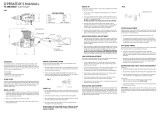
Universal drilling and milling machines
with linear guideways
F1410 LF F1410 LF high speed
CC-F1410 LF CC-F1410 LF high speed
Walter Blombach GmbH
Tool and Machine Factory
D-42899 Remscheid Am Blaffertsberg 13 Phone: 0049 (2191) 597-0 Fax: 0049 (2191) 597-40 E-Mail: [email protected]
D-54673 Neuerburg WABECO Str. 1-10 Phone: 0049 (6564) 9697-0 Fax: 0049 (6564) 9697-25 E-Mail: neuerburg@wabeco-remscheid.de
www.wabeco-remscheid.de

2
Index
EC-Conformity Declaration 5
1. Product range
1.1 F1410 LF with trapezoid thread spindle 8
1.2 F1410 LF high speed with trapezoid thread spindle 10
1.3 F1410 LF with ball bearing spindle 12
1.4 F1410 LF high speed with ball bearing spindle 14
1.5 CC-F1410 LF 16
1.6 CC-F1410 LF high speed 18
2. Technical Data 20
2.1 Dimensions 21
3. Drawings and list of parts
3.1 Protective cover with electrical equipment for F1410 LF 22
3.1.1 List of parts protective cover with electrical equipment for F1410 LF 23
3.2 Protective cover with electrical equipment for CC-F1410 LF 24
3.2.1 List of parts protective cover with electrical equipment for CC-F1410 LF 25
3.3 Protective cover 26
3.3.1 List of parts protective cover 26
3.4 Milling head with 1,4 kW motor for F1410 LF and CC-1410 LF 28
3.4.1 List of parts for milling head with 1,4 kW motor for F1410 LF and CC-1410 LF 29
3.5 Milling head high speed with 2,0 kW motor for F1410 LF high speed 30
3.5.1 List of parts for milling head with 2,0 kW motor for F1410 LF high speed 31
3.6 Milling head with 2,0 kW motor for CC-F1410 LF high speed 32
3.6.1 List of parts for milling head with 2,0 kW motor for CC-F1410 LF high speed 33
3.7 Base machine F1410 LF with trapezoid thread spindle 34
3.7.1 List of parts for base machine F1410 LF with trapezoid thread spindle 35
3.8 Base machine F1410 LF with ball bearing spindle 36
3.8.1 List of parts for base machine F1410 LF with ball bearing spindle 37
3.9 Base machine CC-F1410 LF 38
3.9.1 List of parts for base machine CC-F1410 LF 39
3.10 Vertical slide F1410 LF with trapezoid thread spindle 40
3.10.1 List of parts vertical slide F1410 LF with trapezoid thread spindle 41
3.11 Vertical slide F1410 LF with ball bearing spindle 42
3.11.1 List of parts vertical slide F1410 LF with ball bearing spindle 43
3.12 Vertical slide CC-F1410 LF 44
3.12.1 List of parts vertical slide CC-F1410 LF 45
3.13 Top slide F1410 LF with trapezoid thread spindle 46
3.13.1 List of parts for top slide F1410 LF with trapezoid thread spindle 46
3.14 Top slide F1410 LF with ball bearing spindle 47
3.14.1 List of parts for top slide F1410 LF with ball bearing spindle 47

3
Index
3.15 Top slide CC-F1410 LF 48
3.15.1 List of parts for top slide CC-F1410 LF 49
3.16 Cross slide F1410 LF with trapezoid thread spindle 50
3.16.1 List of parts for cross slide F1410 LF with trapezoid thread spindle 50
3.17 Cross slide F1410 LF with ball bearing spindle 51
3.17.1 List of parts for cross slide F1410 LF with ball bearing spindle 51
3.18 Cross slide CC-F1410 LF 52
3.18.1 List of parts for cross slide CC-F1410 LF 52
3.19 Y-spindle F1410 LF with trapezoid thread spindle 53
3.19.1 List of parts for Y-spindle F1410 LF with trapezoid thread spindle 53
3.20 Y-spindel CC-F1410 LF with ball bearing spindle 54
3.20.1 List of parts for Y-spindle F1410 LF with ball bearing spindle 54
3.21 Y-spindle CC-F1410 LF 55
3.21.1 List of parts for Y-spindle CC-F1410 LF 55
3.22 Arm for control station 56
3.22.1 List of parts for the arm of control station 56
3.23 Control station milling plus 1,4 kW 58
3.23.1 List of parts for control station milling plus 1,4 kW 59
3.24 Control station milling plus 2,0 kW 60
3.24.1 List of parts for control station milling plus 2,0 kW 61
3.25 Control station nccad 1,4 kW 62
3.25.1 List of parts for control station nccad 1,4 kW 63
3.26 Control station nccad 2,0 kW 64
3.26.1 List of parts for control station nccad 2,0 kW 65
3.27 Mounting for linear measuring scales 66
3.27.1 List of parts for mounting linear measuring scales 67
4. Circuit diagram
4.1 Motor 1,4 kW 68
4.2 Motor 2,0 kW high speed 69
4.3 Motor 1,4 kW with safety cabin 70
4.3.1 Motor 2,0 kW high speed with safety cabin 71
4.4 Drive motor of the CNC control 72
4.5 Motor 1,4 kW nccad control 73
4.5.1 Motor 2,0 kW high speed nccad control 74
5. Delivery and installation 75
6. Starting-up and maintenance 76
7. Safety devices and recommendations 79
7.1 CC-F1410 LF with safety machine cabin 81

4
Index
8. Clamping and ejecting tools 82
9. Adjustment of the r.p.m. 84
9.1 Adjustment of the r.p.m. values for working aluminium and steel 84
9.2 Adjustment of the r.p.m. for 1,4 kW motor 84
9.3 Adjustment of the r.p.m. for 2,0 kW motor (high speed) 85
10. Feed motion
10.1 Feed motions X, Y and Z-axis 86
11. Recommendations for application and operation 87
11.1 Swivelling of the milling head 88
12. Unit for lubrication coolant 89
13. Declaration of noise levels 90
14. Disposal of the drilling and milling machine 90

5
EC – Conformity Declaration
In the name of the manufacturer
Walter Blombach GmbH
Tool and Machine Factory
based in Remscheid and Neuerburg
D-42871 Remscheid Postfach 12 01 61 Phone: 0049 (2191) 597-0 Fax: 0049 (2191) 597-40
D-54673 Neuerburg WABECO Str. 1-10 Phone: 0049 (6564) 9697-0 Fax: 0049 (6564) 9697-25
we hereby declare that the universal milling and drilling machines specified below
Universal milling and drilling machine type:
F1410 LF
F1410 LF high speed
CC-F1410 LF
CC-F1410 LF high speed
meet the following regulation requirements for standard serial production:
- directive for machines 98/37 EG
- low voltage directive 73/23/EWG
- EMV directive 89/336/EWG
In order to meet / implement the requirements of the above mentioned directives, the following
applicable and previously published standards have been adhered to:
EN ISO 12100-1
EN ISO 12100-2
EN 12840
EN 60204-1
D-54673 Neuerburg
________________________________
City
Signature

6
Dear customer!
Congratulations on choosing the WABECO Universal Drilling and Milling Machine. We have
devoted great care in its manufacture and it has passed a thorough quality control test. These
operating instructions are to help you to work with it safely and properly. Therefore we request that
you read the respective instructions carefully and follow them exactly.
After unpacking the machine please check to see if any kind of damage has occurred during
transportation. Any complaints must be lodged immediately. Complaints made at a later date
cannot be accepted.
If you have any questions or need any spare parts, please state the machine number located
on the front of the motor (see rating plate).

7

8
1 Product range
1.1 F1410 LF with trapezoid thread spindle

9
1 Product range
1.1 F1410 LF with trapezoid thread spindle
1) Base machine
see 3.7 page 34 2) Cross slide
see 3.16 page 50 3) Top slide
see 3.13 page 46 4) Vertical slide
see 3.10 page 40
5) Y-spindle
see 3.19 page 53 6) Protective cover
see 3.3 page 26
7) Protective cover with
electrical equipment
see 3.1 page 22
8) Milling head
siehe 3.4 Seite 28

10
1 Product range
1.2 F1410 LF high speed with trapezoid thread spindle

11
1 Product range
1.2 F1410 LF high speed with trapezoid thread spindle
1) Base machine
see 3.7 page 34 2) Cross slide
see 3.16 page 50 3) Top slide
see 3.13 page 46 4) Vertical slide
see 3.10 page 40
5) Y-spindle
see 3.19 page 53 6) Milling head
see 3.5 page 30 7) Protective cover
see 3.3 page 26

12
1 Product range
1.3 F1410 LF with ball bearing spindle

13
1 Product range
1.3 F1410 LF with ball bearing spindle
1) Base machine
see 3.8 page 36 2) Cross slide
see 3.17 page 51 3) Top slide
see 3.14 page 47 4) Vertical slide
see 3.11 page 42
5) Y-spindle
see 3.20 page 54 6) Protective cover
see 3.3 page 26
7) Protective cover with
electrical equipment
see 3.1 page 22
8) Milling head
see 3.4 page 28

14
1 Product range
1.4 F1410 LF high speed with ball bearing spindle

15
1 Product range
1.4 F1410 LF high speed with ball bearing spindle
1) Base machine
see 3.8 page 36 2) Cross slide
see 3.17 page 51 3) Top slide
see 3.14 page 47 4) Vertical slide
see 3.11 page 42
5) Y-spindle
see 3.20 page 54 6) Milling head
see 3.5 page 30 7) Protective cover
see 3.3 page 26

16
1 Product range
1.5 CC-F1410 LF

17
1 Product range
1.5 CC-F1410 LF
1) Base maschine
see 3.9 page 38 2) Cross slide
see 3.18 page 52 3) Vertical slide
see 3.12 page 44 4) Top slide
see 3.15 page 48
5) Arm for control
mechanism
see 3.22 page 56
6) Control station
see 3.23,3.25 page 58 7) Y-spindle
see 3.21 page 55 8) Milling head
see 3.4 page 28
9) Protective cover
see 3.3 page 26
10) Protective cover
with electrical
equipment
see 3.2 page 24

18
1 Product range
1.6 CC-F1410 LF high speed

19
1 Product range
1.6 CC-F1410 LF high speed
1) Base machine
see 3.9 page 8 2) Cross slide
see 3.18 page 52 3) Vertical slide
see 3.12 page 44 4) Top slide
see 3.15 page 48
5) Arm for control
mechanism
see 3.22 page 56
6) Control station
see 3.24,3.26 page 58 7) Y-spindle
see 3.21 page 55 8) Milling head
see 3.6 page 32
9) Protective cover
see 3.3 page 26

20
2 Technical Data
Dimensions of the milling and drilling machine
installation area (trapezoid thread)………................ width 1415 mm x depth 705 mm
installation area (ball bearing spindle)....................... width 1415 mm x depth 875 mm
height 1,4 kW............................................................ 950 mm
height 2,0 kW .......................................................... 1100 mm
Working area
Longitudinal travel X-axis ......................................... 500 mm
Transverse travel Y-axis ........................................... 200 mm
Vertical travel Z-axis ................................................. 280 mm
Work table – cross table
length x width ........................................................... 700 x 180 mm
number of T-slots...................................................... 3
Milling head
swivelling range ....................................................... 90° both sides
tool holder ................................................................. MT2 optional MT3 or SK30
tool clamping ............................................................ In-house innovation for clamping and ejecting
tools
drilling stroke ......................................................... 55 mm
Distance milling table work spindle
min. ........................................................................ 65 mm
max. ....................................................................... 350 mm
working range spindle nose –support……………….. 185 mm
Electrical equipment (for F1410 LF)
drive ......................................................................... single-phase inverse-speed motor as direct
current model infinitely variable with
continuous r.p.m. surveillance
nominal voltage, frequency ...................................... 230V, 50 Hz
consumption ............................................................ 6A
service output .......................................................... 1,4 kW
tool spindle………..................................................... 140-3000 r.p.m.
Electrical equipment (for F1410 LF high speed)
drive ........................................................................ motor with frequency converter
infinitely variable with continuous r.p.m.
surveillance and clockwise and anticlockwise
rotation
nominal voltage, frequency ...................................... 230V, 50 Hz
consumption ............................................................ 8,6 A
service output .......................................................... 2,0 kW
tool spindle……......................................................... 100-7500 r.p.m
Feed motors (hybrid-step motors)
voltage .................................................................... 2,9 VDC
current .................................................................... 1,7 A
torque resistance..................................................... 1 Nm
number of stepps per rev. ...................................... 200
angle of step........................................................... 1,8°
- Technical details are subject to change -
/