Projectiondesign F22 User manual
- Category
- Data projectors
- Type
- User manual


english
3
A
TABLE OF CONTENTS
ATable of contents
BIntroduction
CSafety & Warnings
DSupplied material
EOptional lenses
FOverview
GKeypad
HIndicators
IRemote control
JConnector panel
KSet up
LImage adjustments
MLamp operation
NPin Code
OCeiling mount
PUsing the projector
QMenu system
RRS 232 and LAN control
STrouble shooting
TMaintenance
UService information
VLamp change
WTechnical data
XDeclarations
03
04
04
07
08
09
10
11
12
14
15
16
17
17
18
20
21
29
29
30
30
31
32
36
Downloaded from ProjectorsManual.com Manuals

english
4
B
INTRODUCTION
This digital projector is designed with the latest state-of-the-art
technologies in illumination, imaging, optics, electronics, thermal and
industrial design in order to serve traditional as well as novel imaging
applications across a variety of markets, offering features such as:
- PROFESSIONAL GRADE POWERED PROJECTION LENSES with
bayonet mounts
- DUAL LAMP SYSTEM with separate lamps for improved life,
redundancy and 24/7 operation
- DUAL OPTOMECHANICAL IRIS for variable contrast and
brightness
- MECHANICAL SHUTTER for total black
- SXGA+ 1400x1050 pixel DLP™ technology
- SINGLE CHIP DMD™ with DarkChip3™ technology by Texas
Instruments®
- HIGH CONTRAST for vibrant colors and deep blacks
- HIGH RESOLUTION for unprecedented detail
- HIGH BRIGHTNESS for larger screens
- DEEP BLACKS for maximum dynamics
- REDUCED IMAGE NOISE through high end signal processing
- FAROUDJA DCDi™ Video processing and de-interlacing
- ECO MODE for reduced power consumption and lower audible
noise
- VARIABLE LAMP POWER for alignment of multi-screen
configurations
- LONG LIFE LAMP (up to 4000 hours) in low power ECO mode
- STYLISH AND COMPACT DESIGN to fit most applications,
installed or movable
- MULTIPLE LENS OPTIONS for close-up front or rear projection
and other applications
- SIX VIDEO and GRAPHICS INPUTS for virtually any video and data
source
- TWO EXPANSION PORTS for application specific signal
processing
- LAN, RS232 and USB ports for control and monitoring
The specifications and functionality of the product may change
without prior notice.
SAFETY & WARNINGS
This user guide contains important information about safety
precautions and the set-up and use of the projector. Please read the
manual carefully before you operate the projector.
SAFETY
This device complies with relevant safety regulations for data
processing equipment for use in an office environment. Before using
the projector for the first time, please read the safety instructions
thoroughly.
WARNING
Use only the cables and cords supplied with the projector or original
replacement cables. Using other cables or cords may lead to
malfunction and permanent damage of the unit.
Always use 3-prong / grounded power cord to ensure proper
grounding of the unit. Never use 2-prong power cords, as this is
dangerous and could lead to electrical shock.
Never open the unit. The projector contains no user serviceable parts.
Refer all repairs to qualified personnel only.
Make sure that no objects enter into the vents and openings of the set.
Do not spill any liquids on the projector or into the vents or openings
of the unit.
Always remove lens cap before switching on the projector. If the lens
cap is not removed, it may melt due to the high energy light emitted
through the lens. Melting the lens cap may permanently damage the
surface of the projection lens.
Do not look into the projection lens when the projector is switched on.
The strong light may permanently damage sight.
Do not look into the laser beam when activated on the remote control.
Laser light may permanently damage sight. Do not point laser beam
on people.
Only place the projector on a stable surface, or mount it securely using
an approved ceiling-mount.
Do not drop the projector.
Always operate the projector horizontally, within the range of the
adjustable rear feet. Operating the unit in other positions may reduce
lamp life significantly, and may lead to overheating, resulting in
malfunctioning.
Always allow ample airflow through the projector. Never block any of
the air vents. Never cover the unit in any way while running. Allow for
sufficient distance to walls and ceilings to avoid overheating. Minimum
safety distance to any side of the unit is 50 cm / 20" in any direction.
CAUTION! Hot air is exhausted from the rear vent. Do not place
objects that are sensitive to heat nearer than 50cm / 20" to the
exhaust vent.
The projector is designed for indoor use only. Never operate the unit
outdoors.
english
C
Downloaded from ProjectorsManual.com Manuals

english
5
SAFETY & WARNINGS
Do not operate the projector outside its temperature and humidity
specifications, as this may result in overheating and malfunctioning.
Only connect the projector to signal sources and voltages as
described in the technical specification. Connecting to unspecified
signal sources or voltages may lead to malfunction and permanent
damage of the unit.
Allow the unit to cool down for 60 minutes before lamp change.
INFORMATION AND WARNING ABOUT POTENTIAL HEALTH
ISSUES RELATED TO MERCURY VAPOR.
This projector uses a very powerful UHP™ lamp for illumination to
produce an extremely bright image.
This technology is similar to other high-pressure discharge lamps that
are extensively used in cars, street lights and other lighting appliances
today. These lamps, like fluorescent lighting, contain small amounts of
mercury. The amount of mercury present in a lamp is far below the
limits of danger set by the authorities.
It is very important that lamps containing mercury are treated properly
to minimize potential health hazards.
The UHP™ lamp, like any other high brightness projector lamp, is
under high-pressure when operating. While the lamp and the projector
are carefully designed to minimize the probability of lamp rupture, the
lamp may break while operating and small amounts of mercury vapor
may be emitted from the projector. The probability of rupture increases
when the lamp reaches its nominal life. It is therefore highly
recommended that the lamp is replaced when the rated lifetime is
reached.
As a general precaution, secure good ventilation in the room when
operating the projector. If lamp rupture occurs, evacuate the room and
secure good ventilation. Children and pregnant women in particular
should leave the room.
When replacing a worn lamp, dispose of the used lamp carefully by
proper recycling.
Mercury is a naturally occurring, stable metallic element that may pose
a safety risk to people under certain conditions. According to the
Public Health Statement for Mercury published by the Agency for Toxic
Substances and Disease Registry ("ATSDR", part of the United States
Public Health Service), the brain, central nervous system and kidneys
are sensitive to the effects of mercury, and permanent damage can
occur at sufficiently high levels of exposure. Acute exposure to high
concentrations of mercury vapor can cause conditions such as lung
and airway irritation, tightness in the chest, a burning sensation in the
lungs, coughing, nausea, vomiting and diarrhea. Children and fetuses
are particularly sensitive to the harmful effects of metallic mercury to
the nervous system.
Seek medical attention if any of the above symptoms are experienced
or if other unusual conditions are experienced following lamp rupture.
SAFETY & WARNINGS
WARNING LEAD
This product contains chemicals, including lead,
known to the State of California to cause birth defects or other
reproductive harm.
REMOTE CONTROL WARNING
Laser radiation class II product; wavelength 670nm; maximum output
1mW.
Remote control complies with applicable requirements of 21 CFR
1040.10 and 1040.11.
Remote control complies with applicable requirements of EN 60 825-
1: 1994 + A11
english
Downloaded from ProjectorsManual.com Manuals

english
6
SAFETY & WARNINGS
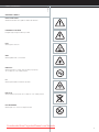
WARNING SYMBOLS
READ USER GUIDE
Attention! Read the user guide for further information!
DANGEROUS VOLTAGE
Danger! High voltage inside the product!
HOT
Warning! Hot surfaces!
WAIT
Warning! Wait until cooled down!
MERCURY
Warning! Product contains mercury! Recycle properly,
do not dispose of in ordinary waste!
UV
Warning! UV radiation inside the product!
RECYCLE
Warning! Recycle properly, do not dispose of in ordinary waste!
NO TELEPHONE
Warning! Do not connect to telephone lines!
Downloaded from ProjectorsManual.com Manuals

7
english
D
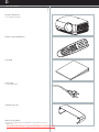
SUPPLIED MATERIAL
Projector without lens
Lens supplied seperately
Remote control with batteries
User guide
Power Cord
(country dependent)
Ceiling mount cover
Before Set up and Use
Unpack the supplied parts and familiarise yourself with the various
components.
Downloaded from ProjectorsManual.com Manuals

8
english
E
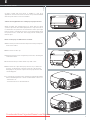
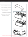
OPTIONAL LENSES
A range of fixed and zoom lenses is available to cover most
applications, both front and rear. The lenses are powered and fitted
with a bayonet mount for ease of installation.
Switch off all equipment before setting-up for proper function.
When mounting and changing lenses, be aware that the optical
system is exposed to dust and foreign particles as long as the lens is
not attached to the system. Do not leave the lens mount open longer
than necessary to change lens. If a lens is not mounted, always insert
the protection lid to avoid dust and foreign particles entering the
internal optics.
Never run the projector without lens mounted.
ARemove the protection lid from the bayonet mount by turning the
knob anti-clockwise.
BRemove the rear lens cap.
CAttach the projection lens using the bayonet mount, observing the
red insertion marks.
DTurn the lens firmly clockwise until it stops with a click.
ERemove the lens cap from the projection lens. If you switch the
projector on with the lens cap in place, the lens cap may melt,
damaging not only the lens cap, but also the projection lens and
surrounding parts.
FTo change lens, first remove the curret lens by pushing the release
button and twisting the lens counter-clockwise until it comes loose.
- Pull the lens out.
- Insert the new lens as described above.
A
B
D
C
E
F
Downloaded from ProjectorsManual.com Manuals


10
english
G
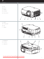
KEYPAD
The keypad is illuminated for operation in dark environments. Available
functions are illuminated in yellow while selected (active) functions are
illuminated in green. Functions that are not available are not illuminated.
In addition to the various functions, 10 keys are numbered 0-9. These
keys are used for PIN code and other numeric functions as applicable.
POWER
Switches the projector between on and standby modes. Press firmly
(1 sec) to switch on. Press firmly (1 sec) twice to switch off.
AUTO
Adjusting the projector to display a correct image, including position,
width, height, contrast, brightness and overall stability.
MENU
Activates the menu system. Use the four arrow keys to navigate and
«OK» to activate.
ARROW KEYS
Use the arrow keys to navigate the menu system or to control lens and
LCD functions.
OK
Confirm menu option when menu system is activated.
ZOOM
Select ZOOM, then use arrow keys to zoom in or out.
FOCUS
Select FOCUS, then arrow keys to focus the image
SHIFT
Select SHIFT, then the arrow keys to shift the image up, down or
sideways.
IRIS
Select IRIS, then arrow keys to adjust to desired combination of
brightness and contrast.
SHUTTER
Press SHUTTER to stop the projected image completely.
VGA
Selects the VGA input as active source.
DVI
Activates the DVI-D input.
BNC
Selects BNC as source.
YPbPr
Activates the component video input.
S-VIDEO
Selects super video as active source.
C-VIDEO
Activates the composite video input.
X-PORT 1
Activates the X-PORT 1. This key is enabled by the X-PORT 1 device
as and when attached. Functionality depends on the actual device
connected (see separate user guide for this device).
X-PORT 2
Activates the X-PORT 2. This key is enabled by the X-PORT 2 device
as and when attached. Functionality depends on the actual device
connected (see separate user guide for this device).
LIGHT
This key switches the illumination of the connector area on and off.
INDICATORS
The LAMP 1, LAMP 2 and STATUS indicators are not keys, so please
do not push.
english
Downloaded from ProjectorsManual.com Manuals

11
english
H
INDICATORS
STATUS
Indicates the overall system status by green, yellow and red colors.
PERMANENT GREEN LIGHT
The projector is turned on and in normal operation.
PERMANENT YELLOW LIGHT
The unit is in standby mode; no source(s) connected, or the source(s)
connected are inactive or switched off, thereby activating the power-
save function (DPMS). You may enable or disable the power save
function in the SET UP sub menu, DPMS on or off.
FLASHING YELLOW LIGHT
Please wait. The yellow light will flash a period after power cord is
connected (10-15 sec.), and a period after going to standby mode
while lamp is cooling down (approximately 45 sec.). The projector
may not be turned on again until the light has turned to permanent
yellow.
FLASHING RED LIGHT
Projector is overheated. Turn off immediately! Check if air inlets are
covered or if ambient temperature is outside specifications. The
projector can not be restarted unless the power cord is disconnected
and reconnected again. If the projector continues to flash red, you will
need to return the unit for service.
LAMP 1, LAMP 2
Indicate the status of each lamp by green and red colors.
PERMANENT GREEN LIGHT
The lamp is on and in normal operation.
PERMANENT YELLOW
The lamp is ready and in standby mode
PERMANENT RED LIGHT
Lamp life has expired. Please change projection lamp immediately.
Failing to change lamp may lead to lamp explosion.
NO LIGHT
No lamp inserted / connected
LCD
The projector is fitted with a backlit LCD screen that reports system
status. You can navigate the LCD screen by using the arrow keys on
the keypad.
Downloaded from ProjectorsManual.com Manuals

english
12
I
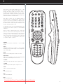
REMOTE CONTROL
The remote control allows flexible access to the
projector settings, either through direct keys, or
through the menu system. The remote control is
backlit for use in dark environments. It also has a data-
jack that allows for wired connection to the projector.
When the wire is connected, the IR (infra-red) beam
and internal batteries are switched off.
The remote control can be operated either in
'broadcast mode', or 'individual mode'. When several
projectors are in use in an installation, individual control
may be convenient. Individual control is available either
by wired remote control, using the data-jack, or by
using an individual number code.
For individual control, first set the individual RC ID code
using the projector menu system, see the UTILITIES
sub menu.
Then, to select a specific projector to control, first
press the '*' button in the lower keypad area, then the
code as set in the target projector. A code can be in
the range '0'..'255'. '0' is reserved for broadcast. To
select another target, repeat the process by pressing
'*' and a new code. To exit individual control, press
'*''*' twice or press '*' and '0'.
POWER
Switches the projector between on and standby
modes.
AUTO
Adjusting the projector to display a correct image,
including position, width, height, contrast, brightness
and overall stability.
INFO
Displays source and projector status on screen.
BACKLIGHT
Switches the backlight on and off. The backlight will
switch off automatically after ten seconds.
C-VIDEO
Selects the composite video input as signal source.
S-VIDEO
Selects the super video input as signal source.
YPbPr
Selects component video input.
DVI
Selects the DVI input.
VGA
Selects the VGA input.
BNC
Selects the BNC input.
Downloaded from ProjectorsManual.com Manuals

english
13
REMOTE CONTROL
X-PORT 1, 2
Activates the X-PORT 1, 2. These keys are enabled by
the X-PORT 1, 2 devices as and when attached.
Functionality depends on the actual devices connected
SHUTTER
Toggles the mechanical shutter on and off.
ZOOM
Press the ZOOM keys to zoom the image in and out.
FOCUS
Press the FOCUS keys to focus the image.
SHIFT
Press SHIFT, then the arrow keys to shift the image up,
down or sideways.
IRIS
Press the IRIS keys to adjust the optomechanical stop
to the desired combination of brightness and contrast.
BRIGHT
Press BRIGHTNESS, then the arrow keys to adjust
image brightness from dark to bright.
CONTRAST
Press CONTRAST, then the arrow keys to adjust the
image contrast from soft to hard.
ASPECT
Cycles through the aspect ratios available with the
current source.
MENU
Toggles the menu system on and off.
ARROW KEYS
Use the arrow keys to navigate in the menu system
and other adjustments.
LASER
Activates the built-in laser pointer. CAUTION! Do not
point laser beam at people. Do not stare into laser
beam.
OK
Press OK to confirm selected option in menu.
GAMMA
Press GM+ or GM- to select between gamma settings.
STORE
Press STORE, then one digit 0-9, to store user setting
in memory.
RECALL
Press RECALL, then one digit 0-9, to recall user
setting from memory.
0-9
Used for various numeric functions.
Downloaded from ProjectorsManual.com Manuals

14
J
english
CE
BFG
N
AHI
DL
N
M
JK
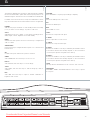
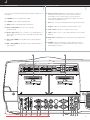
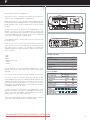
CONNECTOR PANEL
The conector panel may be illuminated by pushing the LIGHT key on
the keypad.
A C-VIDEO: Used for standard video quality.
B S-VIDEO: Used for improved quality video.
C YPbPr: Used for high quality video reproduction.
D DVI-D - Digital RGB: For a low noise computer
and video image.
E Monitor VGA out: Allows for connection to local VGA monitor or
daisy-chaining of several projectors using VGA. Works with VGA
inputs only.
F VGA - Analog RGB: The standard analog computer graphics
interface.
G BNC - Analog RGB: An alternative analog computer graphics or
video interface.
CONNECTOR PANEL
H RS 232 control in-out: Allows for wired remote control and
monitoring of many projector functions used in installation
environments. The secondary output connector allows for
daisy-chaining, enabling both individual and global control and
monitoring of multiple projectors.
I RC: Allows connection of external IR receiver or wired remote control.
J Triggers: 12VDC for Screen Drop and Aspect Ratio control
K USB - interface: Allows for computer mouse control.
L LAN: Provides access to control and monitoring over a Local Area
Network
M Mains power connector: Use only three-prong / grounded power
cord.
N X-PORT 1, 2: Custom interfaces used for application-specific
signal processing. Use only approved interfaces that conform to
the X-PORT specification.
english
Downloaded from ProjectorsManual.com Manuals

english
15
K
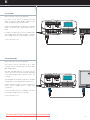
SET UP
SET UP VIDEO
Before setting-up, switch off all equipment.
Four video sources may be connected, using the
YPbPr (component), BNC (RGB), S-VIDEO (super
video) and VIDEO (composite video) inputs.
Component and RGB video will display more detailed
images. Composite video yields images with less
detail.
In addition, the DVI-D input can be used with video
sources (DVD player fitted with an HDCPTM compliant
DVI or HDMI connector) for a pure digital connection.
Connect the power cord.
SETUP COMPUTER
Before setting-up, switch off all equipment.
The projector may be connected to up to three
computer sources simultaneously, using the VGA,
BNC and DVI inputs.
The VGA and BNC interfaces are analog and may
cause some noise in the projected image, depending
on the signal quality from the graphics card in the
computer.
The DVI (Digital Visual Interface) interface is all-digital
and will yield a projected image with very low noise.
Connect the RS232 interface to allow for individual or
global control of multiple units in a daisy chain
configuration.
Connect the LAN connector for individual control and
monitoring of multiple projectors over LAN.
Connect the power cord.
Downloaded from ProjectorsManual.com Manuals

english
16
L
IMAGE ADJUSTMENTS
Various optical adjustments are available, depending
on your choice of lens. All lens adjustments are
motorized and controlled by the keypad, remote
control or by RS232 or LAN.
Two kinds of lenses are available; fixed or zoom. A
fixed lens has permanent focal length, or throw ratio. A
zoom lens has variable focal length or throw ratio.
In addition, fixed lenses may or may not be shiftable,
depending on type and model. See the specifications
for the particular lens.
The throw ratio is defined as the ratio between the
projection distance to the screen and the projected
image width. With a fixed lens, this ratio is set. With a
zoom lens, this ratio can be changed within certain
limits specific to the lens in use.
On the keypad, first select lens function, then use the
cursor keys to adjust. On the remote control, zoom
and focus are direct keys, while lens shift is operated
by first selecting SHIFT, then use the arrow keys.
A mechanical SHUTTER is employed that totally shuts
off the optical image path. The shutter is directly
available from the keypad and the remote control. The
shutter is also in place when there is no lens attached.
Select a lens suitable for the application. A range of
lenses from very wide to super telezoom is available.
Adjust the horizontal and vertical SHIFT, if applicable,
in order to align the image on screen.
If a zoom lens is used, adjust the image to the right
size. If a fixed lens is used, relocate the unit to achieve
the right image size.
FOCUS the image properly.
Adjust the IRIS to achieve the desired optical balance
between brightness and contrast. In a bright
environment, brightness is usually maximized resulting
in reduced contrast. In a dark environment, less light is
needed and desired, while high contrast and deep
blacks are appreciated.
To level the image, adjust the feet as needed by turning
the feet accordingly.
Downloaded from ProjectorsManual.com Manuals

17
english
M
LAMP OPERATION
The projector is fitted with two individual projection lamps that can be
run in various modes. In addition, lamps can be replaced as needed
separately. This ensures an optimized cost of ownership. Individual
lamp timers are maintained for each lamp.
Lamp operation mode is controlled in the LAMPS sub menu.
PIN CODE
The projector may be controlled by a PIN (Personal Identity Number)
code. The PIN code is 4 digits, and if the PIN code is activated, you
must issue the right code to unlock the projector.
To activate the PIN code, see the UTILITIES sub menu.
If a wrong PIN code is issued, you may try again two times. If you fail
three times in a row, a PUK (unnlock) code is needed. The PUK code
is supplied with the product.
If you also fail three times with the PUK code, the projector locks up
permanently, and can only be unlocked by a special service unlock
code.
To access this code, you will need to contact your dealer or a service
station. The service unlock code will be generated based on a secure,
encrypted number that is produced by the projector itself. The
projector will produce a new number every time.
english
N
Downloaded from ProjectorsManual.com Manuals

english
18
O
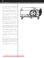
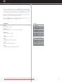
CEILING MOUNT
The projector can be ceiling mounted using an
approved UL tested/ listed ceiling mount fixture, with a
capacity of minimum 60 kg / 130 lbs.
For ceiling mount use M6 screws that penetrate
maximum 15 mm / 0.6” into the projector body.
For proper ventilation the minimum distance from
ceiling/ rear wall should be: 30/ 50 cm, 12/ 20 inch.
Ceiling Mount Interface
M6 Threads
384,9
111,8
94,3
15,5
95
82,5
59,5
53
123,1
163,3
300mm
500mm
Downloaded from ProjectorsManual.com Manuals

english
19
CEILING MOUNT
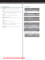
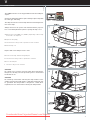
CEILING MOUNT COVER
The auxiliary cable cover can be mounted on the
projector to conceal the interface cables and power
cord when the unit is ceiling mounted.
Connect all cables and fix them in place before the
cable cover is attached to the projector.
A Attach the cable cover to the projector by inserting
the horisontal hooks on the cover in the horisontal
slots on the rear of the projector.
B Turn the cover untill the vertical hooks on the
cover are inserted into the vertical slots on the rear
of the projector.
C The cover will snap in place, to release pull the
vertical hooks on the cover out of the slots, letting
the cover hinge on the horisontal hooks.
B
C
A
Downloaded from ProjectorsManual.com Manuals

20
english
P
USING THE PROJECTOR
After setting-up, switch on all equipment.
The projector can be controlled by the keypad on the rear, by the
remote control or using the RS232 or LAN interfaces.
When using the remote control, either all or select individual units may
be addressed, see the CONTROL sub menu - RC ID. By activating the
RC ID, individual control of units in a multiple-unit set-up is then made
possible.
To switch the projector on, firmly press the POWER button on the
keypad or the remote control. The STATUS indicator will turn from
yellow to green when the unit is switched on. The keypad will light up
so that all available functions are yellow. Functions not available will
have no light. Selected functions will turn green.
If the STATUS indicator is flashing yellow, please wait until it turns
permanent yellow.
When only one source is connected, the projector will auto-detect that
source. If more sources are connected, the projector will search for the
next active source according to the following list, provided that
SOURCE SCAN is set to ON in the SET UP sub menu (see description
of menu system):
- VGA
- BNC
- DVI-D
- YPbPr (Component)
- S-Video
- C-Video
Select between the sources by pressing the SOURCE buttons on the
keypad or the remote control. Only sources that are active will be
displayed.
If no source is active, searching messages will appear on the screen.
If no source is active for a long time, the projector will go in standby
mode if DPMS (power save) is set to ON in the SET UP sub menu. The
STATUS indicator will turn from green to flashing yellow, then yellow.
The projector will be switched back on if at least one source is
(re)activated. The power-down function can be disabled in the menu.
See DPMS in the SET UP sub menu.
To switch the projector off, firmly press the POWER button on the
keypad or the remote control twice (to confirm that you really want to
switch off the unit). The STATUS indicator will turn from green to
flashing yellow, then yellow when switched off.
You may not switch the unit on while the STATUS indicator is flashing
yellow. Please wait until the indicator is permanent yellow.
mode RS232
RS232 Address auto fixed
RS232 Fixed 1
baudrate 19200
RC ID 0
keystone V 0
keystone H 0
IR control press
DPMS on off
source scan on off
orientation desktop front
OSD
language
RGB Video off
CONTROL SUB MENU
SET UP SUB MENU
Downloaded from ProjectorsManual.com Manuals

21
english
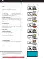
Q
MENU SYSTEM
The menu system gives access to a multitude of image and system
controls. The menu system is structured through a top menu and
several sub menus. The sub menus may vary depending on the actual
source selected. Some functions are not available with some sources.
When accessing the menu system, you will enter at the position you
left last time you were using the menu system.
Press the MENU key and navigate using the arrow keys on the
keypad or the arrow keys on the remote control
TOP MENU
picture
Basic picture controls.
dynamic
Allows additional control over the projected image.
advanced
Advanced picture controls.
set up
General projector controls.
utilities
System controls and information.
control
RS232 and LAN configurations.
lamps
Configuring single and dual lamp modes.
picture
dynamic
advanced
setup
utilities
control
lamps
setup
utilities
control
lamps
FOR ALL
NO SOURCE SELECTED
Downloaded from ProjectorsManual.com Manuals
Page is loading ...
Page is loading ...
Page is loading ...
Page is loading ...
Page is loading ...
Page is loading ...
Page is loading ...
Page is loading ...
Page is loading ...
Page is loading ...
Page is loading ...
Page is loading ...
Page is loading ...
Page is loading ...
Page is loading ...
Page is loading ...
-
 1
1
-
 2
2
-
 3
3
-
 4
4
-
 5
5
-
 6
6
-
 7
7
-
 8
8
-
 9
9
-
 10
10
-
 11
11
-
 12
12
-
 13
13
-
 14
14
-
 15
15
-
 16
16
-
 17
17
-
 18
18
-
 19
19
-
 20
20
-
 21
21
-
 22
22
-
 23
23
-
 24
24
-
 25
25
-
 26
26
-
 27
27
-
 28
28
-
 29
29
-
 30
30
-
 31
31
-
 32
32
-
 33
33
-
 34
34
-
 35
35
-
 36
36


Projectiondesign F22 User manual
- Category
- Data projectors
- Type
- User manual
Ask a question and I''ll find the answer in the document
Finding information in a document is now easier with AI
Related papers
Other documents
-
BenQ W10000/W9000 User manual
-
Mitsubishi Electric hc3000u User manual
-
Sanyo PLC-XP57L Owner's manual
-
Panasonic PT-AE700U User manual
-
Hitachi CP-WUX645N Operating instructions
-
-
-
-
Canon LV-7220 Owner's manual
-