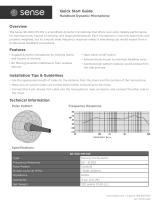
Superlux UT Series User guide

Category
Supplementary music equipment
Type
User guide
UT6 series
UHF wireless microphone system
User Manual
UT6_UM.indd 1 2009/5/7 �� 04:20:31
Contents
UT6_UM.indd 2 2009/5/7 �� 04:20:31
Page. 1
Contents
1. Preface: 2
2. Unpacking 2
3. Receiver Introduction 4
3.1 Front view 4
3.2 Rear view 4
4. Receiver Connections 6
5. Receiver Operation 8
6. Receiver Installation 9
7. Receiver LCD operation 11
7.1 LCD layout and buttons 11
7.2 Menu function 11
7.2.1 Locking and unlocking 11
7.2.2 G/CH: Display group and channel setting 12
7.2.3 FREQ: Display frequency in use 13
7.2.4 SQ: Squelch setting 14
7.2.5 VOL: Display volume on or mute 15
7.2.6 NAME: Displaying and naming receiver 16
7.3 FIC, Frequency Infrared Control 17
8. Receiver Cautions 18
9. Receiver Accessories 19
10. Handheld wireless microphone 20
10.1 Handheld wireless microphone Introduction 20
10.2 Inserting batteries 21
10.3 LCD 22
10.4 Color coded cover 23
11. Beltpack transmitter 24
11.1 Introduction 24
11.2 Operating 26
11.3 Wiring for audio input 27
11.4 LCD 28
11.5 Batteries exchange 29
12. Specification 30
13. Capsules for handheld microphone 32
14. Microphones for beltpack transmitter 33
15. Knowing your microphone 34
UT6_UM.indd 1 2009/5/7 �� 04:20:31
Page. 2
1. Preface
2. Unpacking
1 x dual plug cable
1 x power supply
1 x user manual
1 x warranty card
1 x UT6 receiver
2 x antenna (under UT6 receiver)
Optional headworn microphone
Optional UT2 beltpack transmitter
Optional UT4 handheld transmitter
Thank you for choosing the Superlux
UT6 series UHF wirelss microphone.
This remarkable component has been
engineered to provide superb sound
pick-up with stable transmission
and receiption, as well as providing
outstanding ease of operation.
As this product is provided with a wide
selections of microphones and connec-
tion possibilities, we recommend that
before you begin hookup and operation
that you review the contents of this
manual before proceeding.
Your package
There are combinations of products for various
demands. There are 2 type of transmitter in this UT6
system, handheld of beltpack. User can include both
in this package, but only one transmitter can operate at
the same time.
For handheld user, there are 4 types of capsules to
choose, 2 dynamics, 1 true condenser, and 1 electret
condenser.
For beltpack user, there are 7 microphones and 1 cable
to choose.
Your package can be any combination. Please verify the
contents with your dealer. Future upgrade with more
components can be easily made by contacting your
dealer.
UT6_UM.indd 2 2009/5/7 �� 04:20:31
Page. 3
UT6_UM.indd 3 2009/5/7 �� 04:20:34
Page. 4
single channel receiver
3. Receiver Introduction
Rear view
Rack mount side panel (optional)
Front panel antenna A socket: for optional
antenna extension from rear panel.
Front panel antenna B socket: for optional
antenna extension from rear panel.
Antenna B socket
Front view
Illustration 1
Illustration 2
UT6_UM.indd 4 2009/5/7 �� 04:20:34
Page. 5
Rack mount side panel, 1/2 space width (optional)
single channel receiver
Color LCD display panel
Power switch: LED indicator lighted when power-on.
Balanced audio output, XLR-3M, microphone level
Un-balanced audio level switch: Switch between “MIC” or “LINE” level for un-balanced output socket.
Un-balanced audio output socket: 6.3mm phone jack, level switchable
DC power socket: 12VDC power source, center positive.
Antenna A socket
single channel receiver
UT6_UM.indd 5 2009/5/7 �� 04:20:35
Page. 6
single channel receiver
4. Receiver Connections
4.1 Connect both antenna to rear panel socket and as illustration 3.
4.2 Connect power adapter output to receiver and plug into power line (Caution:
check power source specification, make sure the power adapter matches the
source spec.
4.3 Audio connections:
4.3.1 Level switch , when un-balanced output socket is connected to mixers or
amplifiers’ line level input, switch the output level to “LINE” position. When
connected to mixers or amplifiers’ mic level input, switch the output level
to “MIC” position. Mis-match level setting, will result distortion or high
noise. When used with guitar, keep the level at “LINE” position.
Illustration 3
single channel receiver
UT6_UM.indd 6 2009/5/7 �� 04:20:35
Page. 7
single channel receiver
4.3.2 Un-balanced connection: When receiver and mixer are positioned
at short distance, 6.3mm phone type plugs can be used with un-
balanced connection.
4.3.3 Balanced connection: When receiver is located at a remote loca-
tion from mixer, balanced XLR cable shall be used. Pin 2 hot at
receiver output.
4.3.4 When electric guitar is in used, connect PHONE output to guitar
amp input and level switch to “LINE”.
Ground
Signal +
Signal
-
Illustration 4
UT6_UM.indd 7 2009/5/7 �� 04:20:35
Page. 8
single channel receiver
5. Receiver Operation
5.1 Set mixer/amplifier input level to minimum or mute the channel. Turn on the
receiver, the indicator shall be lighted to show the operation status.
5.2 Power up the matched channel transmitter, the RF level indication shall be
lighted.
5.3 Adjust the mixer/amplifier level to optimum and test the microphone/transmit-
ter with normal talking or instrument playing. The AF level indicators shall show
the AF signal.
Notes:
If audio signal doesn’t show or go through the mixer/amplifier, check the signal
chain, connections, level settings...
Wireless microphone level controlled only on mixer/amplfier, the only setting of the
receiver is “MIC/LINE” position.
single channel receiver
UT6_UM.indd 8 2009/5/7 �� 04:20:35
Page. 9
single channel receiver
6. Receiver Installation
6.1 Single receiver half width space rack mouting
6.1.1 Mount the rack mouting kit with receiver according to illustration 5.
6.2 Dual receivers, full width space rack mouting
6.2.1 Unscrew the 4 screws according to the illustration 6.
6.2.2 Mount the connection plate with previous 4 screws to interlock the 2
receivers.
6.2.3 Mount the rack brackets to both ends as illustration.
Illustration 5
Illustration 6
UT6_UM.indd 9 2009/5/7 �� 04:20:35
Page. 10
single channel receiver
6.3 After the rack mount kit was properly installed, the receiver(s) can be mounted
into EIA standard rack for 1 space height, as illustrated.
6.4 For best receiption, receiver shall be located at least 1 meter above ground.
Transmitter shall be at least 1 meter away and keep away from noise as illustra-
tion.
Illustration 7
Illustration 8
>1M
>1M
>1M
>1M
single channel receiver
UT6_UM.indd 10 2009/5/7 �� 04:20:35
Page. 11
single channel receiver
7.1 LCD layout and buttons
7. LCD operation
7.2 Menu Function
Menu: To access function menu
By pressing this button, user can go through selections of function:
NAME G/CH FREQ
SQ VOL
7.2.1: Locking and unlocking
a. To lock in order to prevent mis-operating, press MENU and hold for more than
3 seconds until LCD shows “LOCK”. At this time, all buttons except “FIC” will
be disable. Receiver operation are now locked.
b. To unlock, press MENU and hold for more than 3 seconds until LCD shows
“UNLOCK”. Receiver are now unlocked.
UT6_UM.indd 11 2009/5/7 �� 04:20:35
Page. 12
MENU
G/CH
GROUP
MENU
A: GROUP setting steps:
B: Group setting detail:
a. Press MENU key, select G/CH, LCD displaying 2 double digit number as GROUP and
CHANNEL connected with a dash line.
b. Press GROUP key once, GROUP double digit flashes indicating ready for setting.
Pressing again, GROUP number will cycle through all selections and CHANNEL
number will show the first in the GROUP. Pressing and hold GROUP will keep cy-
cling until release. To stop digits flashing and confirm GROUP setting, simply press
MENU or SCAN .
single channel receiver
save
&
exit
7.2.2 G/CH: Displaying group and channel setting and changing.
single channel receiver
UT6_UM.indd 12 2009/5/7 �� 04:20:36
Page. 13
single channel receiver
7.2.3 FREQ: Displaying frequency in use
single channel receiver
MENU
G/CH
SCAN
MENU
save
&
exit
D: Channel setting
a. Press MENU to select G/CH functon. Press SCAN key once, CHANNEL double
digit flashes indicating ready for setting.
b. Pressing SCAN again, receiver start to scan channels and stop at the first avail-
able channel. If all channels in the group are taken and the receiver keep on scan-
ning, user shall go the another group. Pressing SCAN once or holding, receiver will
keep on scanning until SCAN key released. To stop double digit flashing and confirm
channel setting, press MENU again to complete.
C: CHANNEL setting steps:
A, Steps:
B, Operations:
a. Press MENU to select FREQ.
b. This function only display frequency, and user cannot change the frequency.
MENU
FREQ
UT6_UM.indd 13 2009/5/7 �� 04:20:36
Page. 14
single channel receiver
7.2.4 SQ: Squelch setting and change
A: SQ setting steps:
MENU
SQ
01 ↑↓
MENU
save
&
exit
B: SQ setting detail
a. SQuelch range from 01 to 99.
b. Pressing UP or DOWN to change value.
c. Press MENU to confirm store and exit.
d. The higher value, the lower receiption sensitivity.
UP
DOWN
single channel receiver
UT6_UM.indd 14 2009/5/7 �� 04:20:36
Page. 15
single channel receiver
7.2.5 VOL: Display Volume ON or MUTE.
A: VOL setting steps:
MENU
VOL
MUTE ↑↓
MENU
save
&
exit
B: VOL setting detail
a. Pressing UP or DOWN to change from ON to MUTE and cycling.
b. Press MENU to confirm store and exit.
C: Cautions
a. When receiver in muted, AF, ANT A, ANT B level bars will not display.
b. To varify if the receiver is muted, press MENU until VOL selected.
c. If MUTE is displayed, indicating receiver is muted. If ON is displayed, indicating
receiver sending AF signal.
UP
DOWN
UT6_UM.indd 15 2009/5/7 �� 04:20:36
Page. 16
A: NAME setting steps:
MENU
NAME
A ↑↓
MENU
save
&
exit
B: NAME setting detail
a. NAME up to 6 characters, alphabets upper case, numbers, +, -, *, /, and space.
b. Pressing UP or DOWN to edit the flashing digit.
c. Once the desired character is shown, press MENU to accept and go to the next digit.
d. Repeat step b to c until all 6 digits are set, press MENU will save the NAME and exit.
UP
DOWN
single channel receiver
A_ ↑↓
MENU
UP
DOWN
7.2.6 NAME: Displaying and naming receiver
single channel receiver
UT6_UM.indd 16 2009/5/7 �� 04:20:36
Page. 17
single channel receiver
A: FIC setting steps:
FIC
FIC
exit
B: FIC setting detail
a. When the function is set at G/CH mode, press FIC key momentaryly will activating
FIC operation and LCD will display “FIC”.
b. Put microphone with FIC window facing receiver within 30 cm as illustration.
c. As soon as microphone channel was sync with receiver, FIC operation completed
and LCD resume.
d. When FIC operation is activated, if no microphone channel was sync with receiver
within 10 seconds, FIC operation will abort.
7.3 FIC function, Frequency IR Control
Illustration 9
UT6_UM.indd 17 2009/5/7 �� 04:20:36
Page. 18
single channel receiver
8, Receiver Cautions
8.1 DC supplier shall be no less than 12VDC to operate normally, and shall not exceed
15VDC in order not to damage the receiver. Power capacity shall be at least 1A and
regulated.
8.2 Please use supplied antenna to ensure receiption performance.
8.3 Antenna socket provide 8VDC output, please do not short circuit.
RK1
RK2
RK1 Rack mount kit, for sigle receiver
mounting onto standard 19” width
rack.
RK2 Rack mount kit, for dual receivers
mounting onto standard 19” width
rack.
Receiver Accessories
UT6_UM.indd 18 2009/5/7 �� 04:20:40
  • Page 1 1
  • Page 2 2
  • Page 3 3
  • Page 4 4
  • Page 5 5
  • Page 6 6
  • Page 7 7
  • Page 8 8
  • Page 9 9
  • Page 10 10
  • Page 11 11
  • Page 12 12
  • Page 13 13
  • Page 14 14
  • Page 15 15
  • Page 16 16
  • Page 17 17
  • Page 18 18
  • Page 19 19
  • Page 20 20
  • Page 21 21
  • Page 22 22
  • Page 23 23
  • Page 24 24
  • Page 25 25
  • Page 26 26
  • Page 27 27
  • Page 28 28
  • Page 29 29
  • Page 30 30
  • Page 31 31
  • Page 32 32
  • Page 33 33
  • Page 34 34
  • Page 35 35
  • Page 36 36
  • Page 37 37
  • Page 38 38
  • Page 39 39
  • Page 40 40

Superlux UT Series User guide

Category
Supplementary music equipment
Type
User guide

Ask a question and I''ll find the answer in the document

Finding information in a document is now easier with AI