EN
2
This kit is ul approved to allow certain microwave ovens to
be installed above any electric wall oven. Please see the use
& care manual regarding approved built-in applications.
IMPORTANT This Trim Kit is designed for and approved
only for Fulgor Milano Microwave Oven specifying Trim
Kit F4TK30MWO.
PLEASE READ THESE INSTRUCTIONS THOROUGHLY
BEFORE BEGINNING INSTALLATION!
• Be sure to DISCONNECT THE PLUG of the microwave
oven from the electrical outlet before installing the Trim
Kit. Remove the turntable from the oven cavity.
• Because the kit includes metal parts, due caution should
be used in handling and installation to avoid the pos-
sibility of injury.
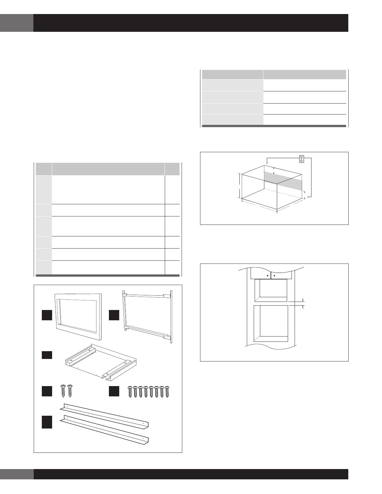
ITEM PART NAMES QTY
A
Front Frame: FDECAB265MRK0
W x H x D: 29
7
⁄8” x 18
1
⁄2” x 1
3
⁄16”
(759 x 470 x 30.2 mm)
1
B
Back Frame: FDECAB266MRK0 1
C
Exhaust Duct Assembly:
PDUC-B185MRP0A
1
D
Screw D: XTSS740P20000 2
E
Screw E: XOPS740P16000 8
F
Air Deflector: PREF-B035MRP0 2
A B
D
F
C
E
STEP 1 - CABINET OR WALL OPENING
The opening in the wall or cabinet must be within the
following dimensions:
CUT OUT DIMENSIONS
A (Height)
17” (432 mm)
B (Width)
25
1
⁄4” (641 mm)
C (Minimum Depth)
20” (508 mm)
D
4” (101.6 mm)
Outlet should NOT be in the shaded area as indicated on
Sketch 1.
A
B
D
C
D
Sketch 1
NOTES
• Please allow minimum 3" (76 mm) wood gap between
the microwave oven cutout and the appliance cutout
below the microwave oven. See Sketch 2.
3"
Min.
Microwave cutout
Wall oven cutout
Sketch 2
• If the dimension of DEPTH (C) is more than 21" (533.4
mm), the outlet location may be any area on the rear wall.
• The floor of the opening should be constructed of
plywood strong enough to support the weight of the oven
and floor load (about 100 pounds/45 KG). The floor
should be level and 90˚ with the face of the cabinet for
proper installation and operation of the oven. Be sure
to check the local building code as it may require that
the opening be enclosed with sides, ceiling and rear
partition. The proper functioning of the oven does not
require the enclosure.
Standard Installation Guide


