MSI 880GM-E41 Owner's manual
- Category
- Motherboards
- Type
- Owner's manual
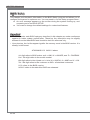
This manual is also suitable for

880GM-E41 series
MS-7623 (v2.x) Mainboard
G52-76231XC

ii
Preface
MS-7623
Preface
Preface
MS-7623
Preface
Copyright Notice
The material in this document is the intellectual property of MICRO-STAR INTERNA-
TIONAL. We take every care in the preparation of this document, but no guarantee is
given as to the correctness of its contents. Our products are under continual improve-
ment and we reserve the right to make changes without notice.
Trademarks
All trademarks are the properties of their respective owners.
MSI
®
is registered trademark of Micro-Star Int’l Co.,Ltd.
NVIDIA
®
is registered trademark of NVIDIA Corporation.
ATI
®
is registered trademark of ATI Technologies, Inc.
AMD
®
is registered trademarks of AMD Corporation.
Intel
®
is registered trademarks of Intel Corporation.
Windows
®
is registered trademarks of Microsoft Corporation.
AMI
®
is registered trademark of American Megatrends, Inc.
Award
®
is a registered trademark of Phoenix Technologies Ltd.
Sound Blaster
®
is registered trademark of Creative Technology Ltd.
Realtek
®
is registered trademark of Realtek Semiconductor Corporation.
JMicron
®
is registered trademark of JMicron Technology Corporation.
Netware
®
is a registered trademark of Novell, Inc.
Revision History
Revision Revision History Date
V2.0 First release. For 760GM-P31/ 760GM-P35/
785GM-P35/ 785GM-P45 Europe
December 2009
V2.1 For 880GM-E41 Europe May 2010
Technical Support
If a problem arises with your system and no solution can be obtained from the user’s
manual, please contact your place of purchase or local distributor. Alternatively, please
try the following help resources for further guidance.
Visit the MSI website for FAQ, technical guide, BIOS updates, driver updates,
and other information:
http://www.msi.com/index.php?func=service
Contact our technical sta at:
http://ocss.msi.com
■
■
■
■
■
■
■
■
■
■
■
■
◙
◙

Preface
MS-7623
Preface
iii
Preface
MS-7623
Preface
Safety Instructions
Always read the safety instructions carefully.
Keep this User’s Manual for future reference.
Keep this equipment away from humidity.
Lay this equipment on a reliable at surface before setting it up.
The openings on the enclosure are for air convection hence protects the equipment
from overheating. DO NOT COVER THE OPENINGS.
Make sure the voltage of the power source and adjust properly 110/220V before
connecting the equipment to the power inlet.
Place the power cord such a way that people can not step on it. Do not place any-
thing over the power cord.
Always Unplug the Power Cord before inserting any add-on card or module.
All cautions and warnings on the equipment should be noted.
Never pour any liquid into the opening that could damage or cause electrical
shock.
If any of the following situations arises, get the equipment checked by service
personnel:
The power cord or plug is damaged.
Liquid has penetrated into the equipment.
The equipment has been exposed to moisture.
The equipment does not work well or you can not get it work according to User’s
Manual.
The equipment has dropped and damaged.
The equipment has obvious sign of breakage.
DO NOT LEAVE THIS EQUIPMENT IN AN ENVIRONMENT UNCONDITIONED,
STORAGE TEMPERATURE ABOVE 60
o
C (140
o
F), IT MAY DAMAGE THE EQUIP-
MENT.
CAUTION: Danger of explosion if battery is incorrectly replaced.
Replace only with the same or equivalent type recommended by the manufacturer.
警告使用者:
這是甲類資訊產品,在居住的環境中使用時,可能會造成無線電干擾,在這種情況下,
使用者會被要求採取某些適當的對策。
廢電池請回收
For better environmental protection, waste batteries should be
collected separately for recycling special disposal.
■
■
■
■
■
■
■
■
■
■
■
◯
◯
◯
◯
◯
◯

iv
Preface
MS-7623
Preface
Preface
MS-7623
Preface
FCC-B Radio Frequency Interference Statement
This equipment has been tested and found
to comply with the limits for a Class B digi-
tal device, pursuant to Part 15 of the FCC
Rules. These limits are designed to provide
reasonable protection against harmful inter-
ference in a residential installation. This equipment generates, uses and can radiate
radio frequency energy and, if not installed and used in accordance with the instruc-
tions, may cause harmful interference to radio communications. However, there is no
guarantee that interference will not occur in a particular installation. If this equipment
does cause harmful interference to radio or television reception, which can be deter-
mined by turning the equipment o and on, the user is encouraged to try to correct the
interference by one or more of the measures listed below.
Reorient or relocate the receiving antenna.
Increase the separation between the equipment and receiver.
Connect the equipment into an outlet on a circuit dierent from that to which the
receiver is connected.
Consult the dealer or an experienced radio/television technician for help.
Notice 1
The changes or modications not expressly approved by the party responsible for com-
pliance could void the user’s authority to operate the equipment.
Notice 2
Shielded interface cables and A.C. power cord, if any, must be used in order to comply
with the emission limits.
VOIR LA NOTICE D’INSTALLATION AVANT DE RACCORDER AU RESEAU.
◯
◯
◯
◯
This device complies with Part 15 of the FCC Rules. Operation is subject to the follow-
ing two conditions:
this device may not cause harmful interference, and
this device must accept any interference received, including interference that may
cause undesired operation.
1)
2)
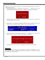
Micro-Star International
MS-7623
Page is loading ...

vi
Preface
MS-7623
Preface
Preface
MS-7623
Preface
ESPAÑOL
MSI como empresa comprometida con la protección del medio ambiente, recomienda:
Bajo la directiva 2002/96/EC de la Unión Europea en materia de desechos y/o equi-
pos electrónicos, con fecha de rigor desde el 13 de agosto de 2005, los productos
clasicados como “eléctricos y equipos electrónicos” no pueden ser depositados en
los contenedores habituales de su municipio, los fabricantes de equipos electrónicos,
están obligados a hacerse cargo de dichos productos al termino de su período de vida.
MSI estará comprometido con los términos de recogida de sus productos vendidos en
la Unión Europea al nal de su periodo de vida. Usted debe depositar estos productos
en el punto limpio establecido por el ayuntamiento de su localidad o entregar a una
empresa autorizada para la recogida de estos residuos.
NEDERLANDS
Om het milieu te beschermen, wil MSI u eraan herinneren dat….
De richtlijn van de Europese Unie (EU) met betrekking tot Vervuiling van Electrische
en Electronische producten (2002/96/EC), die op 13 Augustus 2005 in zal gaan kun-
nen niet meer beschouwd worden als vervuiling. Fabrikanten van dit soort producten
worden verplicht om producten retour te nemen aan het eind van hun levenscyclus.
MSI zal overeenkomstig de richtlijn handelen voor de producten die de merknaam MSI
dragen en verkocht zijn in de EU. Deze goederen kunnen geretourneerd worden op
lokale inzamelingspunten.
SRPSKI
Da bi zaštitili prirodnu sredinu, i kao preduzeće koje vodi računa o okolini i prirodnoj
sredini, MSI mora da vas podesti da…
Po Direktivi Evropske unije (“EU”) o odbačenoj ekektronskoj i električnoj opremi, Di-
rektiva 2002/96/EC, koja stupa na snagu od 13. Avgusta 2005, proizvodi koji spadaju
pod “elektronsku i električnu opremu” ne mogu više biti odbačeni kao običan otpad i
proizvođači ove opreme biće prinuđeni da uzmu natrag ove proizvode na kraju njihovog
uobičajenog veka trajanja. MSI će poštovati zahtev o preuzimanju ovakvih proizvoda
kojima je istekao vek trajanja, koji imaju MSI oznaku i koji su prodati u EU. Ove proiz-
vode možete vratiti na lokalnim mestima za prikupljanje.
POLSKI
Aby chronić nasze środowisko naturalne oraz jako rma dbająca o ekologię, MSI przy-
pomina, że...
Zgodnie z Dyrektywą Unii Europejskiej (“UE”) dotyczącą odpadów produktów elektry-
cznych i elektronicznych (Dyrektywa 2002/96/EC), która wchodzi w życie 13 sierpnia
2005, tzw. “produkty oraz wyposażenie elektryczne i elektroniczne “ nie mogą być trak-
towane jako śmieci komunalne, tak więc producenci tych produktów będą zobowiązani
do odbierania ich w momencie gdy produkt jest wycofywany z użycia. MSI wypełni
wymagania UE, przyjmując produkty (sprzedawane na terenie Unii Europejskiej) wy-
cofywane z użycia. Produkty MSI będzie można zwracać w wyznaczonych punktach
zbiorczych.

Preface
MS-7623
Preface
vii
Preface
MS-7623
Preface
TÜRKÇE
Çevreci özelliğiyle bilinen MSI dünyada çevreyi korumak için hatırlatır:
Avrupa Birliği (AB) Kararnamesi Elektrik ve Elektronik Malzeme Atığı, 2002/96/EC
Kararnamesi altında 13 Ağustos 2005 tarihinden itibaren geçerli olmak üzere, elektrikli
ve elektronik malzemeler diğer atıklar gibi çöpe atılamayacak ve bu elektonik cihazların
üreticileri, cihazların kullanım süreleri bittikten sonra ürünleri geri toplamakla yükümlü
olacaktır. Avrupa Birliği’ne satılan MSI markalı ürünlerin kullanım süreleri bittiğinde MSI
ürünlerin geri alınması isteği ile işbirliği içerisinde olacaktır. Ürünlerinizi yerel toplama
noktalarına bırakabilirsiniz.
ČESKY
Záleží nám na ochraně životního prostředí - společnost MSI upozorňuje...
Podle směrnice Evropské unie (“EU”) o likvidaci elektrických a elektronických výrobků
2002/96/EC platné od 13. srpna 2005 je zakázáno likvidovat “elektrické a elektronické
výrobky” v běžném komunálním odpadu a výrobci elektronických výrobků, na které se
tato směrnice vztahuje, budou povinni odebírat takové výrobky zpět po skončení je-
jich životnosti. Společnost MSI splní požadavky na odebírání výrobků značky MSI,
prodávaných v zemích EU, po skončení jejich životnosti. Tyto výrobky můžete odevzdat
v místních sběrnách.
MAGYAR
Annak érdekében, hogy környezetünket megvédjük, illetve környezetvédőként fellépve
az MSI emlékezteti Önt, hogy ...
Az Európai Unió („EU”) 2005. augusztus 13-án hatályba lépő, az elektromos és elek-
tronikus berendezések hulladékairól szóló 2002/96/EK irányelve szerint az elektromos
és elektronikus berendezések többé nem kezelhetőek lakossági hulladékként, és az
ilyen elektronikus berendezések gyártói kötelessé válnak az ilyen termékek visszavé-
telére azok hasznos élettartama végén. Az MSI betartja a termékvisszavétellel kapc-
solatos követelményeket az MSI márkanév alatt az EU-n belül értékesített termékek
esetében, azok élettartamának végén. Az ilyen termékeket a legközelebbi gyűjtőhelyre
viheti.
ITALIANO
Per proteggere l’ambiente, MSI, da sempre amica della natura, ti ricorda che….
In base alla Direttiva dell’Unione Europea (EU) sullo Smaltimento dei Materiali Elettrici
ed Elettronici, Direttiva 2002/96/EC in vigore dal 13 Agosto 2005, prodotti appartenenti
alla categoria dei Materiali Elettrici ed Elettronici non possono più essere eliminati come
riuti municipali: i produttori di detti materiali saranno obbligati a ritirare ogni prodotto
alla ne del suo ciclo di vita. MSI si adeguerà a tale Direttiva ritirando tutti i prodotti
marchiati MSI che sono stati venduti all’interno dell’Unione Europea alla ne del loro
ciclo di vita. È possibile portare i prodotti nel più vicino punto di raccolta

viii
Preface
MS-7623
Preface
Preface
MS-7623
Preface
Contents
Copyright Notice ............................................................................................ ii
Trademarks .................................................................................................... ii
Revision History............................................................................................. ii
Technical Support.......................................................................................... ii
Safety Instructions .........................................................................................iii
FCC-B Radio Frequency Interference Statement.......................................... iv
WEEE (Waste Electrical and Electronic Equipment) Statement .................... v
English ...................................................................................................... En-1
Mainboard Specications ...................................................................................En-2
Quick Components Guide ..................................................................................En-4
Screw Holes .......................................................................................................En-5
CPU (Central Processing Unit) ..........................................................................En-6
Memory ..............................................................................................................En-9
Power Supply ...................................................................................................En-11
Back Panel .......................................................................................................En-12
Connectors .......................................................................................................En-14
Switch ...............................................................................................................En-20
Jumpers ...........................................................................................................En-21
Slots .................................................................................................................En-22
LED Status Indicators ......................................................................................En-23
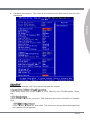
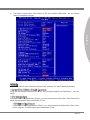
BIOS Setup ......................................................................................................En-24
Software Information ........................................................................................En-34
Deutsch .................................................................................................... De-1
Spezikationen .................................................................................................. De-2
Komponenten-Übersicht ................................................................................... De-4
Schraubenlöcher ............................................................................................... De-5
CPU (Prozessor) ............................................................................................... De-6
Speicher ............................................................................................................ De-9
Stromversorgung ............................................................................................. De-11
Rücktafel ......................................................................................................... De-12
Anschlüssen .................................................................................................... De-14
Schalter ........................................................................................................... De-20
Steckbrücke .................................................................................................... De-21
Steckplätze ...................................................................................................... De-22
LED Statusdikatoren ....................................................................................... De-23
BIOS Setup ..................................................................................................... De-24
Software-Information ....................................................................................... De-34
Page is loading ...


English
880GM-E41
Series
Europe version

En-2
MS-7623 Mainboard
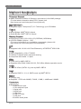
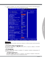
Mainboard Specications
Processor Support
AMD
®
Phenom II/ Athlon II/ Sempron processors in the AM3 package
(For the latest information about CPU, please visit
http://www.msi.com/index.php?func=cpuform2)
HyperTransport
Supports Hyper Transport(HT) 3.0 Technology up to 5200MHz
Chipset
North Bridge: AMD
®
880G chipset
South Bridge: AMD
®
SB710 chipset
Memory Support
DDR3 800/ 1066/ 1333/ 1600 (OC) SDRAM (16GB Max)
4 DDR3 DIMMs (240pin / 1.5V)
(For more information on compatible components, please visit
http://www.msi.com/index.php?func=testreport)
LAN
Supports LAN 10/100/1000 Fast Ethernet by ATHEROS
®
AR8131M
Audio
Chip integrated by VIA
®
VT1828S
Flexible 8-channel audio with jack sensing
Compliant with Azalia 1.0 Spec
IDE
1 IDE port by AMD
®
SB710
Supports Ultra DMA 33/66/100/133, PIO & Bus Master operation mode
SATA
6 SATA 3Gb/s (SATA1~6) ports by AMD
®
SB710
RAID
Supports RAID 0/ 1/ 0+1/ JBOD mode by AMD
®
SB710
Floppy
1 oppy port
Supports 1 FDD with 360KB, 720KB, 1.2MB, 1.44MB and 2.88MB
Connectors
Back panel
1 PS/2 mouse port
1 PS/2 keyboard port
1 Serial port
1 HDMI port
1 VGA port
4 USB 2.0 Ports
1 LAN jack
6 exible audio jacks
■
■
■
■
■
■
■
■
■
■
■
■
■
■
■
■
■
-
-
-
-
-
-
-
-

En-3
English
On-Board Connectors
3 USB 2.0 connectors
1 Serial port connector
1 CD-In connector
1 Front Panel Audio connector
1 SPDIF-Out connector
1 Chassis Intrusion connector
1 TPM connector
1 Parallel port connector
1 OC switch
Slots
1 PCI Express x16 slot
2 PCI Express x1 slots
1 PCI slot, support 3.3V/ 5V PCI bus Interface
Form Factor
Micro-ATX (24.4cm X 20.0 cm)
Mounting
6 mounting holes
(If you need to purchase accessories and request the part numbers, you could search
the product web page and nd details on our web address below
http://www.msi.com/index.php)
■
-
-
-
-
-
-
-
-
-
■
■
■
■
■

En-4
MS-7623 Mainboard
BA
TT
+
SO CK ET A M3
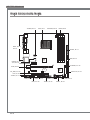
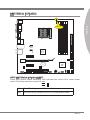
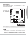
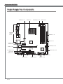
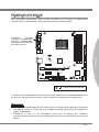
Quick Components Guide
CPU, En-6 DDR3, En-9
Back Panel,
En-12
JPWR1, En-11
JPWR2, En-11
FDD1, En-14
IDE1, En-14
SATA1~6, En-15
JFP1, JFP2, En-15
SYSFAN1, En-16
CPUFAN, En-16
JCI1, En-16
JCD1, En-16 JUSB1~3, En-17
JSP1, En-18
JAUD1, En-17
PCIE, En-22
PCI, En-22
JTPM1, En-18 JBAT1, En-21
JCOM1, En-19
OC_SW1, En-20

En-5
English
BA
TT
+
SO CK ET A M3
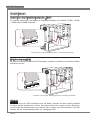
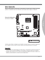
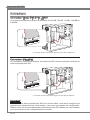
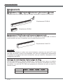
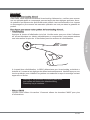
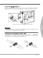
Screw Holes
When you install the mainboard, you have to place the mainboard into the chassis in the
correct direction. The locations of screws holes on the mainboard are shown as below.
Refer above picture to install standos in the appropriate locations on chassis and then
screw through the mainboard screw holes into the standos.
Important
To prevent damage to the mainboard, any contact between the mainboard circuit and
chassis or unnecessary standos mounted on the chassis is prohibited.
Please make sure there is no metal components placed on the mainboard or within
the chassis that may cause short circuit of the mainboard.
•
•
Screw holes
The side has to toward
the rear, the position
for the I/O shield of the
chassis.

En-6
MS-7623 Mainboard
CPU (Central Processing Unit)
When you are installing the CPU, make sure to install the cooler to prevent overheating.
If you do not have the CPU cooler, consult your dealer before turning on the computer.
For the latest information about CPU, please visit http://www.msi.com/index.
php?func=cpuform2
Important
Overheating
Overheating will seriously damage the CPU and system. Always make sure the cooling
fan can work properly to protect the CPU from overheating. Make sure that you apply
an even layer of thermal paste (or thermal tape) between the CPU and the heatsink to
enhance heat dissipation.
Replacing the CPU
While replacing the CPU, always turn o the ATX power supply or unplug the power
supply’s power cord from the grounded outlet rst to ensure the safety of CPU.
Overclocking
This mainboard is designed to support overclocking. However, please make sure your
components are able to tolerate such abnormal setting, while doing overclocking. Any
attempt to operate beyond product specications is not recommended. We do not
guarantee the damages or risks caused by inadequate operation or beyond product
specications.
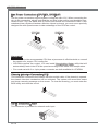
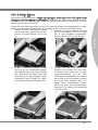
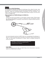
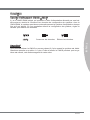
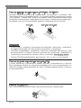
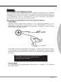
Gold arrow
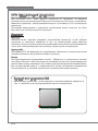
Introduction to AM3 CPU
The surface of CPU. Remember to apply some thermal paste on it for better heat
dispersion.

En-7
English
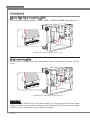
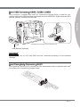
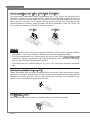
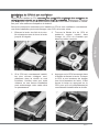
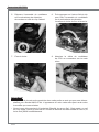
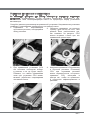
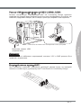
CPU & Cooler Installation
When you are installing the CPU, make sure the CPU has a cooler attached on the top
to prevent overheating. Meanwhile, do not forget to apply some thermal paste on CPU
before installing the heat sink/cooler fan for better heat dispersion.
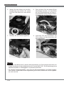
Follow the steps below to install the CPU & cooler correctly. Wrong installation will
cause the damage of your CPU & mainboard.
Pull the lever sideways away from
the socket. Make sure to raise the
lever up to a 90-degree angle.
1.
Look for the gold arrow of the CPU.
The gold arrow should point as shown
in the picture. The CPU can only t in
the correct orientation.
2.
If the CPU is correctly installed, the
pins should be completely embedded
into the socket and can not be seen.
Please note that any violation of the
correct installation procedures may
cause permanent damages to your
mainboard.
3. Press the CPU down rmly into the
socket and close the lever. As the
CPU is likely to move while the lever
is being closed, always close the
lever with your ngers pressing tightly
on top of the CPU to make sure the
CPU is properly and completely
embedded into the socket.
4.

En-8
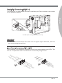
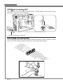
MS-7623 Mainboard
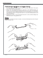
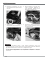
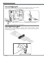
Position the cooling set onto the
retention mechanism.
Hook one end of the clip to hook
rst.
5.
Then press down the other end of the
clip to fasten the cooling set on the
top of the retention mechanism.
Locate the Fix Lever and lift up it .
6.
Fasten down the lever.7. Attach the CPU Fan cable to the CPU
fan connector on the mainboard.
8.
Important
Mainboard photos shown in this section are for demonstration of the cooler installation
for Socket AM3 CPUs only. The appearance of your mainboard may vary depending
on the model you purchase.
While disconnecting the Safety Hook from the xed bolt, it is necessary to keep an
eye on your ngers, because once the Safety Hook is disconnected from the xed
bolt, the xed lever will spring back instantly.
•
•

En-9
English
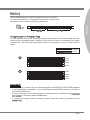
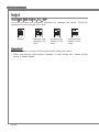
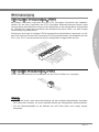
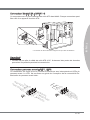
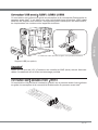
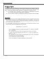
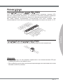
Memory
These DIMM slots are used for installing memory modules.
For more information on compatible components, please visit
http://www.msi.com/index.php?func=testreport
DDR3
240-pin, 1.5V
48x2=96 pin 72x2=144 pin
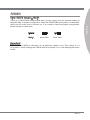
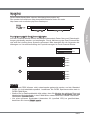
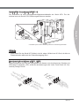
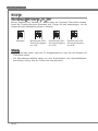
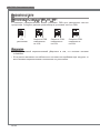
Dual-Channel mode Population Rule
In Dual-Channel mode, the memory modules can transmit and receive data with two
data bus lines simultaneously. Enabling Dual-Channel mode can enhance the system
performance. The following illustrations explain the population rules for Dual-Channel
mode.
Installed
Empty
1
DIMM1
DIMM2
DIMM3
DIMM4
2
DIMM1
DIMM2
DIMM3
DIMM4
Important
DDR3 memory modules are not interchangeable with DDR2 and the DDR3 standard
is not backwards compatible. You should always install DDR3 memory modules in
the DDR3 DIMM slots.
In Dual-Channel mode, make sure that you install memory modules of the same type
and density in dierent channel DIMM slots.
To enable successful system boot-up, always insert the memory modules into the
DIMM1 rst.
•
•
•

En-10
MS-7623 Mainboard
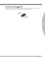
Installing Memory Modules
The memory module has only one notch on the center and will only t in the right
orientation.
Insert the memory module vertically into the DIMM slot. Then push it in until the
golden nger on the memory module is deeply inserted in the DIMM slot. The plastic
clip at each side of the DIMM slot will automatically close when the memory module
is properly seated.
Manually check if the memory module has been locked in place by the DIMM slot
clips at the sides.
Important
You can barely see the golden nger if the memory module is properly inserted in the
DIMM slot.
Notch
Volt
1.
2.
3.

En-11
English
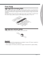
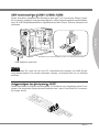
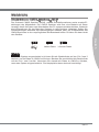
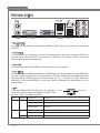
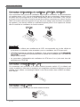
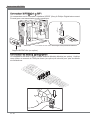
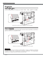
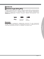
Power Supply
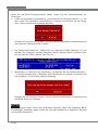
ATX 24-pin Power Connector: JPWR1
This connector allows you to connect an ATX 24-pin power supply. To connect the ATX
24-pin power supply, make sure the plug of the power supply is inserted in the proper
orientation and the pins are aligned. Then push down the power supply rmly into the
connector.
You may use the 20-pin ATX power supply as you like. If you’d like to use the 20-pin
ATX power supply, please plug your power supply along with pin 1 & pin 13.
13.+3.3
V
1.+3.3
V
14.-12V
2.+3.3
V
15.Ground
3
.Ground
16.PS-ON
#
4.+5
V
17.Ground
5
.Ground
18.Ground
6.+5
V
19.Ground
7
.Ground
22.+5
V
10.+12V
20.Res
8.PW
R O
K
23.+5
V
11
.+12V
21.+5
V
9.5VSB
24.Ground
12.+3.3
V
ATX 4-pin Power Connector: JPWR2
This power connector is used to provide power to the CPU.
4.+12V
2
.Ground
3.+12V
1
.Ground
Important
Make sure that all the connectors are connected to proper ATX power supplies to
ensure stable operation of the mainboard.
Power supply of 400 watts (and above) is highly recommended for system stability.
•
•

En-12
MS-7623 Mainboard
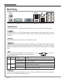
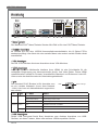
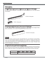
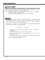
Back Panel
Mouse/Keyboard
The standard PS/2
®
mouse/keyboard DIN connector is for a PS/2
®
mouse/keyboard.
Serial Port
The serial port is a 16550A high speed communications port that sends/ receives
16 bytes FIFOs. You can attach a serial mouse or other serial devices directly to the
connector.
VGA Port
The DB15-pin female connector is provided for monitor.
HDMI Port
The High-Denition Multimedia Interface (HDMI) is an all-digital audio/video interface
capable of transmitting uncompressed streams. HDMI supports all TV format, including
standard, enhanced, or high-denition video, plus multi-channel digital audio on a single
cable.
LAN
The standard RJ-45 LAN jack is for connection to
the Local Area Network (LAN). You can connect a
network cable to it.
LED Color LED State Condition
Left Yellow O LAN link is not established.
On(Steady state) LAN link is established.
On(brighter & pulsing) The computer is communicating with another computer on the LAN.
Right Green O 10 Mbit/sec data rate is selected.
On 100 Mbit/sec data rate is selected.
Orange On 1000 Mbit/sec data rate is selected.
USB Ports
The USB (Universal Serial Bus) port is for attaching USB devices such as keyboard,
mouse, or other USB-compatible devices.
▶
▶
▶
▶
▶
▶
Mouse
Serial Port
LAN
Line-In
Line-Out
Mic
RS-Out
CS-Out
SS-Out
USB Ports
Keyboard
USB Ports
VGA Port HDMI Port
Yellow Green/ Orange
Page is loading ...
Page is loading ...
Page is loading ...
Page is loading ...
Page is loading ...
Page is loading ...
Page is loading ...
Page is loading ...
Page is loading ...
Page is loading ...
Page is loading ...
Page is loading ...
Page is loading ...
Page is loading ...
Page is loading ...
Page is loading ...
Page is loading ...
Page is loading ...
Page is loading ...
Page is loading ...
Page is loading ...
Page is loading ...
Page is loading ...
Page is loading ...
Page is loading ...
Page is loading ...
Page is loading ...
Page is loading ...
Page is loading ...
Page is loading ...
Page is loading ...
Page is loading ...
Page is loading ...
Page is loading ...
Page is loading ...
Page is loading ...
Page is loading ...
Page is loading ...
Page is loading ...
Page is loading ...
Page is loading ...
Page is loading ...
Page is loading ...
Page is loading ...
Page is loading ...
Page is loading ...
Page is loading ...
Page is loading ...
Page is loading ...
Page is loading ...
Page is loading ...
Page is loading ...
Page is loading ...
Page is loading ...
Page is loading ...
Page is loading ...
Page is loading ...
Page is loading ...
Page is loading ...
Page is loading ...
Page is loading ...
Page is loading ...
Page is loading ...
Page is loading ...
Page is loading ...
Page is loading ...
Page is loading ...
Page is loading ...
Page is loading ...
Page is loading ...
Page is loading ...
Page is loading ...
Page is loading ...
Page is loading ...
Page is loading ...
Page is loading ...
Page is loading ...
Page is loading ...
Page is loading ...
Page is loading ...
Page is loading ...
Page is loading ...
Page is loading ...
Page is loading ...
Page is loading ...
Page is loading ...
Page is loading ...
Page is loading ...
Page is loading ...
Page is loading ...
Page is loading ...
Page is loading ...
Page is loading ...
Page is loading ...
Page is loading ...
Page is loading ...
Page is loading ...
Page is loading ...
Page is loading ...
Page is loading ...
Page is loading ...
Page is loading ...
Page is loading ...
Page is loading ...
Page is loading ...
Page is loading ...
Page is loading ...
Page is loading ...
Page is loading ...
Page is loading ...
Page is loading ...
Page is loading ...
Page is loading ...
Page is loading ...
Page is loading ...
Page is loading ...
Page is loading ...
Page is loading ...
Page is loading ...
Page is loading ...
Page is loading ...
Page is loading ...
Page is loading ...
Page is loading ...
-
 1
1
-
 2
2
-
 3
3
-
 4
4
-
 5
5
-
 6
6
-
 7
7
-
 8
8
-
 9
9
-
 10
10
-
 11
11
-
 12
12
-
 13
13
-
 14
14
-
 15
15
-
 16
16
-
 17
17
-
 18
18
-
 19
19
-
 20
20
-
 21
21
-
 22
22
-
 23
23
-
 24
24
-
 25
25
-
 26
26
-
 27
27
-
 28
28
-
 29
29
-
 30
30
-
 31
31
-
 32
32
-
 33
33
-
 34
34
-
 35
35
-
 36
36
-
 37
37
-
 38
38
-
 39
39
-
 40
40
-
 41
41
-
 42
42
-
 43
43
-
 44
44
-
 45
45
-
 46
46
-
 47
47
-
 48
48
-
 49
49
-
 50
50
-
 51
51
-
 52
52
-
 53
53
-
 54
54
-
 55
55
-
 56
56
-
 57
57
-
 58
58
-
 59
59
-
 60
60
-
 61
61
-
 62
62
-
 63
63
-
 64
64
-
 65
65
-
 66
66
-
 67
67
-
 68
68
-
 69
69
-
 70
70
-
 71
71
-
 72
72
-
 73
73
-
 74
74
-
 75
75
-
 76
76
-
 77
77
-
 78
78
-
 79
79
-
 80
80
-
 81
81
-
 82
82
-
 83
83
-
 84
84
-
 85
85
-
 86
86
-
 87
87
-
 88
88
-
 89
89
-
 90
90
-
 91
91
-
 92
92
-
 93
93
-
 94
94
-
 95
95
-
 96
96
-
 97
97
-
 98
98
-
 99
99
-
 100
100
-
 101
101
-
 102
102
-
 103
103
-
 104
104
-
 105
105
-
 106
106
-
 107
107
-
 108
108
-
 109
109
-
 110
110
-
 111
111
-
 112
112
-
 113
113
-
 114
114
-
 115
115
-
 116
116
-
 117
117
-
 118
118
-
 119
119
-
 120
120
-
 121
121
-
 122
122
-
 123
123
-
 124
124
-
 125
125
-
 126
126
-
 127
127
-
 128
128
-
 129
129
-
 130
130
-
 131
131
-
 132
132
-
 133
133
-
 134
134
-
 135
135
-
 136
136
-
 137
137
-
 138
138
-
 139
139
-
 140
140
-
 141
141
-
 142
142
-
 143
143
-
 144
144
-
 145
145
-
 146
146


MSI 880GM-E41 Owner's manual
- Category
- Motherboards
- Type
- Owner's manual
- This manual is also suitable for
Ask a question and I''ll find the answer in the document
Finding information in a document is now easier with AI
in other languages
- français: MSI 880GM-E41 Le manuel du propriétaire
- Deutsch: MSI 880GM-E41 Bedienungsanleitung
- русский: MSI 880GM-E41 Инструкция по применению
Related papers
-
MSI 760GM-P35 User manual
-
-
-
-
-
-
MSI G52-75991XR Owner's manual
-
-
-
Other documents
-
Asus 90NB03RB-M01420 Datasheet
-
Gigabyte GA-880GM-D2H User manual
-
-
-
Arctic MX-2 Installation guide
-
-
Fujitsu D2917 User manual
-
-
 SLI S1689 User manual
-
SPEEDLINK PECOS 420W ATX User guide
