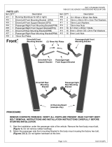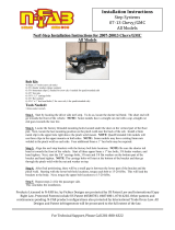
Hoop II Step Installation Instructions
Part No’s: 106331 / 106332 / 106334 / 106337
Chevy/GMC ’11-’19 Silverado/Sierra 2500-3500 All Cabs (Diesel)
Diagram A
Diagram
B
DIAGRAMS A, B, C & D ARE VIEWED FROM THE PASSENGER SIDE
Diagram
C
Diagram
D
Page 1
Black DEF
Tank
For model year
2017 & newer,
go to pages 3
and 4

Hoop II Step Installation Instructions
Part No’s: 106331 / 106332 / 106334 / 106337
Quality and Style that Endures
Follow the diagram and the written
directions carefully for a proper, safe
installation.
Should you encounter an unusual,
unforeseen problem, contact our
Technical Help Line
7:00 AM – 3:00 PM Pacific Time
(951) 719-1068
Visit our web-site at
www.CARR.com
Warranty Information
on our website
Carr Pattern Co., Inc.
1. These steps mount to an extremely strong part of your vehicle, the back side of its rocker
panels. For the proper position of the step, the front edge of the seat while in normal
driving position should be in line with the center of the step. For personal preference or to
avoid any obstruction that may be on the backside of the rocker panel, the step can be
moved towards the front or the rear of the vehicle.
2. For the front driver side, take the Mounting Brackets and slide them both up along the
back groove of the Black DEF Tank and than to the right so that the Mounting Brackets
are resting on the inside of the Pinch weld. See Diagram A & B. IMPORTANT: There is
a wire harness on the backside of the Body Metal. Make sure each Mounting Bracket
is flat against the Body Metal and not resting on the wire harness. If the wire harness
is between the Mounting Bracket and the Body Metal, serious damage could occur to
your vehicle's electrial system.
3. Take the Step Casting with the 1/4" hardware provided and hand-tighten the Step Casting
to the Mounting Brackets. Dia. C.
4. Position the step assembly in the desired position. Find the center of each Mounting
Bracket and mark two vertical lines on the painted surface of the body metal. Distance
between the two vertical lines need to be 8 3/8". See Diagram C.
5. Remove the 1/4" hardware and the step from the Mounting Brackets. Also, move the
Mounting Brackets away from the vertical marked lines for drilling out the holes.
6. At each mark vertical line, measure up from the edge of the Pinch Weld 1/2" and mark
another line forming a cross-hair mark. Diagram C.
7. Center punch the center of each cross-hair mark. Drill out the centers with a 1/8" drill bit
and than go back and drill holes with a 11/32" drill bit. Remove all burrs.
8. Take the 5/16" hardware provided and hand tighten the Mounting Brackets to the Body
Metal. NOTE: We suggest using Loctite when installing these bolts. IMPORTANT: The
holes in the Mounting Brackets are threaded. Make sure you hand tighten the 5/16 bolts
several turns before final tightening. Failure to do this may strip out the threaded holes.
Pulling down on the end of the Mounting Brackets where the Black DEF Tank is located
will help align the 5/16" bolt with the threaded holes. Filing holes larger in the Body Metal
may be necessary if the holes don't align. Leave the 5/16" hardware loose. See Diagram D.
9. Replace the Step Casting on the Mounting Brackets and securely tighten with your 5/32"
Allen Wrench and 7/16" wrench. Securely tighten the 5/16" hardware.
10. The hex sheet metal screws provided are not necessary for the step where the Black
DEF Tank is located. The other three steps will use the hex sheet metal screw. To install
the hex sheet metal screws, take a 1/8" drill bit and drill out the top holes on each
Mounting Bracket. Take the sheet metal screws and securely tighten.
11. For all the other Step Castings, follow the same steps above, leaving out all references to
the Black DEF Tank.
12. Use silicone on all drilled areas to insure a better weather resistant installation.
13. Your steps are ready for use.
WARNINGS!
Do not over tighten the nuts and bolts or damage to the castings and or stripping of the threads could result.
FOR SAFE AND PROPER USAGE OF THIS PRODUCT, THE MOUNTING INSTRUCTIONS MUST BE FOLLOWED CAREFULLY AND COMPLETELY.
The manufacturer and distributor of this product are in no way responsible for the consumer’s failure to adhere to the warnings and directions of these instructions in the
event of damage to the consumer’s vehicle, other properties and or personal injury.
Vehicle Application:
CHEVY
‘11-'19 Sierra/Silverado 2500-
3500 All Cabs (Diesel)
(Diesel only)
MATERIAL NEEDED:
Drill motor, 11/32” drill bit, 1/8” drill bit,
pencil, flat blade screw driver or 5/16"
socket, center punch, one ½” wrenches,
one 7/16” wrench, 10mm wrench, 5/32"
Allen Wrench, Loctite and silicone.
MATERIAL FURNISHED:
Two step castings, four mounting brackets,
instruction page and two hardware packs.
(Not all hardware may be used)
WAX YOUR STEP ON A
REGULAR BASIS TO
MAINTAIN ITS LUSTER
Carr Pattern Co., Inc.
Warranty Policy
Finishes: Limited Lifetime
Structural Warranty: Limited Lifetime
Warranty Conditions:
a. All warranties start from consumer’s date of purchase.
b. A new product will be sent out immediately to replace
a warranty claim.
c. The above guidelines apply only to the Original
Purchaser.
d. Original proof of purchase must be submitted for all
warranty and returns issues.
Warranty Limitations:
a. Warranty coverage extends ONLY to repair or
replacement of the CARR product. This warranty does
not cover the cost of labor, transportation, installation
or removal of the product.
b. Warranty coverage does not extend to damage caused
by: collision, fire, theft, freezing, vandalism, riot,
explosion or object striking the product, or misuse of
the product and/or the vehicle on which the product is
being installed.
c. Warranty coverage does not extend to damage caused
by: airborne fallout (chemicals, tree sap, etc.), stones,
hail, earthquake, water or flood, windstorm, lightning,
the application of chemicals or sealants subsequent to
manufacture.
d. Warranty coverage does not extend to damages caused
by: normal wear and tear, abuse, modification or
improper installation of the product.
e. Warranty coverage does not extend to any economic
loss or extra expense including (without limitation),
payment for the loss of time or pay, inconvenience,
storage, loss of vehicle use, vehicle rental expense,
equipment rental expense, lodging, meals, or other
travel costs.
Other Terms:
This warranty gives you specific legal rights and you may
also have other rights that vary from state to state. CARR
does not authorize any person to create for it any other
obligation or liability in connection with its products.
ANY IMPLIED WARRANTY OF
MERCHANTABILITY OR FITNESS FOR A
PARTICULAR PURPOSE APPLICABLE TO THIS
PRODUCT IS LIMITED IN DURATION TO THE
DURATION OF THIS WRITTEN WARRANTY.
PERFORMANCE OF REPAIRS AND NEEDED
ADJUSTMENTS IS THE EXCULSIVE REMEDY
UNDER THIS WRITTEN WARRANTY OR ANY
IMPLIED WARRANTY. CARR SHALL NOT BE
LIABLE FOR INCIDENTAL OR CONSEQUENTIAL
DAMAGES RESULTING FROM BREACH OF THIS
WRITTEN WARRANTY.*
*Some states do not allow limitations on how long an
implied warranty will last or the exclusion or limitation of
incidental or consequential damages, so that above
limitations or exclusions may not apply to you.
Guarantee: Every attempt has been made to manufacture
and distribute the finest quality products available. Our
manufactured products are guaranteed to be free of defects
due to workmanship or materials. Distributed products are
subject to manufacturer’s warranty only.
Page 2

1. Under the passenger front
door, remove the black DEF
plastic tank cover from your
vehicle. You will need a
10mm socket to remove the
four bolts. Keep these bolts
for reinstallation.
2. With the dimension
provided, cut the two slots
out on this cover. It is
recommended to use a
Dremel or similar tool to
grind these slots. Cutting
with a saw may crack the
plastic.
3. Bend the protruding tab down
to allow the front Mounting
Bracket to be in its proper
position. Channel Locks or
similar tool will make this
easier.
4. Slide the Mounting Brackets
behind the rocker panel and
in front of the DEF tank as
indicated. The left Mounting
Bracket will only move so far
due to interference from an
inner brace.
Hoop II Step Installation Instructions
Part No’s: 106331 / 106332 / 106334 / 106337
Chevy/GMC ’17 – ‘19 Silverado/Sierra 2500-3500 All Cabs (Diesel)
Page 3

5. Place the Step Casting on the
Mounting Brackets. Take the ¼”
hardware provided and hand
tighten the hardware.
6. Reinstall the DEF tank cover.
Slide the Mounting Bracket/Step
Casting assembly so that the
back of the Mounting Brackets
line up with the slots in the DEF
tank cover. Mark the lines on the
vehicle’s body metal as indicated
on the drawing. Make sure the
8 3/8” vertical lines are on center
with
the Mounting Brackets.
7. Once again, remove the DEF tank
cover. Also remove the Step Casting
from the Mounting Brackets. Move
the Mounting Brackets to the side.
Center punch the center of each
cross-hair mark. Drill out the
centers with a 1/8" drill bit and then
go back and drill out the holes with
a 11/32" drill bit. Remove all burrs.
Refer to Step 8 on Page 2 for
installing 5/16” hardware.
8. Reinstall the DEF tank cover. Refer
to Steps 9-13 on Page 2 for final
installation of this and all others
steps. NOTE: To insure both steps
are in a similar position on the front
doors, when installing the front
driver Hoop II step refer to the
position of the step that you just
installed on the front passenger side.
Page 4
Hoop II Step Installation Instructions
Part No’s: 106331 / 106332 / 106334 / 106337
Chevy/GMC ’17 – ‘19 Silverado/Sierra 2500-3500 All Cabs (Diesel)
-
 1
1
-
 2
2
-
 3
3
-
 4
4
Carr 106332 Installation guide
- Type
- Installation guide
Ask a question and I''ll find the answer in the document
Finding information in a document is now easier with AI
Related papers
-
Carr 106332-1 Installation guide
-
Carr 193002 Installation guide
-
Carr 129772-1 Installation guide
-
Carr 111141-1 Installation guide
-
Carr 193022 Installation guide
-
Carr 127441-1 Installation guide
-
Carr 200031 Installation guide
-
Carr 200042 Installation guide
-
Carr 451011-1 Installation guide
-
Carr 129777 Installation guide
Other documents
-
 CPW WJ20-0004 User manual
-
 APS IB03DJJ7A User manual
-
CURT 18202 User manual
-
 TMI Products 1968-72 Nova Rear Seat Installation guide
-
Bestop powerboard nx Installation Instructions Manual
-
 N-Fab HPC0780CC-TX Owner's manual
-
Air Lift 59501 Installation guide
-
Reese 30035 Installation guide
-
Go Rhino D24049T Installation guide


