Page is loading ...

July 2018
Instruction Book IB182071EN
Remote Power Racking System
(RPR-2)
Supercedes October 2013
Eective
RPR-2 Low Profile Shown

ii
Instruction Book IB182071EN
July 2018
Remote Power Racking System
(RPR-2)
www.eaton.com
m WARNING
IMPROPERLY INSTALLING OR MAINTAINING THESE PRODUCTS CAN
RESULT IN DEATH, SERIOUS PERSONAL INJURY OR PROPERTY DAMAGE.
READ AND UNDERSTAND THESE INSTRUCTIONS BEFORE ATTEMPTING
ANY UNPACKING, ASSEMBLY, OPERATION OR MAINTENANCE OF THE
CIRCUIT BREAKERS.
INSTALLATION OR MAINTENANCE SHOULD BE ATTEMPTED ONLY
BY QUALIFIED PERSONNEL. THIS INSTRUCTION BOOK SHOULD NOT
BE CONSIDERED ALL INCLUSIVE REGARDING INSTALLATION OR
MAINTENANCE PROCEDURES. IF FURTHER INFORMATION IS REQUIRED,
YOU SHOULD CONSULT EATON’S ELECTRICAL SERVICES & SYSTEMS.
THE CIRCUIT BREAKERS DESCRIBED IN THIS BOOK ARE DESIGNED AND
TESTED TO OPERATE WITHIN THEIR NAMEPLATE RATINGS. OPERATION
OUTSIDE OF THESE RATINGS MAY CAUSE THE EQUIPMENT TO FAIL,
RESULTING IN DEATH, BODILY INJURY AND PROPERTY DAMAGE.
ALL SAFETY CODES, SAFETY STANDARDS AND/OR REGULATIONS AS
THEY MAY BE APPLIED TO THIS TYPE OF EQUIPMENT MUST BE STRICTLY
ADHERED TO.
THESE VACUUM REPLACEMENT CIRCUIT BREAKERS ARE DESIGNED TO
BE INSTALLED PURSUANT TO THE AMERICAN NATIONAL STANDARDS
INSTITUTE (ANSI). SERIOUS INJURY, INCLUDING DEATH, CAN RESULT
FROM FAILURE TO FOLLOW THE PROCEDURES OUTLINED IN THIS
MANUAL.
DISCLAIMER OF WARRANTIES AND LIMITATION OF LIABILITY
The information, recommendations, descriptions and safety notations in this document are based on Eaton’s experience and judgment and
may not cover all contingencies. If further information is required, an Eaton sales office should be consulted. Sale of the product shown in
this literature is subject to the terms and conditions outlined in appropriate Eaton selling policies or other contractual agreement between
Eaton and the purchaser.
THERE ARE NO UNDERSTANDINGS, AGREEMENTS, WARRANTIES, EXPRESSED OR IMPLIED, INCLUDING WARRANTIES OF FITNESS
FOR A PARTICULAR PURPOSE OR MERCHANTABILITY, OTHER THAN THOSE SPECIFICALLY SET OUT IN ANY EXISTING CONTRACT
BETWEEN THE PARTIES. ANY SUCH CONTRACT STATES THE ENTIRE OBLIGATION OF EATON. THE CONTENTS OF THIS DOCUMENT
SHALL NOT BECOME PART OF OR MODIFY ANY CONTRACT BETWEEN THE PARTIES.
In no event will Eaton be responsible to the purchaser or user in contract, in tort (including negligence), strict liability or other-wise for any
special, indirect, incidental or consequential damage or loss whatsoever, including but not limited to damage or loss of use of equipment,
plant or power system, cost of capital, loss of power, additional expenses in the use of existing power facilities, or claims against the
purchaser or user by its customers resulting from the use of the information, recommendations and descriptions contained herein. The
information contained in this manual is subject to change without notice.
This product was manufactured by Eaton at the Power Breaker
Center (PBC): 310 Maxwell Avenue, Greenwood, SC 29646.
All possible contingencies which may arise during installation,
operation or maintenance, and all details and variations of this
equipment do not purport to be covered by these instructions. If
further information is desired by purchaser regarding his particular
installation, operation or maintenance of particular equipment,
contact a Eaton representative.

iii
Instruction Book IB182071EN
July 2018
Remote Power Racking System
(RPR-2)
www.eaton.com
Table of Contents
SECTION 1: INTRODUCTION 4
1.1 VISUAL PRESENTATION 4
1.2 QUICK RESPONSE CODE 4
SECTION 2: SAFE PRACTICES 6
SECTION 3: RECEIVING, HANDLING, AND STORAGE 7
3.1 RECEIVING 7
3.2 HANDLING 7
3.3 STORAGE 7
3.4 RPR-2 APPROXIMATE WEIGHTS 7
SECTION 4: RACKING PROCEDURES 10
4.1 INSERTING POWER CIRCUIT BREAKERS 10
4.2 REMOVING POWER CIRCUIT BREAKERS 12
SECTION 5: WARRANTY 13
5.1 GENERAL 13
5.2 PROCEDURE FOR POWER MODULE REMOVAL 13
5.3 REMOVING UPS MODULE FROM RPR-2 DEVICE 14
5.4 REPLACEMENT OF THE UPS MODULE BATTERIES 15
SECTION 6: REPLACEMENT PARTS 16
6.1 GENERAL 16
6.2 ORDERING INSTRUCTIONS 16
APPENDIX A: ITE-HK AIR CIRCUIT BREAKER 17
A.1 INSERTION PROCEDURE USING THE RPR-2 17
A.2 REMOVAL PROCEDURE USING THE RPR-2 18
APPENDIX B: GE AM-5 CIRCUIT BREAKER 19
B.1 INSERTION PROCEDURE USING THE RPR-2 19
B.2 REMOVAL PROCEDURE USING THE RPR-2 20
APPENDIX C: GE MAGNEBLAST VERTICAL LIFT 21
C.1 INSERTION PROCEDURE USING THE RPR-2 21
C.2 REMOVAL PROCEDURE USING THE RPR-2 23
APPENDIX D: WESTINGHOUSE DH AIR CIRCUIT BREAKERS 24
D.1 INSERTION PROCEDURE USING THE RPR-2 24
D.2 REMOVAL PROCEDURE USING THE RPR-2 25

4
Instruction Book IB182071EN
July 2018
Remote Power Racking System
(RPR-2)
www.eaton.com
SECTION 1: INTRODUCTION
Eaton’s RPR-2 provides a means of remotely racking most Power
Circuit Breakers that utilize the rotation of a shaft for insertion
and removal. The person can be 25 feet or more away from the
switchgear door during the racking process. This need for distance
away from the switchgear is due to safety precautions from potential
Arc Flash occurrences.
Electric arcs result from thermal ionization that occurs when
current flow is interrupted by the separation of conductors. Thermal
ionization can generate temperatures as high as 35,000
o
F. Conductor
materials melt into metal vapor and the surrounding air is ionized.
If the arc is outside the interrupting chamber of a power circuit
breaker, then a violent explosion occurs resulting in an inferno of
ionized gases, molten debris, metal shrapnel, and a flash of light
(Arc Flash). When Arc Flash initiates in a switchgear cabinet, the
rapidly escalating pressure will dislodge compartment doors and
side sheets of the switchgear and turn hardware into high-speed
projectiles.
Arc Flash levels are a function of circuit voltage, maximum
available short circuit current at the point of flashover, conditions
of confinement, and the distance between the point of flashover
and the point of measurement. Many Arc Flash incidences with
Low Voltage and Medium Voltage switchgear occur during the
process of inserting and removing (racking) Power Circuit Breakers
in switchgear cubicles. Personnel are typically within two feet of
the front of the power circuit breaker during the racking process
and this close proximity to an Arc Flash can cause serious injury.
Published records indicate over 2000 people are treated annually in
burn centers from exposure to Arc Flash and some result in death.
A company’s financial exposure is rarely less than $100,000 for
medical care and insurance claims per incident. NFPA 70E provides
guidance for the requirements of personal protective equipment
(PPE) to protect personnel from arc flash exposure. PPE for high
levels of Arc Flash can be bulky, hot, and uncomfortable. This may
dissuade personnel from wearing proper protection. The best way
to limit exposure to Arc Flash during the process of racking power
circuit breakers is to put more distance between the person and the
possible point of exposure.
Eaton’s RPR-2 can allow personnel to wear a lower level of PPE,
increasing worker comfort and mobility, while operating the RPR-2
from an increased distance from the power circuit breaker. Since
personnel can be outside the Arc Flash protection boundary while
operating the RPR-2, the power circuit breaker door does not have
to be closed during the racking process. Closed door racking is
possible with many designs, however structure modifications may
be necessary. Customer surveys have shown that any remote
racking device must:
•
Be easily and quickly set up
•
Does not require programming
•
Be portable and easy to maneuver
•
Be capable of racking numerous manufacturers’ models of power
circuit breakers
The RPR-2 system is the solution that provides the value and
features customers request.
The RPR-2 unit comes pre-programmed for up to eight different
power circuit breakers. The programs are pre-selected by the
customer to meet their requirements, and the unit is programmed
per these requirements at the Power Breaker Center. No additional
programming is necessary; simply select the applicable program for
the power circuit breaker.
1.1 VISUAL PRESENTATION
Eaton provides additional documentation designed to enhance the
technical information provided in this instruction booklet for the
RPR-2. The digital supplemental booklet features informative videos
intended to assist with the RPR-2. The document is available for
immediate access at www.eaton.com/RPR-2.
1.2 QUICK RESPONSE CODE
There is a quick response code (QR Code) on the escutcheon of the
head unit and UPS sleeve of the RPR-2. This QR Code is a matrix
barcode that provides direct access to download RPR-2 specific
documentation, such as product instruction booklets and a visual
presentation documentation. See Figure 1.1 for the featured RPR-2
QR Code.
ote:N A smart phone with an adequate QR Code Scanner application
must be used. Downloading content may incur data charges from the
mobile service provider.
Figure 1.1. Quick Response Code
RPR-2 QR Code

5
Instruction Book IB182071EN
July 2018
Remote Power Racking System
(RPR-2)
www.eaton.com
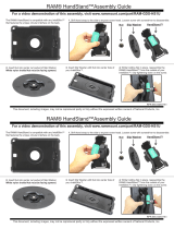
Table 1. RPR-2 and RPR-2 Plus Dimensions
Profile Type
Overall
Height
Stanchion
Height
Max. Racking
Height
Min. Racking
Height Width Depth
360
o
Rotational
Clearance
A B C D E F G
RPR-2 Universal Profile 100” 98” 81” 4.875” 28” 29” 36”
RPR-2 Medium Profile 88” 86” 68” 4.875” 28” 29” 36”
RPR-2 Low Profile 68” 66” 48” 4.875” 28” 29” 36”
E
G
F
B
C
D
A

6
Instruction Book IB182071EN
July 2018
Remote Power Racking System
(RPR-2)
www.eaton.com
SECTION 2: SAFE PRACTICES
Eaton’s RPR-2 assists in the insertion and removal of power circuit
breakers. Although proper use of the RPR-2 reduces the probability
of injury by increasing the distance of the qualified operating
personnel from the arc flash boundary, must follow local safe
practices and the requirements of personal protective equipment
(PPE) to protect personnel from arc flash exposure as determined by
NFPA 70E.
m WARNING
TO PROTECT THE PERSONNEL ASSOCIATED WITH INSTALLATION,
OPERATION, AND MAINTENANCE OF POWER CIRCUIT BREAKERS, THE
FOLLOWING PRACTICES MUST BE FOLLOWED:
•
Only qualified persons, as defined in the National Electrical
Safety Code, who are familiar with the installation and
maintenance of power circuit breakers and equipment,
should be permitted to insert or remove power circuit
breakers.
•
Read these instructions carefully before attempting any
installation, operation or maintenance of power circuit
breakers.
•
Refer to the OEM power circuit breaker instruction manual
for proper installation and operation procedures of each
power circuit breaker the RPR-2 is intended to rack.
•
Power circuit breakers are equipped with safety interlocks.
Do not defeat them. This may result in death, bodily injury or
equipment damage.
•
Do not leave the breaker in an intermediate position in the
cell. Always have the breaker either in the Test or Connected
position. Failure to do so could result in a flash over and
possible death, personnel injury or property damage.
•
Always remove the RPR-2 device from the breaker before
attempting to charge, close or operate the breaker.

7
Instruction Book IB182071EN
July 2018
Remote Power Racking System
(RPR-2)
www.eaton.com
SECTION 3: RECEIVING, HANDLING, AND
STORAGE
Remote Power Racking units are subjected to complete factory
production tests and inspection before being packed. They are
shipped in containers designed to provide maximum protection to
the equipment during shipment and storage and at the same time to
provide convenient handling.
3.1 RECEIVING
Until the RPR-2 unit is ready to be delivered to the switchgear site
for usage, DO NOT remove it from the shipping container. If the
RPR-2 unit is to be placed in storage, maximum protection can be
obtained by keeping it in its container. A 120V power supply will be
needed for the UPS at this time.
Upon receipt of the equipment, inspect the containers for any signs
of damage or rough handling. Open the containers carefully to avoid
any damage to the contents. Use a nail puller rather than a crow bar
when required.
When opening the containers, be careful that any loose items or
hardware are not discarded with the packing material. Check the
contents of each package against the packing list.
Examine the RPR-2 unit for any signs of shipping damage such
as broken, missing or loose hardware, damaged or deformed
components. File claims immediately with the carrier if damage or
loss is detected and notify the nearest Eaton’s Electrical Service and
Systems Office.
After examining the unit place the RPR-2 in a location which has a
120V power supply for the UPS.
Figure 3.1. Typical Tools and Accessories
shelter from sun, rain, snow, corrosive fumes, dust, dirt falling
objects, excessive moisture, etc. must be provided. If the building is
not heated, containers should be arranged to permit free circulation
of air on all sides and temporary heaters should be used to minimize
condensation. Moisture can cause rusting of metal parts. A heat
level of approximately 400 watts for each 100 cubic feet of volume is
recommended with the heaters distributed uniformly throughout the
structure near the floor.
3.2 HANDLING
The RPR-2 unit shipping containers are designed to be handled by
a fork lift truck. If containers must be skidded for any distance, it is
preferable to use roller conveyors or individual pipe rollers. When the
RPR-2 unit is ready for use, it can be rolled upright with the casters
or tilted back and rolled on the larger wheels.
3.3 STORAGE
If the RPR-2 unit is to be placed in storage, maximum protection
can be obtained by keeping it shielded with the provided cover
(Figure 3.3). Before placing it in storage, checks should be made to
make sure that the RPR-2 unit is free from shipping damage and is
in satisfactory operating condition. The RPR-2 unit is shipped with
the Transport Latch engaged (Figure 3.2). The RPR-2 unit requires
a 120V power supply for the UPS during storage and must remain
plugged in during this time.
Outdoor storage is NOT recommended. Indoor storage should
be in a building with sufficient heat and circulation to prevent
condensation. The building must be well drained and a temporary
Figure 3.2. RPR-2 Transport Latch
Figure 3.3. RPR-2 Storage Cover
3.4 RPR-2 APPROXIMATE WEIGHTS
Refer to Table 2.
Table 2. RPR-2 Weight by Type
Type LBs
RPR-2 Universal Profile 315
RPR-2 Medium Profile 310
RPR-2 Low Profile 300

8
Instruction Book IB182071EN
July 2018
Remote Power Racking System
(RPR-2)
www.eaton.com
Figure 3.5. Profile External View of RPR-2
Profile External View of RPR-2 (Univeral Profile Shown)
1 Stanchion 5 UPS Power Cable 9 Counterweight Cable
2 Status Light Tower 6 Jog Button 10 Power Module Cable
3 Control Pendant 7 Mechanical Over-Torque Protector
4 Storage Compartment 8 Insertion Shaft
1
2
3
4
6
7
8
5
9
10

9
Instruction Book IB182071EN
July 2018
Remote Power Racking System
(RPR-2)
www.eaton.com
2
1
3
4
5
6
Figure 3.6. Detail View of RPR-2 Head Unit
Front External View
1 Transport Latch 4 Insertion Shaft Lock 7 Nameplate
2 Computer Access Port 5 Power Switch 8 Foot Brake
3 Power Cable 6 Pendant Connection Port
Rear External View
1 Control Pendant Cable Standoff 3 Insertion Shaft 5 UPS Display
2 Jog Button 4 Mechanical Over-Torque Protector 6 UPS Power Button (ON/OFF)
1
2
3
4
5
6
8
7

10
Instruction Book IB182071EN
July 2018
Remote Power Racking System
(RPR-2)
www.eaton.com
SECTION 4: RACKING PROCEDURES
ote:N REFER TO THE APPENDIX FOR ADDITIONAL BREAKER SPECIFIC
RACKING PROCEDURES.
4.1 INSERTING POWER CIRCUIT BREAKERS
1) Follow all procedures defined by company’s Personal Protective
Equipment and Safety policy. Follow all precautions and
requirements listed in the circuit breaker IB for racking the
breaker.
2) Move the RPR-2 unit in front of the switchgear cell. Open
the cell door to allow for access to the rotary type racking
mechanism of the breaker. If the cell has closed door racking
capability, insert the racking adaptor through the provided
opening with the cell door closed.
3) Verify that the power circuit breaker is open and ready to be
racked in from the correct position. The position depends
on what type of power circuit breaker is being inserted.
This position is determined by the ability to rack in the given
power circuit breaker from the position that it can be racked
completely into the Connected position without needing any
adjustments (foot pedal pressed etc.). In most cases this is the
Test position in the cell. This can be confirmed by referring to
the breaker’s Instruction Book.
6) Turn on the power to the Power Module with the Power
Switch. (Figure 3.6)
7) The choice of the perf-a-torque will be dependent on the
breaker that is being racked. The PT-50 will be used on all
medium voltage circuit breakers and the PT-30 will be used on
all the low voltage circuit breakers.
For changing the perf-a-torque:
A 1/8” allen wrench is required to loosen the setscrew. Once the
attached perf-a-torque has been removed, replace with the desired
perf-a-torque model as indicated above. Using the 1/8” allen wrench,
secure the perf-a-torque to the racking shaft.
Setscrew Tightness:
After the RPR-2 has been used to rack several breakers, check that
the perf-a-torque is tight on the racking shaft. Tighten as needed.
4) If engaged, release the Transport Latch to allow for vertical
movement of the Power Module. (Figure 3.3)
5) Turn on the Powerware UPS for the RPR-2 by pressing the
On button for approximately five seconds and allow for the
unit to initialize. (Figure 4.5) For all other menu settings and
features, please refer to the UPS instruction CD.
Figure 4.1. RPR-2 Control Panel
Fusion Controller
Breaker Select Button
Insert / Remove Switch
Figure 4.2. Height Adjustment of Power Module
Figure 4.3. RPR-2 Control Pendant
Status Indicator Light
Insert Button
Remove Button
Figure 4.4. Perf-A-Torque Models
8) Select the correct breaker program on the Power Module by
pressing and releasing the Breaker Select Button until the desired
program is displayed on the Fusion Controller. (Figure 4.1)
9) Select the INSERT direction with the Insert/Remove switch.
(Figure 4.1)

11
Instruction Book IB182071EN
July 2018
Remote Power Racking System
(RPR-2)
www.eaton.com
9) Select the correct racking adaptor for the breaker being
inserted. (Figure 3.1) If applicable, place the racking adaptor on
the breaker’s racking mechanism shaft. Position the RPR-2 shaft
with the racking adaptor. Turn the Insertion Shaft Lock to Unlatched
position to allow for connection the RPR-2 into the racking adaptor
on the power circuit breaker. (Figure 3.6) If necessary, the Jog
button (Figure 3.6) can be pressed to rotate the shaft for correct
alignment (amber pendant and tower light will illuminate). Horizontal
alignment can be achieved with the casters and vertical alignment by
raising or lowering the Power Module. (Figure 4.2)
10) Once the RPR-2 is connected, properly adjust the unit toward
the cell to insure the proper amount of travel is available for the
power circuit breaker insertion process. When an adequate amount
of travel distance is achieved, the green tower light will illuminate.
11) Engage the foot brake on the RPR-2 truck by stepping down
on the lever. (Figure 4.6) Verify that the correct power circuit breaker
program and the Insert direction are selected by viewing the LCD
screen on the Fusion Controller (Figure 4.1).
m WARNING
SELECTION OF THE INCORRECT POWER CIRCUIT BREAKER PROGRAM MAY
RESULT IN THE RPR-2 UNIT SIGNALING COMPLETION OF THE INSERTION
CYCLE WITH THE POWER CIRCUIT BREAKER ONLY PARTIALLY INSERTED.
12) Take the Pendant and move a safe distance away from
front of the power circuit breaker. (The distance should be
predetermined through Arc Flash calculations.)
13) When area is clear, depress and hold the Insert button (white
with black arrow) on the pendant. (Figure 4.3) This will initiate
the insertion process on the RPR-2 unit. The amber light on the
pendant and on the tower light will illuminate while the power
circuit breaker is in the insertion process.
ote:N If at any time during the insertion process the Insert button is released,
the tower lights and pendant light will not be illuminated.
14) When the power circuit breaker is in the Connected position,
the red tower light will illuminate and the amber light on the
pendant will turn off. This indicates that it is now safe to
approach the power circuit breaker.
m WARNING
IF AT ANY TIME DURING THE INSERTION PROCESS AN OVER-TORQUE
OCCURS THE AMBER LIGHT ON THE PENDANT AND TOWER WILL FLASH.
(THE AUTO REVERSE SELECTION IS NOTED ON THE NAMEPLATE OF THE
RPR-2 UNIT.)
• IF THE AUTO-REVERSE FUNCTION IS SELECTED IN THIS SITUATION
THE RPR-2 WILL THEN INITIALIZE THE REMOVAL PROCESS. ONCE THIS
PROCESS IS COMPLETED THE GREEN AND AMBER LIGHTS ON THE
LIGHT TOWER WILL FLASH AND THE AMBER LIGHT ON THE PENDANT
WILL TURN OFF INDICATING IT IS SAFE TO APPROACH THE POWER
CIRCUIT BREAKER.
• IF THE AUTO-REVERSE FUNCTION IS NOT SELECTED, PRESS AND HOLD
THE REMOVE BUTTON (BLACK WITH WHITE ARROW) ON THE PENDANT.
WHEN THE POWER CIRCUIT BREAKER IS COMPLETELY REMOVED, THE
AMBER LIGHT ON THE PENDANT WILL TURN OFF AND THE GREEN
AND AMBER TOWER LIGHTS WILL FLASH INDICATING IT IS SAFE TO
APPROACH THE POWER CIRCUIT BREAKER.
15) To disconnect the RPR-2 unit, push the unit toward the
switchgear cell to disengage the brakes. Lift the brake lever up
to engage the holding magnet.
Figure 4.5. UPS Power Button Figure 4.6. Foot Brake Set
Figure 4.7. Racking Adapter Connected To Breaker

12
Instruction Book IB182071EN
July 2018
Remote Power Racking System
(RPR-2)
www.eaton.com
m WARNING
SELECTION OF THE INCORRECT POWER CIRCUIT BREAKER PROGRAM MAY
RESULT IN THE RPR-2 UNIT SIGNALING COMPLETION OF THE REMOVAL
CYCLE WITH THE POWER CIRCUIT BREAKER ONLY PARTIALLY REMOVED.
12) Take the Pendant and move a safe distance away from front
of the power circuit breaker. (The distance should be predetermined
through Arc Flash calculations.)
m WARNING
IF AT ANY TIME DURING THE REMOVAL PROCESS AN OVER-TORQUE
OCCURS THE AMBER LIGHT ON THE PENDANT AND TOWER WILL
FLASH. THE UNIT WILL NOT REMOVE THE BREAKER FURTHER UNTIL THE
PROBLEM IS RESOLVED. FOLLOW THE COMPANY’S SAFETY PROCEDURES
WHEN APPROACHING THE SWITCHGEAR CELL.
13) When area is clear, depress and hold the Remove button
(black with white arrow) on the pendant. (Figure 4.3) This will
initiate the removal process on the RPR-2 unit. The amber light
on the pendant and on the tower light will illuminate while the
power circuit breaker is in the removal process.
ote:N If at any time during the removal process the Remove button is
released, the tower lights and pendant light will not be illuminated.
14) When the power circuit breaker is in the Disconnected
position, the green tower light will illuminate and the amber
light on the pendant will turn off. This indicates that it is now
safe to approach the power circuit breaker.
15) To disconnect the RPR-2 unit, push the unit toward the
switchgear cell to disengage the brakes. Lift the brake lever up
to engage the holding magnet.
16) Turn the Insertion Shaft Lock to the Latched position. Push the
unit towards the breaker until the insertion shaft latches.
17) Pull the unit away from the switchgear, while disconnecting
the insertion shaft from the racking adaptor.
18) Remove the racking adaptor from the breaker and place it back
into the storage box on the RPR-2 unit.
19) Turn Off the Power Module with the Power Switch. To turn
off the UPS, press and hold the Off button for approximately
five seconds.
20) Lower the Power module to the lowest position and engage
the Transport Latch. (Figure 3.3) The pendant can be stored
by wrapping the cord around the post at the base of the RPR-2
unit. (Figure 3.5) Place the RPR-2 unit cover over the base
while in storage. (Figure 3.4)
21) The UPS should be connected to a wall receptacle when not in
use to maintain a charge on the batteries.
16) Turn the Insertion Shaft Lock to the Latched position. Push the
unit forward until the insertion shaft latches.
17) Pull the unit away from the switchgear, while disconnecting
the insertion shaft from the racking adaptor.
18) Remove the racking adaptor from the breaker and place it back
into the storage box on the RPR-2 unit.
19) Turn Off the Power Module with the Power Switch. To turn
off the UPS, press and hold the Off button for approximately
five seconds.
20) Lower the Power module to the lowest position and engage
the Transport Latch. (Figure 3.3) The pendant can be stored
by wrapping the cord around the post at the base of the RPR-2
unit. (Figure 3.5) Place the RPR-2 unit cover over the base
while in storage. (Figure 3.4)
21) The UPS should be connected to a wall receptacle when not in
use to maintain a charge on the batteries.
4.2 REMOVING POWER CIRCUIT BREAKERS
1) Follow all procedures defined by company’s Personal Protective
Equipment and Safety policy and the precautions and racking
instructions in the breaker IB.
2) Move the RPR-2 unit in front of the switchgear cell. Open
the cell door to allow for access to the rotary type racking
mechanism of the breaker. If the cell has closed door racking
capability, insert the racking adaptor through the provided
opening with the cell door closed.
3) Verify that the power circuit breaker is open and ready to be
racked out from the Connected position.
4) If engaged, release Transport Latch to allow for vertical
movement of the Power Module. (Figure 3.6)
5) Turn on the Powerware UPS for the RPR-2 by pressing the
On button for approximately five seconds and allow for the
unit to initialize. (Figure 4.5) For all other menu settings and
features, please refer to the UPS instruction CD.
6) Turn on the power to the Power Module with the Power
Switch. (Figure 3.6)
7) Select the correct breaker program on the Power Module by
pressing and releasing the Breaker Select Button until the
desired program is displayed on the Fusion Controller. (Figure
4.1) Before attempting to rack the circuit breaker, ensure the
nameplate matches the predetermined circuit breaker program
on the Eaton display of the Fusion Controller.
8) Select the REMOVE direction on the Insert/Remove switch.
(Figure 4.1)
9) Select the correct racking adaptor for the breaker being
inserted. (Figure 3.1) If applicable, place the racking adaptor
on the breaker’s racking mechanism shaft. Position the RPR-2
shaft with the racking adaptor. Turn the Insertion Shaft Lock to
Unlatched position to allow for connection the RPR-2 into the
racking adaptor on the power circuit breaker. (Figure 3.6) If
necessary, the Jog button (Figure 3.6) can be pressed to rotate
the shaft for correct alignment (amber pendant and tower light
will illuminate). Horizontal alignment can be achieved with the
casters and vertical alignment by raising or lowering the Power
Module. (Figure 4.2)
10) Once the RPR-2 is connected, properly adjust the unit away
from the cell to insure the proper amount of travel is available
for the power circuit breaker insertion process. When an
adequate amount of travel distance is achieved, the red tower
light will illuminate.
11) Engage the foot brake on the RPR-2 truck. Verify that the
correct power circuit breaker program and the Remove
direction are selected by viewing the LCD screen on the Fusion
Controller (Figure 4.1).

13
Instruction Book IB182071EN
July 2018
Remote Power Racking System
(RPR-2)
www.eaton.com
SECTION 5: WARRANTY
5.1 GENERAL
All Standard Remote Power Racking Systems (RPR-2) are furnished
with a Powerware UPS system and are covered by the warranty
stated in Eaton’s Electrical Services and Systems Selling Policy
25-000, except the warranty is extended for a total of three (3) years
from the date of shipment. The Warranty expiration date is printed
on the nameplate mounted on the Power Module (Figure 3.6). If the
unit does not function as described in this instruction book, do not
attempt any repair.
ote:N Attempts to repair the unit will void the warranty.
m WARNING
DO NOT ATTEMPT TO INSERT OR REMOVE ANY POWER CIRCUIT BREAKER
WITH A REMOTE POWER RACKING SYSTEM (RPR-2) THAT IS NOT
FUNCTIONING PROPERLY. FAILURE TO FOLLOW THIS WARNING COULD
RESULT IN DEATH, SERIOUS PERSONAL INJURY OR PROPERTY DAMAGE.
PLUGGING THE POWER SUPPLY CABLE OF THE POWER MODULE DIRECTLY
INTO A WALL OUTLET VOIDS THE WARRANTY. THE POWER MODULE
MUST BE PLUGGED INTO THE UPS SYSTEM ONLY.
THE COUNTERWEIGHT CABLE IS MANUFACTURED WITH AN INFUSED
LUBRICANT THAT MAY MIGRATE OUT AND DRIP DOWN ON THE BASE.
THIS SHOULD SIMPLY BE WIPED UP.
Contact the Power Breaker Center (PBC) immediately by calling
toll free (877) 276-9379. Normal business hours are 7:30 AM until
4:30 PM, Monday through Friday, except for holidays. If the call is
placed after or before normal business hours, you may leave a voice
message. A Power Breaker Center representative will return your call
within 24 hours (48 hours on holidays and weekends), determine the
cause of the problem, and advise if any replacement components or
modules are required to restore the Remote Power Racking System
to normal operation.
If it is necessary to replace the Power Module, UPS system, or other
components, the representative will initiate an express air shipment
that typically arrives within 48 hours after the PBC representative
contacts the customer. The representative will also convey any
special instructions, if required, for return of the defective unit. The
UPS unit must remain plugged in when not in use.
Upon receipt of the replacement equipment, inspect the container
for any signs of damage or rough handling. Open the container and
save all hardware and packing material. These materials as well
as the shipping container will be used to repack and return the
defective equipment to the PBC. A set of shipping instructions and a
shipping label will be in the container. Be careful not to discard these
items. There is no charge for the return shipment if packed in the
original shipping container.
5.2 PROCEDURE FOR POWER MODULE REMOVAL
ote:N This procedure requires assistance.
1) Lay the RPR-2 over on a brace approximately half way up the
stanchion. Make sure the Power Module is located closest to
the top end of the stanchion for removal.
2) Move the Power Module up the stanchion until the
counterweight hits the bottom allowing for some slack in the
connection cable.
3) Using a 7/32 Allen wrench, remove the cable retaining hex
socket button head from the bottom of the Power Module,
retain lock washer.
4) With some slack on the cable, slide the end of the connecting
cable out of the slot in the bottom of the Power Module.
5) Tape the cable end to the stanchion to keep the cable in line
with the openings.
6) With one person holding each side of the Power Module, slide it
off the end of the stanchion.
Figure 5.1. RPR-2 In Power Module Removal Position (Unit
Supported By Standard Post For Demonstration Purposes)
Figure 5.2. Removing Cable Retaining Hex Socket Button Head
From Power Module
Figure 5.3. Bottom View of Power Module

14
Instruction Book IB182071EN
July 2018
Remote Power Racking System
(RPR-2)
www.eaton.com
5.3 REMOVING UPS MODULE FROM RPR-2 DEVICE
In certain cases where the UPS needs to be replaced due to a
warranty repair, the UPS will need to be removed.
1. Locate the UPS module on the lower base of the RPR-2.
2. Remove the UPS retaining bracket hardware (x4), and store the
UPS retaining bracket for reassembly. (Figure 5.4)
3. Disconnect the 120V power supply from the UPS Module
(Figure 5.5) and carefully slide the UPS module forward to
remove it from the UPS sleeve. (Figure 5.6)
Figure 5.4. Removing UPS Retaining Bracket (x4)
Figure 5.5. Disconnecting 120V Power Supply From UPS Module Figure 5.8. Unpluging UPS Module
Figure 5.6. Removing UPS Module From RPR-2 Device Figure 5.9. Removing UPS Battery Cover Plate Hardware (x1)
Figure 5.7. Removing UPS Module Front Cover
5.4 REPLACEMENT OF THE UPS MODULE BATTERIES
Once the UPS module has been removed from the RPR-2 device,
the UPS module batteries can be replaced.
ote:N All three batteries should be replaced at the same time.
1. Remove the front cover of the UPS module by pulling the left
two corners away from the unit. (Figure 5.7)
2. Disconnect the battery by pulling apart the battery terminals.
(Figure 5.8)

15
Instruction Book IB182071EN
July 2018
Remote Power Racking System
(RPR-2)
www.eaton.com
Figure 5.11. Removing UPS Battery Pack
Figure 5.12. Disconnecting UPS Battery Lead
Figure 5.10. Removing UPS Battery Cover
3. With the battery disconnected, the internal battery cover plate
may be removed. Remove the battery cover plate retaining
hardware (x1) (Figure 5.9) and slide the battery cover plate in an
upward and outward direction. (Figure 5.10)
4. Remove the UPS module battery pack from the UPS module.
(Figure 5.11)
5. To ensure replacement is correct, replace each battery one at a
time. The wiring connections will remain the same. Each wire
connection is marked for clarity. (Figure 5.12)
6. Once the batteries have been replaced, the battery pack plastic
tray should be re-taped to secure a tight fit when returning it to
the UPS module.
7. Slide the battery pack back into the UPS module and replace
the internal battery cover plate using the existing cover plate
hardware.
8. Reconnect the main battery terminals and replace the UPS
module front cover.
9. Reconnect thew 120V power supply to the UPS module.
10. The RPR-2 head unit can now be reconnected.
11. Contact your local recycling or hazardous waste center for the
information on proper disposal of the used batteries.
m WARNING
• DO NOT DISPOSE OF BATTERY OR BATTERIES IN A FIRE. EXPLOSION
MAY OCCUR.
• PROPER DISPOSAL OF BATTERIES IS REQUIRED. REFER TO YOUR
LOCAL CODES FOR DISPOSAL REQUIREMENTS.
• DO NOT ATTEMPT TO OPEN OR DESTROY THE BATTERY. TOXIC AND
HARMFUL MATERIAL CAN DAMAGE THE SKIN AND EYES.
• DO NOT DISCARD THE UPS OR THE UPS BATTERIES IN THE
STANDARD TRASH. THIS PRODUCT CONTAINS SEALED, LEAD-ACID
BATTERIES AND MUST BE DISPOSED OF PROPERLY. FOR ANY QUESTIONS
PLEASE CONTACT YOUR LOCAL RECYCLING OR HAZARDOUS WASTE
CENTER.
5.5 REMOVING/REPLACING THE UPS MODULE SLEEVE
In certain cases the UPS module sleeve may need to be replaced
due to damage and/or upgrading from previous RPR-2 UPS revision.
Follow the steps listed in section 5.3 to remove the UPS module
from the sleeve.
1. Remove the ¼-20 nuts (x4) that hold the sleeve to the RPR-2
base (Figure 5.13)
ote:N When upgrading from the previous RPR-2 UPS revision, discard
the entire UPS assembly and replace it with the new UPS sleeve and
module.
2. To replace/install the UPS sleeve, align the ¼-20 bolts (x4) to
the existing holes on the RPR-2 base.
3. Securely fasten the sleeve to the base using ¼-20 nuts (x4) and
install the UPS module using the method from section 5.3 in
reverse order.
Figure 5.13. Removing the UPS Sleeve

16
Instruction Book IB182071EN
July 2018
Remote Power Racking System
(RPR-2)
www.eaton.com
SECTION 6: REPLACEMENT PARTS
6.1 GENERAL
In order to minimize production downtime, it is recommended that
an adequate quantity of spare parts be carried in stock. The quantity
will vary from customer to customer, depending upon the service
severity and continuity requirements. Each customer should develop
his own level based on operating experience.
6.2 ORDERING INSTRUCTIONS
a. Always specify all information printed on the nameplate.
b. Describe the item, give the style number, and specify the
quantity required.
c. Specify the method of shipping desired.
d. Send all orders or correspondence to the nearest Eaton’s
Electrical Services & Systems sales office or contact the PBC at
(877) 276-9379 for assistance.

17
Instruction Book IB182071EN
July 2018
Remote Power Racking System
(RPR-2)
www.eaton.com
APPENDIX A:
ITE-HK AIR CIRCUIT BREAKER
A.1 INSERTION PROCEDURE USING THE RPR-2
1) Follow all procedures defined by company’s Personal Protective
Equipment and Safety policy. Follow all precautions and
requirements listed in the circuit breaker IB for racking the
breaker.
2) Move the RPR-2 unit in front of the switchgear cell. Open
the cell door to allow for access to the rotary type racking
mechanism of the breaker. If the cell has closed door racking
capability, insert the racking adaptor through the provided
opening with the cell door closed.
3) Verify that the power circuit breaker is open and ready to be
racked in from the correct position. The position depends
on what type of power circuit breaker is being inserted.
This position is determined by the ability to rack in the given
power circuit breaker from the position that it can be racked
completely into the Connected position without needing any
adjustments (foot pedal pressed etc.). This is the Test position
for HK breakers.
4) If engaged, release the Transport Latch to allow for vertical
movement of the Power Module. (Figure 3.3)
5) Turn on the Powerware UPS for the RPR-2 by pressing the
On button for approximately five seconds and allow for the
unit to initialize. (Figure 4.5) For all other menu settings and
features, please refer to the UPS instruction CD.
6) Turn on the power to the Power Module with the Power
Switch. (Figure 3.6)
7) Select the correct breaker program on the Power Module by
pressing and releasing the Breaker Select Button until the
desired program is displayed on the Fusion Controller. (Figure
4.1)
8) Select the INSERT direction with the Insert/Remove switch.
(Figure 4.1)
9) Select the correct racking adaptor for the breaker being
inserted. (Figure 3.1) Place the racking adaptor on the breaker’s
racking mechanism shaft. Position the RPR-2 shaft with the
racking adaptor. Turn the Insertion Shaft Lock to Unlatched
position to allow for connection the RPR-2 into the racking
adaptor on the power circuit breaker. (Figure 3.6) An extension
can be used if a longer length is needed. If necessary, the Jog
button (Figure 3.6) can be pressed to rotate the shaft for correct
alignment (amber pendant and tower light will illuminate).
Horizontal alignment can be achieved with the casters and
vertical alignment by raising or lowering the Power Module.
(Figure 4.2)
10) Once the RPR-2 is connected, properly adjust the unit toward
the cell to insure the proper amount of travel is available for
the power circuit breaker insertion process. When an adequate
amount of travel distance is achieved, the green tower light will
illuminate.
11) Engage the foot brake on the RPR-2 truck by stepping down
on the lever. (Figure 4.6) Verify that the correct power circuit
breaker program and the Insert direction are selected by
viewing the LCD screen on the Fusion Controller (Figure 4.1).
m WARNING
SELECTION OF THE INCORRECT POWER CIRCUIT BREAKER PROGRAM MAY
RESULT IN THE RPR-2 UNIT SIGNALING COMPLETION OF THE INSERTION
CYCLE WITH THE POWER CIRCUIT BREAKER ONLY PARTIALLY INSERTED.
12) In order to start racking the HK air breaker, the racking shaft
interlock must be held aside. Do this by holding the interlock
paddle aside while pressing and holding the RPR-2 Jog button
for the duration of one cycle. (Figure A.1) this will turn the
breakers racking shaft far enough to hold the interlock paddle
aside.
13) Take the Pendant and move a safe distance away from
front of the power circuit breaker. (The distance should be
predetermined through Arc Flash calculations.)
14) When area is clear, depress and hold the Insert button (white
with black arrow) on the pendant. (Figure 4.3) This will initiate
the insertion process on the RPR-2 unit. The amber light on the
pendant and on the tower light will illuminate while the power
circuit breaker is in the insertion process.
ote:N If at any time during the insertion process the Insert button is
released, the tower lights and pendant light will not be illuminated.
15) When the power circuit breaker is in the Connected position,
the red tower light will illuminate and the amber light on the
pendant will turn off. This indicates that it is now safe to
approach the power circuit breaker.
m WARNING
IF AT ANY TIME DURING THE INSERTION PROCESS AN OVER-TORQUE
OCCURS THE AMBER LIGHT ON THE PENDANT AND TOWER WILL FLASH.
(THE AUTO REVERSE SELECTION IS NOTED ON THE NAMEPLATE OF THE
RPR-2 UNIT.)
• IF THE AUTO-REVERSE FUNCTION IS SELECTED IN THIS SITUATION
THE RPR-2 WILL THEN INITIALIZE THE REMOVAL PROCESS. ONCE THIS
PROCESS IS COMPLETED THE GREEN AND AMBER LIGHTS ON THE
LIGHT TOWER WILL FLASH AND THE AMBER LIGHT ON THE PENDANT
WILL TURN OFF INDICATING IT IS SAFE TO APPROACH THE POWER
CIRCUIT BREAKER.
Figure A.1. Interlock Paddle Held Aside and Jog Button Pressed
To Start ITE-HK Racking Process

18
Instruction Book IB182071EN
July 2018
Remote Power Racking System
(RPR-2)
www.eaton.com
• IF THE AUTO-REVERSE FUNCTION IS NOT SELECTED, PRESS AND HOLD
THE REMOVE BUTTON (BLACK WITH WHITE ARROW) ON THE PENDANT.
WHEN THE POWER CIRCUIT BREAKER IS COMPLETELY REMOVED, THE
AMBER LIGHT ON THE PENDANT WILL TURN OFF AND THE GREEN
AND AMBER TOWER LIGHTS WILL FLASH INDICATING IT IS SAFE TO
APPROACH THE POWER CIRCUIT BREAKER.
16) To disconnect the RPR-2 unit, push the unit toward the
switchgear cell to disengage the brakes. Lift the brake lever up
to engage the holding magnet.
17) Turn the Insertion Shaft Lock to the Latched position. Push the
unit forward until the insertion shaft latches.
18) Pull the unit away from the switchgear, while disconnecting
the insertion shaft from the racking adaptor.
19) Remove the racking adaptor from the breaker and place it back
into the storage box on the RPR-2 unit.
20) Turn Off the Power Module with the Power Switch. To turn
off the UPS, press and hold the Off button for approximately
five seconds.
21) Lower the Power module to the lowest position and engage
the Transport Latch. (Figure 3.3) The pendant can be stored
by wrapping the cord around the post at the base of the RPR-2
unit. (Figure 3.5) Place the RPR-2 unit cover over the base
while in storage. (Figure 3.4)
22) The UPS should be connected to a wall receptacle when not in
use to maintain a charge on the batteries.
A.2 REMOVAL PROCEDURE USING THE RPR-2
1) Follow all procedures defined by company’s Personal Protective
Equipment and Safety policy and the precautions and racking
instructions in the breaker IB.
2) Move the RPR-2 unit in front of the switchgear cell. Open
the cell door to allow for access to the rotary type racking
mechanism of the breaker. If the cell has closed door racking
capability, insert the racking adaptor through the provided
opening with the cell door closed.
3) Verify that the power circuit breaker is open and ready to be
racked out from the Connected position.
4) If engaged, release Transport Latch to allow for vertical
movement of the Power Module. (Figure 3.6)
5) Turn on the Powerware UPS for the RPR-2 by pressing the
On button for approximately five seconds and allow for the
unit to initialize. (Figure 4.5) For all other menu settings and
features, please refer to the UPS instruction CD.
6) Turn on the power to the Power Module with the Power
Switch. (Figure 3.6)
7) Select the correct breaker program on the Power Module by
pressing and releasing the Breaker Select Button until the
desired program is displayed on the Fusion Controller. (Figure
4.1)
8) Select the REMOVE direction on the Insert/Remove switch.
(Figure 4.1)
9) Select the correct racking adaptor for the breaker being
inserted. (Figure 3.1) Place the racking adaptor on the breaker’s
racking mechanism shaft. Position the RPR-2 shaft with the
racking adaptor. Turn the Insertion Shaft Lock to Unlatched
position to allow for connection the RPR-2 into the racking
adaptor on the power circuit breaker. (Figure 3.6) An extension
can be used if a longer length is needed. If necessary, the Jog
button (Figure 3.6) can be pressed to rotate the shaft for correct
alignment (amber pendant and tower light will illuminate).
Horizontal alignment can be achieved with the casters and
vertical alignment by raising or lowering the Power Module.
(Figure 4.2)
10) Once the RPR-2 is connected, properly adjust the unit away
from the cell to insure the proper amount of travel is available
for the power circuit breaker insertion process. When an
adequate amount of travel distance is achieved, the red tower
light will illuminate.
11) Engage the foot brake on the RPR-2 truck. Verify that the
correct power circuit breaker program and the Remove
direction are selected by viewing the LCD screen on the Fusion
Controller (Figure 4.1).
12) While holding the interlock paddle aside, press and hold the
RPR-2 Jog button for the duration of one cycle. (Figure A.1)
This will turn the breakers racking shaft far enough to hold the
interlock paddle aside.
m WARNING
SELECTION OF THE INCORRECT POWER CIRCUIT BREAKER PROGRAM MAY
RESULT IN THE RPR-2 UNIT SIGNALING COMPLETION OF THE REMOVAL
CYCLE WITH THE POWER CIRCUIT BREAKER ONLY PARTIALLY REMOVED.
13) Take the Pendant and move a safe distance away from
front of the power circuit breaker. (The distance should be
predetermined through Arc Flash calculations.)
m WARNING
IF AT ANY TIME DURING THE REMOVAL PROCESS AN OVER-TORQUE
OCCURS THE AMBER LIGHT ON THE PENDANT AND TOWER WILL
FLASH. THE UNIT WILL NOT REMOVE THE BREAKER FURTHER UNTIL THE
PROBLEM IS RESOLVED. FOLLOW THE COMPANY’S SAFETY PROCEDURES
WHEN APPROACHING THE SWITCHGEAR CELL.
14) When area is clear, depress and hold the Remove button
(black with white arrow) on the pendant. (Figure 4.3) This will
initiate the removal process on the RPR-2 unit. The amber light
on the pendant and on the tower light will illuminate while the
power circuit breaker is in the removal process.
ote:N If at any time during the removal process the Remove button is
released, the tower lights and pendant light will not be illuminated.
15) When the power circuit breaker is in the Disconnected
position, the green tower light will illuminate and the amber
light on the pendant will turn off. This indicates that it is now
safe to approach the power circuit breaker.
16) To disconnect the RPR-2 unit, push the unit toward the
switchgear cell to disengage the brakes. Lift the brake lever up
to engage the holding magnet.
17) Turn the Insertion Shaft Lock to the Latched position. Push the
unit towards the breaker until the insertion shaft latches.
18) Pull the unit away from the switchgear, while disconnecting
the insertion shaft from the racking adaptor.
19) Remove the racking adaptor from the breaker and place it back
into the storage box on the RPR-2 unit.
20) Turn Off the Power Module with the Power Switch. To turn
off the UPS, press and hold the Off button for approximately
five seconds.
21) Lower the Power module to the lowest position and engage
the Transport Latch. (Figure 3.3) The pendant can be stored
by wrapping the cord around the post at the base of the RPR-2
unit. (Figure 3.5) Place the RPR-2 unit cover over the base
while in storage. (Figure 3.4)
22) The UPS should be connected to a wall receptacle when not in
use to maintain a charge on the batteries.

19
Instruction Book IB182071EN
July 2018
Remote Power Racking System
(RPR-2)
www.eaton.com
APPENDIX B:
GE AM-5 CIRCUIT BREAKER
B.1 INSERTION PROCEDURE USING THE RPR-2
m WARNING
ONLY USE THE “RAISE” LIFTING MECHANISM INTERFACE (INDICATED BY
THE ARROW IN FIGURE B.1) DURING RACKING OPERATIONS WITH
RPR-2 UNIT.
1) Follow all procedures defined by company’s Personal Protective
Equipment and Safety policy. Follow all precautions and
requirements listed in the circuit breaker IB for racking the
breaker.
2) Move the RPR-2 unit in front of the switchgear cell. Open
the cell door to allow for access to the rotary type racking
mechanism of the breaker. If the cell has closed door racking
capability, insert the racking adaptor through the provided
opening with the cell door closed.
3) Verify that the power circuit breaker is open and ready to be
racked in from the correct position. The position depends
on what type of power circuit breaker is being inserted.
This position is determined by the ability to rack in the given
power circuit breaker from the position that it can be racked
completely into the Connected position without needing any
adjustments (foot pedal pressed etc.). This is the Test position
for HK breakers.
4) If engaged, release the Transport Latch to allow for vertical
movement of the Power Module. (Figure 3.3)
5) Turn on the Powerware UPS for the RPR-2 by pressing the
On button for approximately five seconds and allow for the
unit to initialize. (Figure 4.5) For all other menu settings and
features, please refer to the UPS instruction CD.
6) Turn on the power to the Power Module with the Power
Switch. (Figure 3.6)
7) Select the correct breaker program on the Power Module by
pressing and releasing the Breaker Select Button until the
desired program is displayed on the Fusion Controller. (Figure
4.1)
8) Select the INSERT direction with the Insert/Remove switch.
(Figure 4.1)
9) Select the correct racking adaptor for the breaker being
inserted. (Figure 3.1) Place the racking adaptor on the breaker’s
racking mechanism shaft. Position the RPR-2 shaft with the
racking adaptor. Turn the Insertion Shaft Lock to Unlatched
position to allow for connection the RPR-2 into the racking
adaptor on the power circuit breaker. (Figure 3.6) An extension
can be used if a longer length is needed. If necessary, the Jog
button (Figure 3.6) can be pressed to rotate the shaft for correct
alignment (amber pendant and tower light will illuminate).
Horizontal alignment can be achieved with the casters and
vertical alignment by raising or lowering the Power Module.
(Figure 4.2)
10) Once the RPR-2 is connected, properly adjust the unit toward
the cell to insure the proper amount of travel is available for
the power circuit breaker insertion process. When an adequate
amount of travel distance is achieved, the green tower light will
illuminate.
11) Engage the foot brake on the RPR-2 truck by stepping down
on the lever. (Figure 4.6) Verify that the correct power circuit
breaker program and the Insert direction are selected by
viewing the LCD screen on the Fusion Controller (Figure 4.1).
m WARNING
SELECTION OF THE INCORRECT POWER CIRCUIT BREAKER PROGRAM MAY
RESULT IN THE RPR-2 UNIT SIGNALING COMPLETION OF THE INSERTION
CYCLE WITH THE POWER CIRCUIT BREAKER ONLY PARTIALLY INSERTED.
12) Take the Pendant and move a safe distance away from
front of the power circuit breaker. (The distance should be
predetermined through Arc Flash calculations.)
13) When area is clear, depress and hold the Insert button (white
with black arrow) on the pendant. (Figure 4.3) This will initiate
the insertion process on the RPR-2 unit. The amber light on the
pendant and on the tower light will illuminate while the power
circuit breaker is in the insertion process.
ote:N If at any time during the insertion process the Insert button is
released, the tower lights and pendant light will not be illuminated.
14) When the power circuit breaker is in the Connected position,
the red tower light will illuminate and the amber light on the
pendant will turn off. This indicates that it is now safe to
approach the power circuit breaker.
m NOTICE
IF AT ANY TIME DURING THE INSERTION PROCESS AN OVER-TORQUE
OCCURS THE AMBER LIGHT ON THE PENDANT AND TOWER WILL FLASH.
(THE AUTO REVERSE SELECTION IS NOTED ON THE NAMEPLATE OF THE
RPR-2 UNIT.)
• IF THE AUTO-REVERSE FUNCTION IS SELECTED IN THIS SITUATION
THE RPR-2 WILL THEN INITIALIZE THE REMOVAL PROCESS. ONCE THIS
PROCESS IS COMPLETED THE GREEN AND AMBER LIGHTS ON THE
LIGHT TOWER WILL FLASH AND THE AMBER LIGHT ON THE PENDANT
WILL TURN OFF INDICATING IT IS SAFE TO APPROACH THE POWER
CIRCUIT BREAKER.
Figure B.1. Only Use The “RAISE” Lifting Mechanism

20
Instruction Book IB182071EN
July 2018
Remote Power Racking System
(RPR-2)
www.eaton.com
• IF THE AUTO-REVERSE FUNCTION IS NOT SELECTED, PRESS AND HOLD
THE REMOVE BUTTON (BLACK WITH WHITE ARROW) ON THE PENDANT.
WHEN THE POWER CIRCUIT BREAKER IS COMPLETELY REMOVED, THE
AMBER LIGHT ON THE PENDANT WILL TURN OFF AND THE GREEN
AND AMBER TOWER LIGHTS WILL FLASH INDICATING IT IS SAFE TO
APPROACH THE POWER CIRCUIT BREAKER.
15) To disconnect the RPR-2 unit, push the unit toward the
switchgear cell to disengage the brakes. Lift the brake lever up
to engage the holding magnet.
16) Turn the Insertion Shaft Lock to the Latched position. Push the
unit forward until the insertion shaft latches.
17) Pull the unit away from the switchgear, while disconnecting
the insertion shaft from the racking adaptor.
18) Remove the racking adaptor from the breaker and place it back
into the storage box on the RPR-2 unit.
19) Turn Off the Power Module with the Power Switch. To turn
off the UPS, press and hold the Off button for approximately
five seconds.
20) Lower the Power module to the lowest position and engage
the Transport Latch. (Figure 3.3) The pendant can be stored
by wrapping the cord around the post at the base of the RPR-2
unit. (Figure 3.5) Place the RPR-2 unit cover over the base
while in storage. (Figure 3.4)
21) The UPS should be connected to a wall receptacle when not in
use to maintain a charge on the batteries.
B.2 REMOVAL PROCEDURE USING THE RPR-2
m WARNING
ONLY USE THE “RAISE” LIFTING MECHANISM INTERFACE (INDICATED BY
THE ARROW IN FIGURE B.1) DURING RACKING OPERATIONS WITH
RPR-2 UNIT.
1) Follow all procedures defined by company’s Personal Protective
Equipment and Safety policy and the precautions and racking
instructions in the breaker IB.
2) Move the RPR-2 unit in front of the switchgear cell. Open
the cell door to allow for access to the rotary type racking
mechanism of the breaker. If the cell has closed door racking
capability, insert the racking adaptor through the provided
opening with the cell door closed.
3) Verify that the power circuit breaker is open and ready to be
racked out from the Connected position.
4) If engaged, release Transport Latch to allow for vertical
movement of the Power Module. (Figure 3.3)
5) Turn on the Powerware UPS for the RPR-2 by pressing the
On button for approximately five seconds and allow for the
unit to initialize. (Figure 4.5) For all other menu settings and
features, please refer to the UPS instruction CD.
6) Turn on the power to the Power Module with the Power
Switch. (Figure 3.6)
7) Select the correct breaker program on the Power Module by
pressing and releasing the Breaker Select Button until the
desired program is displayed on the Fusion Controller. (Figure
4.1)
8) Select the REMOVE direction on the Insert/Remove switch.
(Figure 4.1)
9) Select the correct racking adaptor for the breaker being
inserted. (Figure 3.1) Place the racking adaptor on the breaker’s
racking mechanism shaft. Position the RPR-2 shaft with the
racking adaptor. Turn the Insertion Shaft Lock to Unlatched
position to allow for connection the RPR-2 into the racking
adaptor on the power circuit breaker. (Figure 3.6) An extension
can be used if a longer length is needed. If necessary, the Jog
button (Figure 3.6) can be pressed to rotate the shaft for correct
alignment (amber pendant and tower light will illuminate).
Horizontal alignment can be achieved with the casters and
vertical alignment by raising or lowering the Power Module.
(Figure 4.2)
10) Once the RPR-2 is connected, properly adjust the unit away
from the cell to insure the proper amount of travel is available
for the power circuit breaker insertion process. When an
adequate amount of travel distance is achieved, the red tower
light will illuminate.
11) Engage the foot brake on the RPR-2 truck. Verify that the
correct power circuit breaker program and the Remove
direction are selected by viewing the LCD screen on the Fusion
Controller (Figure 4.1).
m WARNING
SELECTION OF THE INCORRECT POWER CIRCUIT BREAKER PROGRAM MAY
RESULT IN THE RPR-2 UNIT SIGNALING COMPLETION OF THE REMOVAL
CYCLE WITH THE POWER CIRCUIT BREAKER ONLY PARTIALLY REMOVED.
12) Take the Pendant and move a safe distance away from
front of the power circuit breaker. (The distance should be
predetermined through Arc Flash calculations.)
m NOTICE
IF AT ANY TIME DURING THE REMOVAL PROCESS AN OVER-TORQUE
OCCURS THE AMBER LIGHT ON THE PENDANT AND TOWER WILL
FLASH. THE UNIT WILL NOT REMOVE THE BREAKER FURTHER UNTIL THE
PROBLEM IS RESOLVED. FOLLOW THE COMPANY’S SAFETY PROCEDURES
WHEN APPROACHING THE SWITCHGEAR CELL.
13) When area is clear, depress and hold the Remove button
(black with white arrow) on the pendant. (Figure 4.3) This will
initiate the removal process on the RPR-2 unit. The amber light
on the pendant and on the tower light will illuminate while the
power circuit breaker is in the removal process.
ote:N If at any time during the removal process the Remove button is
released, the tower lights and pendant light will not be illuminated.
14) When the power circuit breaker is in the Disconnected
position, the green tower light will illuminate and the amber
light on the pendant will turn off. This indicates that it is now
safe to approach the power circuit breaker.
15) To disconnect the RPR-2 unit, push the unit toward the
switchgear cell to disengage the brakes. Lift the brake lever up
to engage the holding magnet.
16) Turn the Insertion Shaft Lock to the Latched position. Push the
unit towards the breaker until the insertion shaft latches.
17) Pull the unit away from the switchgear, while disconnecting
the insertion shaft from the racking adaptor.
18) Remove the racking adaptor from the breaker and place it back
into the storage box on the RPR-2 unit.
19) Turn Off the Power Module with the Power Switch. To turn
off the UPS, press and hold the Off button for approximately
five seconds.
20) Lower the Power module to the lowest position and engage
the Transport Latch. (Figure 3.3) The pendant can be stored
by wrapping the cord around the post at the base of the RPR-2
unit. (Figure 3.5) Place the RPR-2 unit cover over the base
while in storage. (Figure 3.4)
21) The UPS should be connected to a wall receptacle when not in
use to maintain a charge on the batteries.
/