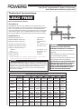
Watts HydroGuard Water Tempering Installation guide
- Type
- Installation guide

Lead Free
*
HydroGuard
®
Water Tempering
with Automatic Balancing System
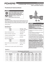
Technical Instructions
IS-P-RECIRCULATING_LOOP
Maximum Operating Pressure . . . . . . . . . . . . . . . . 125psi (861 kPa)
Maximum Hot Water Temperature . . . . . . . . . . . . . . 200°F (93°C)
Minimum Hot Water Supply Temp. . . . . . . . . . . . . . . 5°F (3°C) Above Set
Point**
Hot Water Inlet Temperature Range . . . . . . . . . . . . . 120 -180°F (49 - 82°C)
Cold Water Inlet Temperature Range . . . . . . . . . . . . 40 - 80°F (4 - 27°C)
Temperature Adjustment Range ***
Standard . . . . . . . . . . . . . . . . . . . . . . . . . . . 90 - 160°F (32 - 71°C)
Low . . . . . . . . . . . . . . . . . . . . . . . . . . . . . . 60 - 90°F (16 - 32°C)
Listing - Valve Only . . . . . . . . . . . . . . . . . . . . . . . ASSE 1017
Certified - Valve Only . . . . . . . . . . . . . . . . . . . . . . CSA B125
** With Equal Pressure
*** Note: Low limit cannot be less than the cold water temperature. For best operation,
hot water should be at least 5°F (3°C) above desired set point.
Specifications n
Description n
The HydroGuard
®
Lead Free
*
water tempering and recirculation loop is an eco-
nomical way to provide a safe, balanced system for stand-alone master tempering
valves. The system monitors return line temperature and automatically directs
water to the cold side of the tempering valve (if within set point) or to the hot water
source (below set point). This is accomplished with Powers exclusive automatic
balancing valve (ABV), featuring paraffin-based, advanced actuation technology.
Capacity n
Flow Capacity at 50-50 Mixed Ratio
Pressure Drop Across Valve
Model
Min. Flow
C
V
5psi 10psi 20psi 30psi 45psi 60psi
to ASSE 1017
(34 kPa) (69 kPa) (138 kPa) (207 kPa) (310 kPa) (414 kPa)
LFMM431
3 gpm
6.32
14 gpm 20 gpm 28 gpm 35 gpm 42 gpm 49 gpm
11 lpm 53 lpm 76 lpm 106 lpm 132 lpm 159 lpm 185 lpm
LFMM432
4 gpm
9.49
21 gpm 30 gpm 42 gpm 52 gpm 64 gpm 74 gpm
15 lpm 80 lpm 114 lpm 159 lpm 197 lpm 242 lpm 280 lpm
LFMM433
5 gpm
16.44
37 gpm 52 gpm 74 gpm 90 gpm 110 gpm 127 gpm
19 lpm 140 lpm 197 lpm 280 lpm 341 lpm 416 lpm 481 lpm
LFMM434
7 gpm
21.50
48 gpm 68 gpm 96 gpm 118 gpm 144 gpm 167 gpm
26 lpm 182 lpm 257 lpm 363 lpm 447 lpm 545 lpm 632 lpm
LFMM435
10 gpm
31.00
69 gpm 98 gpm 139 gpm 170 gpm 208 gpm 240 gpm
38 lpm 261 lpm 371 lpm 526 lpm 644 lpm 787 lpm 908 lpm
LFSH1432
1 gpm
8.54
19 gpm 27 gpm 38 gpm 47 gpm 57 gpm 66 gpm
4 lpm 72 lpm 102 lpm 144 lpm 178 lpm 216 lpm 250 lpm
LFSH1434
1 gpm
19.00
42 gpm 60 gpm 85 gpm 104 gpm 127 gpm 147 gpm
4 lpm 159 lpm 227 lpm 322 lpm 394 lpm 481 lpm 556 lpm
LFSH1435
5 gpm
30.00
67 gpm 95 gpm 134 gpm 164 gpm 201 gpm 232 gpm
19 lpm 254 lpm 360 lpm 507 lpm 621 lpm 761 lpm 878 lpm
LEAD FREE
*
TO ENSURE THE ACCURATE AND RELIABLE
OPERATION OF THIS PRODUCT, IT IS ESSENTIAL TO:
• Properly size each valve based on the individual
application.
• Properly design the recirculation system to minimize
pressure and temperature variations.
• Conduct an annual maintenance program to ensure
proper operation of all critical components.
THIS VALVE MUST BE USED IN CONJUNCTION WITH
TEMPERATURE ACTUATED POINT-OF-USE DEVICES
THAT COMPLY WITH ASSE 1016, 1069, OR 1070.
FAILURE TO COMPLY WITH PROPER INSTALLATION
INSTRUCTIONS COULD CONTRIBUTE TO VALVE
FAILURE, RESULTING IN IN JURY OR DEATH.
WARNING
!
*The wetted surface of this product contacted by consumable water contains less than 0.25% of lead by weight.
Please read and retain these instructions.
WARNING
!
Need for Periodic Inspection: Periodic inspection by a licensed contractor is
recommended. Corrosive water conditions, temperatures over 200°F, unauthor-
ized adjustments or repair could render the valve ineffective for service intend-
ed. Regular checking and cleaning of thermostat assembly helps to assure
maximum life and proper product function. Frequency of cleaning depends
upon local water conditions.

1. Installation should be in accordance with acceptable plumbing
practices. Flush all piping thoroughly before installation. Installation
and field adjustment are the responsibility of the installer.
2. Return loop assembly to be installed as close to building supply as
possible to prevent/minimize pressure uctuations.
3. Connect inlets, outlets and check for leaks.
4. Temperature Adjustment;
i) Turn off recirculation pump
ii) Open enough xtures to meet minimum ow requirement of:
LFMM431 = 3 GPM (11 LPM)
LFMM432 = 4 GPM (15 LPM)
LFMM433 = 5 GPM (19 LPM)
LFMM434 = 7 GPM (26 LPM)
LFMM435 = 10 GPM (38 LPM)
LFSH1432 = 1 GPM (4 LPM)
LFSH1434 = 1 GPM (4 LPM)
LFSH1435 = 5 GPM (19 LPM)
iii) Loosen temperature adjustment locknut located on top of the
bonnet.
iv) Turn temperature adjustment screw (located on top of the bon-
net) counterclockwise to increase or clockwise to decrease the
outlet temperature.
Allow valve temperature to settle in before making your next
adjustment.
v) When desired temperature is set, tighten the locknut. Turn recir-
culation pump back on. Close open fixtures.
5. Automatic Balancing Valve (ABV) Adjustment
i) Set ABV to full cold by turning knob to full clockwise position.
ii) Open enough xtures to meet minimum ow rate of the valve
(see above).
iii) Open ball valve and verify water is owing.
iv) Make sure water travels through the facility and stabilizes tem-
perature at the return thermometer.
v) While holding boiler return pipe, slowly rotate ABV knob coun-
terclockwise until warm water begins to ow. Stop rotating the
knob.
vi) Turn all xtures off and let the system stabilize (water must ow
through the entire recirculating loop).
vii) Monitor return temperature gauge. If the temperature is less
then desired, rotate ABV knob counterclockwise. If the tem-
perature is higher than desired, rotate ABV knob clockwise.
After each adjustment you must allow time for the water to ow
through the entire recirculating loop.
viii) At this point ABV is set.
ix) Open enough xtures to meet minimum ow of the valve.
x) Readjust tempering valve set point. See step 4.
xi) Check and make sure system maintains temperature. Allow the
system to reach a steady state condition.
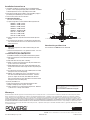
Installation Instructions n
INLET
TO BOILER
CHECK VALVE
BALL VALVE
TEMPERATURE/PRESSURE GAUGE
ABV
CHECK VALVE
TO VALVE
USA: Phone: 1.800.669.5430 • Fax 1.847. 229. 0526 • www.powerscontrols.com
Canada: Phone: 1.888.208.8927 • Fax 1.888.479.2887 • www.powerscontrols.ca
IS-P-Recirculating Loop 1330 EDP# 6511213 © 2013 Powers
A Watts Water Technologies Company
Warranty n
The Seller warrants that the equipment manufactured by it and covered by this order or contract is free from defects in material and workmanship and, without
charge, equipment found to be defective in material or workmanship will be repaired, or at Seller’s option replaced F.O.B. original point of shipment, if written
notice of failure is received by Seller within one (1) year after date of shipment (unless specifically noted elsewhere), provided said equipment has been properly
installed, operated in accordance with the Seller’s instructions, and provided such defects are not due to abuse or decomposition by chemical or galvanic action.
THIS EXPRESS WARRANTY IS IN LIEU OF AND EXCLUDES ALL OTHER WARRANTIES, GUARANTEES, OR REPRESENTATIONS, EXPRESS OF IMPLIED. THERE ARE
NO IMPLIED WARRANTIES OF MERCHANTABILITY OR OF FITNESS FOR A PARTICULAR PURPOSE. The Seller assumes no responsibility for repairs made on the
Seller’s equipment unless done by the Seller’s authorized personnel, or by written authority from the Seller. The Seller makes no guarantee with respect to material
not manufactured by it.
See attached IS-P-LFMM430 and IS-P-LFSH1430.
Valve Servicing and Part List n
WARNING: This product contains chemicals known to the
State of California to cause cancer and birth defects or
other reproductive harm.
For more information: www.watts.com/prop65
NOTICE
-
 1
1
-
 2
2


Watts HydroGuard Water Tempering Installation guide
- Type
- Installation guide
Ask a question and I''ll find the answer in the document
Finding information in a document is now easier with AI
Related papers
-
Powers Single Valve tation™ Supply Fixture Installation guide
-
Powers Process Controls 6550049 Installation guide
-
Powers HydroGuard XP LFSH1430 Installation guide
-
-
-
Powers HydroGuard XP LFSH1434 Quad Valve Installation guide
-
Powers HydroGuard XP LFSH1430 HiLo Installation guide
-
 Powers Process Controls ETV200 Exposed Installation guide
-
Powers HydroGuard ES150 Installation guide
-
Watts LFN170M3 1 1/2 Installation guide

Other documents
-
Ransomes 67923, 67924, 67938, 67955, 67956, 67957 User manual
-
3M Aqua-Pure™ SSEPE Series Whole House Water Filtration Housings - Large Diameter Operating instructions
-
 Proteus Industries 8000 Series Technical Reference Manual
-
-
Fill-rite FR1219G User manual
-
Stanley Black & Decker GT18B01 User manual
-
Hypro 1502, 1700, 4001, 4101, 6500, 7560 and 7700 Roller Pumps Owner's manual
-
Hypro 9306 Series Cast Iron & Stainless Steel Centrifugal Pumps Owner's manual
-
Everpure QC7I Twin - MH User manual
-
