Page is loading ...

1
ENGLISH
ESPAÑOL
FRANÇAIS
DURABILITY / DURABILIDAD / DURABILITÉ
Drop Protection
Protección ante caídas
Protection contre les chutes
9.8 ft.
(3 m)
Safety Rating
Clasificación de seguridad
Cote de sécurité
CAT IV
1000V
Symbols on tester / Símbolos del probador / Symboles sur le testeur
Warning – Risk of electric shock / Advertencia: riesgo de choque eléctrico / Avertissement – Risque
d'électrocution
Risk of danger. Important information: It is important that users of this tester read, understand, and follow all
warnings, cautions, safety information, and instructions in this manual before operating or servicing this tester.
Failure to follow instructions could result in death or serious injury.
Riesgo de peligro. Información importante: Es importante que el usuario de este probador lea,
comprenda y respete todas las advertencias, precauciones, instrucciones e información de seguridad
incluidas en este manual, antes de poner en funcionamiento el probador o de realizarle servicios de
mantenimiento. No seguir estas instrucciones puede dar lugar a lesiones graves o mortales.
Risque de danger. Information importante: Il est important que les utilisateurs de ce testeur lisent,
comprennent et suivent tous les avertissements, mises en garde, information de sécurité et instructions
donnés dans le présent guide avant de faire fonctionner ou de réparer ce testeur. Le non-respect pourrait
entraîner des blessures graves, voire la mort.
Double insulated / Doble aislamiento / Double isolation
Read instructions / Lea las instrucciones / Lire les instructions
This product has been independently tested by Intertek and meets applicable published standards.
Este producto ha sido probado de manera independiente por Intertek y cumple con las normas
publicadas vigentes.
Ce produit a été testé de manière indépendante par Intertek et répond aux exigences des normes applicables.
CAT
IV
For measurements performed at the source of low-voltage installation and outside lines.
Para mediciones realizadas en la fuente de la instalación de bajo voltaje y líneas externas.
Pour des mesures prises à la source d’une installation à faible tension et des lignes extérieures.
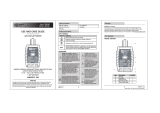
NCVT-5A
FIG. 1
INSTRUCTIONS – Dual-range Non-Contact Voltage Tester with Laser Pointer (English: page 2)
INSTRUCCIONES – Probador de voltaje sin contacto de rango dual con puntero láser (Español: página 3)
INSTRUCTIONS – Testeur de tension sans contact à double plage avec pointeur laser (Français : page 4)
6
4
5
1
2
7
9
8
10
3
1.
NCV Power On/Off Button
2.
Laser Power On/Off Button
3.
Power On/Mode LEDs
4.
Voltage Detection LEDs (Inside Tip)
5.
Non-Contact Tip
6.
Laser Aperture
7.
Pocket Clip
8.
O-ring Seal
9.
Battery Cap
10.
2x AAA Batteries (Included)
NOTE: There are no user-serviceable parts inside tester.
1.
Botón de encendido y apagado "NCV"
2.
Botón de encendido y apagado del láser
3.
LED de encendido/modo
4.
LED de detección de voltaje (en el interior de la punta)
5.
Punta para detección y medición sin contacto
6.
Apertura del láser
7.
Clip de bolsillo
8.
Junta tórica
9.
Tapa del compartimento de baterías
10.
2baterías AAA (incluidas)
NOTA: El probador no contiene en su interior piezas que el
usuario pueda reparar.
1.
Bouton marche/arrêt NCV (test de tension sans contact)
2.
Bouton marche/arrêt du pointeur laser
3.
VoyantsDEL de marche/mode
4.
VoyantsDEL de détection de tension (dans la pointe)
5.
Pointe sans contact
6.
Ouverture du laser
7.
Agrafe pour poche
8.
Joint torique
9.
Couvercle de piles
10.
2pilesAAA (comprises)
REMARQUE: Ce testeur ne contient aucune pièce réparable
par l’utilisateur.
• Detects AC voltage from 12 to 1000V with visual & audible indicators
• Two detection ranges: 70 to 1000V and 12 to 1000V
• Bright integrated laser pointer
• Detecta voltaje CA de 12V a 1000V mediante indicadores visuales y audibles
• Dos rangos de detección: 70V a 1000V y 12V a 1000V
• Puntero láser integrado, con haz de luz brillante
• Détecte la présence d’une tension allant de 12 à 1000Vc.a. et la signale au moyen
d’indicateurs visuels et sonores
• Deux plages de détection: 70 à 1000V et 12 à 1000V
• Pointeur laser lumineux intégré

2
ENGLISH
WARNINGS
To ensure safe operation and service of the tester, follow these
instructions. Failure to observe these warnings can result in severe
injury or death.
• LASER RADIATION, Class IIIa laser. DO NOT direct laser beam into eyes, DO NOT
stare into the beam, or DO NOT view directly with optical instruments as this can cause
severe and permanent eye damage.
• Risk of electric shock and burn. Contact with live circuits could result in death or
serious injury.
• Use caution with voltages above 25V AC as a shock hazard may exist.
• A blinking LED or a steadily illuminated LED in the tip and audible beeps indicate
presence of voltage. If no indication, voltage could still be present.
• Before and after each use, verify operation by testing a known working circuit that is
within the rating of this unit.
• Never assume neutral or ground wires are de-energized. Neutrals in multi-wire branch
circuits may be energized when disconnected and must be retested before handling.
• The tester WILL NOT detect voltage if:
• The wire is shielded.
• The operator is not grounded or is otherwise isolated from an effective earth ground.
• The voltage is DC.
• The tester MAY NOT detect voltage if:
• The user is not holding the tester.
• The user is insulated from the tester with a glove or other materials.
• The wire is partially buried or in a grounded metal conduit.
• The tester is at a distance from the voltage source.
• The field created by the voltage source is being blocked, dampened, or otherwise
interfered with.
• The frequency of the voltage is not a perfect sine wave between 50 and 500Hz.
• The tester is outside of operating conditions (listed in Specifications section).
• Operation may be affected by differences in socket design and insulation thickness
and type.
• In bright light conditions, the LED visual indicators will be less visible.
• When powered-ON, one of the “power-ON” LED’s will be illuminated.
DO NOT USE
TESTER UNLESS ONE OF THE “POWER-ON” LEDs IS ILLUMINATED.
• Do not use if tester appears damaged or is not operating properly. If in doubt, replace
the tester.
• Do not apply more than the rated voltage as marked on the tester (1000V).
• Detection above 70V AC in Mode 1, or above 12V AC in Mode 2 is specified under
"normal" conditions as detailed below. The tester may detect at a different threshold at
different conditions, or may not detect at all unless:
• The tip of the tester is within 0.25" (6 mm) of an AC voltage source radiating unimpeded.
• The user is holding the body of the tester with his or her bare hand.
• The user is standing on or connected to earth ground.
• The air humidity is nominal (50% relative humidity – non-condensing).
• The tester is held still.
• Always wear approved eye protection.
• Comply with local and national safety requirements.
• If this product is used in a manner not specified by the manufacturer, protection
provided by the product may be affected.
OPERATING INSTRUCTIONS
SELECTING VOLTAGE TESTING MODE
NCVT5 can detect voltage in two distinct modes, defined by the
voltage ranges to which the tester is sensitive. Mode 1 detects 70 to
1000V AC, Mode 2 detects 12 to 1000V AC.
With the tester powered-
ON, successive presses of the NCV Power-ON button
1
will switch
the tester between modes 1 and 2. The Power-ON indicator LED’s
3
will indicate the currently active mode.
The tester will power-ON in the
mode that was most recently used.
OPERATING INSTRUCTIONS
CHECKING FOR THE PRESENCE OF AC VOLTAGE
1. Prior to use, test on a known live circuit to verify tester
functionality.
2. Place tip of the tester
5
near AC voltage. If voltage is present,
the unit will emit audible beeps and the LEDs in the tip
4
will
illuminate:
Mode Power-On
LED Color
12 to 70V AC >70 to 1000V AC
Mode 1
70 – 1000V
Range
Red
No illumination, no
sound
Red LED in tip
4
illuminated, continuous
audible beep
Mode 2
12 – 1000V
Range
Blue
Blue LED in tip
4
blinking, pulsing
audible beep
Red LED in tip
4
illuminated, continuous
audible beep
NOTE: In Mode 2, the tester is more sensitive to high voltage sources
and electrically noisy environments. It is recommended to set the
tester to operate in Mode 1 when expected voltages are above 70V AC.
SILENT OPERATION
To activate silent operation, power-ON by pressing and holding the
NCV Power-ON button
1
for more than 2 seconds. Power-ON in this
manner each time silent operation is desired.
CLEANING
Be sure tester is turned off and wipe with a clean, dry lint-free
cloth.
Do not use abrasive cleaners or solvents.
STORAGE
Remove the batteries when not in use for a prolonged period
of time. Do not expose to high temperatures or humidity. After
a period of storage in extreme conditions exceeding the limits
mentioned in the General Specifications section, allow the tester to
return to normal operating conditions before using.
DISPOSAL / RECYCLE
Do not place equipment and its accessories in the trash.
Items must be properly disposed of in accordance with local
regulations. Please see www.epa.gov or www.erecycle.org
for additional information.
CUSTOMER SERVICE
KLEIN TOOLS, INC.
450 Bond Street, Lincolnshire, IL 60069
1-877-553-4676
www.kleintools.com
MAINTENANCE
BATTERY REPLACEMENT
If activating the laser pointer results in a blinking red LED
3
,
the battery
level is too low to operate the laser, but the NCVT may still be used. If
attempts to use either the NCVT or the Laser Pointer results in a blinking
blue LED
3
, the batteries must be replaced.
1. Unscrew the battery cap
9
and remove/recycle spent batteries.
2. Install two new AAA batteries. Note proper polarity.
3. Screw battery cap tightly to ensure a tight seal with the O-Ring
8
.
FUNCTION BUTTONS (FIG. 1)
NCV POWER ON/OFF BUTTON
1
To activate the Non-Contact Voltage Testing feature, press and
release the NCV Power-ON button
1
. The tester will emit a
single beep and one of the Power ON LED’s
3
will illuminate
3
indicating which NCVT mode is active (see OPERATING
INSTRUCTIONS). To power-OFF the tester, press and hold the
NCV button.
NOTE: The tester will automatically power-OFF following 4 minutes
of inactivity to conserve battery life.
LASER ON/OFF BUTTON
2
Press and hold the Laser Power Button
2
to activate the laser
pointer. Release the button to deactivate the laser.
WARNING: LASER RADIATION. DO NOT do any of the
following, as severe and permanent eye damage could result:
•
DO NOT direct laser beam into eyes.
•
DO NOT stare into the beam.
•
DO NOT view directly with optical instruments.
CAUTION
• DO NOT attempt to repair this tester. It contains no serviceable parts.
• DO NOT expose tester to extremes in temperature or high humidity.
GENERAL SPECIFICATIONS
The Klein Tools NCVT-5 is a dual-range non-contact voltage tester
(NCVT) with laser pointer. It can be set to detect voltage from 70 to
1000V AC (Mode 1) or from 12 to 1000V AC (Mode 2). The laser
pointer can function independent of or simultaneously with the NCVT.
• Measurement Range: Mode 1: 70 to 1000V AC
Mode 2: 12 to 1000V AC
• Frequency Range: 50 to 500 Hz
• Laser: Class IIIa, 630 to 670nm, Max. Power <5mW
• Batteries: 2x AAA 1.5V Alkaline
• Operating and Storage Altitude: Up to 6562 ft. (2000 m)
• Operating and Storage Temp: 14° to 122°F (-10° to 50°C)
• Relative Humidity: <95% non-condensing
• Dimensions: 6.0" x 0.96" x 1.16" (152 x 24 x 29 mm)
• Weight: 2.5 oz. (72 g) including batteries
• Pollution degree: 2
• Safety Rating: CAT IV 1000V AC
• Drop Protection: 9.8 ft. (3 m)
• Standards: Conforms to UL STD. 61010-1, 61010-2-030
Certied to
CSA STD. C22.2 No. 61010-1, 61010-2-030
• Complies with: 21 CFR 1040.10 and 1040.11 except for deviations
pursuant to laser notice No. 50, dated June 24, 2007.
Specifications subject to change.

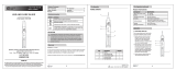
Indicator / Indicador / Voyant Fault / Falla / Anomalie Explanation / Explicación / Explication
Open Ground
Conexión a tierra abierta
Mise à la terre non connectée
Ground contact is not connected
El contacto a tierra no está conectado
Le contact de mise à la terre n’est pas connecté
Open Neutral
Neutro abierto
Neutre ouvert
Neutral contact is not connected
El contacto neutro no está conectado
Le contact neutre n’est pas connecté
Open Hot
Vivo abierto
Phase ouverte
Hot contact is not connected
El contacto vivo no está conectado
Le contact de phase n’est pas connecté
Hot/Ground Reversed
Vivo/Tierra invertidos
Phase/mise à la terre inversées
Hot and ground connections are reversed
Las conexiones viva y de tierra están invertidas
Les connexions de phase et de mise à la terre sont inversées
Hot/Neutral Reversed
Vivo/Neutro invertidos
Phase/neutre inversés
Hot and neutral connections are reversed
Las conexiones viva y neutra están invertidas
Les connexions de phase et de neutre sont inversées
Correct
Correcto
Correct
Receptacle is wired correctly
El receptáculo está cableado correctamente
La prise est câblée correctement
Indicator Not Illuminated
Indicador no iluminado
Voyant éteint
FIG. 1
Indicator Illuminated
Indicador iluminado
Voyant allumé
ENGLISH
GENERAL SPECIFICATIONS
Relative Humidity: < 85% non-condensing
Nominal Power: 0.3W
Operating Temperature: 32° to 140°F (0° to 40°C) Standards:
Conforms To UL Std 61010-1,
61010-2-030,1436
Certified To CSA Std C22.2 #61010-1,
61010-2-030,160
Storage Temperature: 14° to 122°F (-10°C to 50°C)
Operating Altitude: Up to 6562 ft. (2000 m)
Weight: 1.2 oz. (33 g)
Nominal Voltage: 110 - 125V AC at 50/60Hz in 3-wire outlet
Mains supply voltage uctuations: ±10% Drop Protection: 6.6 ft. (2 m)
Pollution Degree: 2 Safety Rating: CAT II 300V
WARNINGS
Read, understand, and follow all warnings and instructions before operating testers. Failure to follow
instructions could result in death or serious injury. Before each use, verify tester operation by testing on
a known live and correctly wired receptacle. Do not use if the tester appears damaged in any way. The
tester is intended for indoor use only. Other equipment or devices attached to the circuit being tested
could interfere with the tester, clear the circuit before testing. This tester only detects common wiring
problems. Always consult a qualified electrician to resolve wiring problems.
WIRING CONFIGURATION TESTING
Conditions indicated: wiring correct,
open ground, reverse polarity, open hot,
open neutral and hot/ground reversed.
Conditions NOT indicated: quality
of ground, multiple hot wires,
combinations of defects, reversal of
grounded and grounding conductors.
All appliances or equipment on
the circuit being tested should be
unplugged to help reduce the possibility
of erroneous readings.
STANDARD RECEPTACLES
1. Verify tester operation by testing
on a known live and correctly wired
receptacle.
2. Plug tester into receptacle.
3. Compare the illuminated lights on
the tester to the key code printed on
the tester.
4. If the tester indicates that the
receptacle is not wired correctly,
consult a qualified electrician.
GFCI RECEPTACLES
1. Check the GFCI receptacle user manual for information
on how the specific receptacle operates prior to using
this tester.
2. Insert the tester into
the receptacle under test to check
for correct wiring (See FIG. 1). Lights on the tester
should illuminate.
3. Press the "TEST" button on the GFCI receptacle.
Did the
GFCI trip and the lights on the tester go dark?
YES:
Reset the GFCI by pressing the reset button.
Proceed to step 4.
NO:
The GFCI is not operating properly or the
receptacle is miswired. Consult a qualified electrician.
4. Press and hold the test button on the tester for 7 seconds.
Did the GFCI trip and the lights on the tester go dark?
YES:
Reset the GFCI by pressing the reset button.
The GFCI appears to be operating properly.
NO:
The GFCI is not operating properly or the
receptacle is miswired. Consult a qualified electrician.
CLEANING
Wipe with a clean, dry
lint-free cloth.
Do not
use abrasive cleaners
or solvents.
DISPOSAL / RECYCLE
Do not place equipment and its accessories in the trash. Items
must be properly disposed of in accordance with local regulations.
Please see www.epa.gov or www.erecycle.org for additional
information.
5001748
ESPAÑOL
ESPECIFICACIONES GENERALES
Humedad relativa: <85% sin condensación
Potencia nominal: 0,3W
Temperatura de
operaón:
32°F a 140°F
(0°C a 40°C)
Temperatura de
almacenamiento:
14°F a 122°F
(-10°C a 50°C)
Altitud de
funcionamiento:
Hasta 6562pies
(2000m)
Normas: Cumple con la norma
UL Std
61010-1, 61010-2-030,1436
Certificado según la norma
CSA Std C22.2 #61010-1,
61010-2-030,160
Peso: 1,2 oz (33 g)
Voltaje nominal: 110VCA - 125VCA a 50Hz/60Hz en tomacorriente de 3alambres
Fluctuaciones de voltaje de suministro de redes: ±10 %
Protección ante caídas: 6,6pies (2m)
Grado de contaminación: 2
Clasicación de seguridad: CAT II 300V
ADVERTENCIAS
Antes de utilizar los probadores, lea, comprenda y respete todas las advertencias e instrucciones. No
seguir estas instrucciones puede dar lugar a lesiones graves o mortales. Antes de cada uso, verifique el
funcionamiento del probador realizando una prueba en un receptáculo con corriente conocida y correctamente
cableado. No utilice el probador si está dañado. El probador está diseñado solo para uso en ambientes interiores.
Es posible que otros equipos o dispositivos conectados al circuito sometido a prueba causen interferencia con
el probador. Despeje el circuito antes de realizar la prueba. Este probador solo detecta problemas de cableado
comunes. Siempre consulte a un electricista calificado para solucionar problemas de cableado.
PRUEBAS DE CONFIGURACIÓN DE CABLEADO
Condiciones indicadas por el probador:
cableado correcto, puesta a tierra abierta,
polaridad inversa, vivo abierto, neutro abierto
yvivo/tierra invertidos.
Condiciones NO indicadas por el probador:
calidad de tierra, múltiples cables vivos,
combinaciones de defectos, inversión de
conductor conectado a tierra y conductor de
conexión a tierra.
Se deben desenchufar todos los
electrodomésticos y equipos conectados al
circuito sometido a prueba para ayudar a
reducir la posibilidad de que se produzcan
lecturas erróneas.
RECEPTÁCULOS ESTÁNDAR
1. Compruebe el funcionamiento del probador
realizando una prueba en un receptáculo con
corriente conocida y correctamente cableado.
2. Enchufe el probador en el receptáculo.
3. Compare las luces encendidas en el
probador con el código de colores impreso
en el probador.
4. Si el probador indica que el receptáculo no
está correctamente cableado, comuníquese
con un electricista calificado.
RECEPTÁCULOS GFCI
1. Antes de usar este probador, lea el manual
del usuario del receptáculo GFCI para obtener
información sobre su funcionamiento.
2. Inserte el probador en el receptáculo sometido
a prueba para verificar si el cableado es
correcto. (Consulte la FIG. 1). Las luces del
probador deben encenderse.
3. Presione el botón "TEST" ("PROBAR") en el
receptáculo GFCI.
¿Se accionó el GFCI y se
oscurecieron las luces del probador?
SÍ:
Reinicie el GFCI presionando el botón
dereinicialización. Siga con el paso 4.
NO:
El GFCI no funciona correctamente o
el receptáculo tiene errores de cableado.
Comuníquese con un electricista calificado.
4. Mantenga presionado el botón de prueba en el
probador durante 7segundos.
¿Se accionó el
GFCI y se oscurecieron las luces del probador?
SÍ:
Reinicie el GFCI presionando el botón de
reinicialización. Parece que el GFCI funciona
correctamente.
NO:
El GFCI no funciona correctamente o
el receptáculo tiene errores de cableado.
Comuníquese con un electricista calificado.
LIMPIEZA
Límpielo con un paño limpio,
seco, que no deje pelusas.
No utilice solventes ni
limpiadores abrasivos.
ELIMINACIÓN/RECICLAJE
No arroje el equipo ni sus accesorios a la basura.
Los elementos se deben desechar correctamente de
acuerdo con las regulaciones locales. Para obtener más
información, consulte www.epa.gov o www.erecycle.org.
5001748
FRANÇAIS
CARACTÉRISTIQUES GÉNÉRALES
Humidité relative: < 85% (sans condensation)
Puissance nominale: 0,3W
Température de
fonctionnement:
0°C à 40°C
(32°F à 140°F)
Température
d’entreposage:
-10°C à 50°C
(14°F à 122°F)
Altitude de
fonctionnement:
Jusqu'à 2000m
(6562pi)
Certication: Conforme à la norme
UL Std 61010-1,
61010-2-030,1436
Certifié conforme à la
norme CSA Std C22.2
#61010-1, 61010-2-030,160
Poids: 33g (1,2oz)
Tension nominale: 110 - 125V c.a. à 50/60Hz dans une prise à trois fils
Fluctuations de tension d’alimentation du réseau : ± 10 %
Protection contre les chutes: 2m (6,6pi)
Niveau de pollution: 2 Cote de sécurité: CATII300V
AVERTISSEMENTS
Veuillez lire, comprendre et tenir compte de tous les avertissements et de toutes les directives avant
d’utiliser un testeur. Le non-respect pourrait entraîner des blessures graves, voire la mort. Avant chaque
utilisation, vérifiez le fonctionnement de l'appareil en effectuant un test sur une prise dont le fonctionnement
est connu et dont le câblage est correct. N'utilisez pas l'appareil s'il semble avoir été endommagé de
quelque manière que ce soit. Cet appareil est destiné à une utilisation à l'intérieur seulement. D’autres
équipements ou appareils branchés au circuit vérifié peuvent interférer avec l’appareil; libérez le circuit
avant de débuter la vérification. Ce testeur ne détecte que les problèmes de câblage les plus fréquents.
Communiquez toujours avec un électricien qualifié pour résoudre les problèmes de câblage.
VÉRIFICATION DE LA CONFIGURATION DE CÂBLAGE
Conditions indiquées: câblage adéquat,
mise à la terre ouverte, polarité inversée,
phase ouverte, neutre ouvert et phase/
mise à la terre inversées.
Conditions NON indiquées: qualité de
la mise à la terre, fils de phase multiples,
combinaisons de défauts, inversement
des conducteurs mis à terre et des
conducteurs de mise à la terre.
Tous les électroménagers et l’équipement
électrique branchés sur le circuit vérifié
doivent être débranchés pour réduire le
risque de lecture erronée.
PRISES STANDARD
1. Vérifiez le fonctionnement de
l’appareil en effectuant un test sur
une prise dont le fonctionnement est
connu et dont le câblage est correct.
2. Branchez l’appareil dans la prise.
3. Comparez les voyants allumés sur le
testeur au code de référence imprimé
sur celui-ci.
4. Si le testeur indique que le câblage
de la prise est incorrect, consultez
unélectricien qualifié.
PRISES GFCI
1. Consultez le manuel de l’utilisateur de la prise GFCI pour
connaître le fonctionnement de la priseavant d’utiliser ce testeur.
2. Insérez le testeur dans la prise pour vérifier si le
câblage est adéquat (voir la FIG.1). Les voyants sur
letesteur devraient s’allumer.
3. Appuyez sur le bouton «TEST» de la prise GFCI.
Laprise GFCI s’est-elle déclenchée et les voyants
sur le testeur se sont-ils éteints?
OUI:
Réinitialisez la prise GFCI en appuyant sur le
bouton de réenclenchement sur celle-ci. Passez à
l’étape4.
NON:
La prise GFCI ne fonctionne pas
correctement ou le câblage n’est pas adéquat.
Consultez un électricien qualifié.
4. Appuyez sur le bouton de test du testeur pendant
7secondes.
La prise GFCI s’est-elle déclenchée
et
lesvoyants sur le testeur se sont-ils éteints?
OUI:
Réinitialisez la prise GFCI en appuyant sur le
bouton de réenclenchement sur celle-ci. La prise
GFCI semble fonctionner correctement.
NON:
La prise GFCI ne fonctionne pas correctement
ou le câblage n’est pas adéquat. Consultez un
électricien qualifié.
NETTOYAGE
Essuyez l’appareil avec un linge
propre, sec et non pelucheux.
N’utilisez pas de nettoyant
abrasif ou de solvant.
MISE AU REBUT/RECYCLAGE
Ne pas mettre l’appareil et ses accessoires au rebut.
Ces articles doivent être éliminés conformément aux
règlements locaux. Pour de plus amples renseignements,
consultez les sites www.epa.gov ou www.erecycle.org.
5001748
Hot (Black)
Vivo (negro)
Phase (noir)
Neutral (White)
Neutro (blanco)
Neutre (blanc)
Ground (Green)
Tierra (verde)
Mise à la terre (vert)
RT210
INSTRUCTIONS – GFCI Receptacle Tester (English: page 2)
INSTRUCCIONES – Probador de tomacorrientes con interruptor GFCI (Español: página 3)
INSTRUCTIONS – Véricateur de prises GFCI (Français : page 4)
• Designed to detect the most common wiring problems in standard and GFCI receptacles: Open
ground, reverse polarity, open hot, open neutral, hot/ground reversed
• Diseñado para detectar los problemas de cableado más comunes en receptáculos estándar y GFCI:
puesta a tierra abierta, polaridad inversa, vivo abierto, neutro abierto y vivo/tierra invertidos
• Conçu pour détecter les problèmes de câblage les plus fréquents dans des prises standard et GFCI:
mise à la terre ouverte, polarité inversée, phase ouverte, neutre ouvert, phase/mise à laterre inversées
Warranty / Garantía / Garantie :
www.kleintools.com/warranty
/