Page is loading ...

1
WARNING: Because of the possible danger to person(s) or
property from accidents which may result from the improper
use of products, it is important that correct procedures be
followed. Products must be used in accordance with the
engineering information specified in the catalog. Proper
installation, maintenance and operation procedures must
be observed. The instructions in the instruction manuals
must be followed. Inspections should be made as necessary
to assure safe operation under prevailing conditions. Proper
guards and other suitable safety devices or procedures as
may be desirable or as may be specified in safety codes
should be provided, and are neither provided by ABB nor
are the responsibility of ABB. This unit and its associated
equipment must be installed, adjusted and maintained by
qualified personnel who are familiar with the construction
and operation of all equipment in the system and the
potential hazards involved. When risk to persons or property
may be involved, a holding device must be an integral part
of the driven equipment beyond the speed reducer output
shaft.
WARNING: To ensure the drive is not unexpectedly
started, turn off and lock-out or tag power source before
proceeding. Failure to observe these precautions could
result in bodily injury.
WARNING: All products over 25 kg (55 lbs) are noted on the
shipping package. Proper lifting practices are required for
these products.
Instruction Manual for 70C, 70D 75C and 75D
FLEXIDYNE
®
Couplings and Drives
These instructions must be read thoroughly before installation or operation. This instruction manual was accurate at the time of
printing. Please see baldor.com for updated instruction manuals.
Note! The manufacturer of these products, Baldor Electric Company, became ABB Motors and Mechanical Inc. on
March 1, 2018. Nameplates, Declaration of Conformity and other collateral material may contain the company name of
Baldor Electric Company and the brand names of Baldor-Dodge and Baldor-Reliance until such time as all materials have
been updated to reflect our new corporate identity.
DESCRIPTION
FLEXIDYNE dry uid couplings and drives are unique concepts
to provide soft start and momentary overload protection for all
types of driven equipment. Standard EMAB motors with RPM
base speeds of 1750, 1160 or 860 are commonly used with a
FLEXIDYNE coupling or drive, yet other available power sources
may be used with the FLEXIDYNE mechanism.
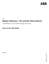
The dry "uid" in the FLEXIDYNE housing is heat treated steel
shot. A measured amount, referred to as ow charge, is added
into a housing which has been keyed to the motor shaft. When
the motor is started, centrifugal force throws the ow charge to
the perimeter of the housing, packs it between the housing and
the rotor which in turn transmits power to the load.
After the starting period of slippage between housing and rotor
the two become locked together and achieve full load speed,
operating without slip and with 100% efciency.
Consequently, the motor accelerates instantly to base speed,
while the load starts gradually and smoothly.
Housing
Flow Charge
Output
Shaft
Rotor
Flexible
Coupling
Motor
Shaft
Rotor
Output
Sheave
Motor
Shaft
Flow Charge
Housing
Coupling Drives
Figure 1 - Housing cross section
INSTALLATION
COUPLINGS:
Install coupling ange on motor shaft and drive housing
mechanism on driven shaft in accordance with the instruction
manual for the Taper-Lock® bushings.
NOTE: The coupling flange must be mounted on motor
shaft (not driven shaft) to allow proper operation of the
FLEXIDYNE coupling.
Shaft ends must not protrude beyond bushing ends. Install
coupling disc over pins on drive housing mechanism. Position
the motor and the driven unit so that the spacer buttons on the
coupling disc slightly contact the coupling ange. Reference
Dimension A on Parts Replacement Drawing.
(A = 5/8” on size 70C; A = 3/4” on size 75C)
For longest FLEXIDYNE coupling life, it is always desirable to align
coupling as accurately as possible at initial installation. Check
alignment by laying a straight edge across the coupling ange
and drive housing at several points around the circumference.
NOTE: Driven shaft must not touch housing hub.

2
DRIVES:
Install the FLEXIDYNE special bolt-on sheave on the driven hub.
Use screws and lock washers provided with the FLEXIDYNE
drive. Torque screws to 160 inch-pounds.
Stake motor shaft key in place and slide FLEXIDYNE drive onto
the motor shaft, with collar as close to the motor as possible.
Tighten key set screw securely against motor shaft key. Tighten
shaft set screw securely against motor shaft.
NOTE: The sheave is the output of the FLEXIDYNE drive, do
not input power to the FLEXIDYNE drive through the sheave.
In other words, do not mount the FLEXIDYNE drive on the
driven shaft.
START-UP
1. Remove the ller plug and install the proper amount of
ow charge specied in Table 1. Replace and tighten ller
plug, making sure that no ow charge is trapped in threads.
Torque ller plug to 35 inch-pounds.
2. Attach AC ammeter (conventional clamp-on or equivalent) to
one line of the AC motor. Set range to cover 200% of motor
nameplate current.
3. Note the maximum allowable acceleration time as stated in
Tables 1 and 2.
Note: Table 2 lists starting time capacity for starting cycles
occurring more than once every 2 hours.
4. Push start button. Observe motor current during load
acceleration and number of seconds required to reach full
speed (Fig. 2).
Increase amount of ow charge if:
A. Acceleration time reaches maximum allowable before
load is up to speed. Turn off power immediately if this time
is reached.
B. Acceleration amperage is below motor nameplate.
Decrease amount of ow charge if:
A. Acceleration time is less than 1-1/2 seconds.
B. Acceleration amperage is above 200% of motor nameplate.
Once satisfactory operation has been obtained, record the
following for future reference:
1. The amount of ow charge
2. Starting current
3. Acceleration Time
WARNING: The rotor must slip during acceleration to allow
flow charge to become evenly distributed in the FLEXIDYNE
housing. Therefore, DO NOT ALLOW FLEXIDYNE
MECHANISM TO RUN "FREE" (that is, without a load on
the driven end), otherwise an out-of-balance condition may
result, damaging mechanism and attached equipment.
Seconds from Start
Acceleration Amps
Lock-In
400
300
200
100
10
8
6
4
2
In-rush Amps
Running
Amps
%
Nameplate
Motor
Current
Figure 2 - Typical Motor Current vs. Time
OPER ATION
The amount of ow charge in the housing determines the
acceleration time for a given load. Slower acceleration times will
occur when less ow charge is used and faster acceleration,
from stop to full speed, will be observed with greater amounts
of ow charge.
The FLEXIDYNE mechanism should start the load smoothly and
without delay, provided the proper amount of ow charge has
been used. Should the acceleration time exceed the maximum
allowable in Table 1, shut off power to the FLEXIDYNE mechanism
immediately. Allow the FLEXIDYNE mechanism to cool, then
add small amounts of ow charge until proper acceleration is
observed.
Vibration is an indication of accelerating too rapidly and not
allowing ow charge to become evenly distributed in the
FLEXIDYNE housing. This can be corrected by removing small
amounts of ow charge until vibration subsides. Other causes of
vibration are: undersize shafting, unit not installed far enough on
shaft or worn bore in the unit.
Slippage — The FLEXIDYNE mechanism can, without slipping,
transmit overloads up to 130% of its pre-set starting torque.
Should this breakaway torque be exceeded, the FLEXIDYNE
mechanism will slip and generate heat (see Overload Protection).
Although slippage usually indicates increased loads, it can also
be caused by worn ow charge or a worn rotor especially if the
FLEXIDYNE mechanism has been in operation for some time.
The necessity to replace either a rotor or ow charge will be
made evident by a loss in power transmitting capacity of the
FLEXIDYNE mechanism.
MAINTENANCE
For average industrial applications involving 3 or 4 starts a day
and of not more than 6 seconds acceleration time each, the ow
charge should be changed every 10,000 hours of operation. For
more severe conditions, visually inspect ow charge at more
frequent intervals; it should be changed when it has deteriorated
to a half powder, half granular condition. See page 8 for ow
charge analysis. Visual inspections should continue until enough
ow charge changes have been made to adequately establish a
schedule for renewing FLEXIDYNE ow charge.
The FLEXIDYNE mechanism has been lubricated at the factory
and no further lubrication is required. Never apply grease, oil or
any other foreign material to the ow charge.

3
THERMAL CAPACITY
Since there is slippage within the ow charge during acceleration,
heat is generated from friction. The thermal capacity of the
FLEXIDYNE mechanism is based on balancing this heat
generated during acceleration against the cooling time between
accelerations. The amount of heat generated is determined
by the amount of horsepower dissipated by slipping and the
duration of each acceleration. If the ow charge weight is light,
the heat generated will not be as great as that which would
be generated with a heavier ow charge, when compared at
the same acceleration time. A longer time between starts will
dissipate more heat; therefore, higher starting horsepowers may
be transmitted, or longer acceleration times may be allowable.
(See Starting Cycle)
Acceleration times shown in Table 1 are for starting frequencies
of one start per hour or less. If starting frequency is more than
once per hour, use acceleration time for actual starting cycle
shown in Table 2.
Acceleration times listed in Tables 1 and 2 are the MAXIMUM
permissible for the various starting frequencies listed. The
MINIMUM acceleration time required for proper FLEXIDYNE
mechanism operation is 1 to 1½ seconds. This is the time
required for the ow charge to be uniformly distributed around
the housing cavity before the unit "locks in". Any acceleration
time between the minimum and maximum listed is acceptable,
although a shorter acceleration time will generally provide longer
wear life. For applications requiring a specic acceleration time
(within these limits) ow charge may be added or removed to
produce the required results.
Stalled — If a jam-up stalls the drive, the motor continues to run
and the FLEXIDYNE mechanism slips. This causes heat to be
generated at twice the rate of normal acceleration. Therefore,
the allowable slipping time, when stalled, is half the allowable
acceleration time given in Table 1.
Starting Cycle is the time from the beginning of one acceleration
to the beginning of the next. Allowable acceleration times in Table
2 are based on the assumption that the FLEXIDYNE mechanism
will be running continuously except for a momentary stop before
the next start. If the stop is more than momentary, decrease the
actual starting cycle by one-half the stopped time before using
Table 2; for example, with a 50 minute actual starting cycle of
which 20 minutes is stopped time, decrease 50 by half of 20 to
give 40 minutes as the starting cycle time to use for Table 2.
Grouped Starts — For several starts grouped together followed
by uninterrupted running, add the acceleration times of all starts
and consider it as the time for one start. The starting cycle would
be the time from the beginning of one group of starts to the
beginning of the next group.

4
Table 1 - Flow Charge Recommendations
Based on % of Starting Torque for 1760 RPM NEMA Design B Motors
Rated
Motor
HP
FLEXIDYNE
Mechanism
Size
100% @ 1760 RPM 125% @ 1750 RPM 150% @ 1740 RPM
Starting
HP
Flow Charge
Max
Time in
Sec.
Starting
HP
Flow Charge
Max
Time in
Sec.
Starting
HP
Flow Charge
Max
Time in
Sec.
Lbs. Oz. Lbs. Oz. Lbs. Oz.
3 70C, 70D 3.0 1 11 150 3.7 1 13 123 4.5 1 14 105
5 70C, 70D 5.0 1 14 94 6.2 2 1 79 7.5 2 4 67
7-1/2 75C, 75D 7.5 1 11 71 9.4 1 14 60 11.2 2 1 54
10 75C, 75D 10.0 1 15 58 12.5 2 3 53 14.9 2 6 48
Rated
Motor
HP
FLEXIDYNE
Mechanism
Size
175% @ 1700 RPM 175% @ 1700 RPM
Starting
HP
Flow Charge Max
Time in
Sec.
Starting
HP
Flow Charge Max
Time in
Sec.
Lbs. Oz. Lbs. Oz.
3 70C, 70D 5.1 2 0 93 5.1 2 0 93
5 70C, 70D 8.5 2 8 60 8.5 2 8 60
7-1/2 75C, 75D 12.7 2 4 52 12.7 2 4 52
10 75C, 75D 17. 0 2 9 43 17.0 2 9 43
Based on % of Starting Torque for 1175 RPM NEMA Design B Motors
Rated
Motor
HP
FLEXIDYNE
Mechanism
Size
100% @ 1175 RPM 125% @ 1160 RPM 150% @ 1150 RPM
Starting
HP
Flow Charge Max
Time in
Sec.
Starting
HP
Flow Charge Max
Time in
Sec.
Starting
HP
Flow Charge Max
Time in
Sec.
Lbs. Oz. Lbs. Oz. Lbs. Oz.
1 70C, 70D 1.0 1 10 500 1.2 1 12 400 1.5 1 14 33.
1-1/2 70C, 70D 1.5 1 13 300 1.9 2 1 260 2.2 2 3 210
2 75C, 75D 2.0 1 10 250 2.5 1 13 190 3.0 2 0 150
3 75C, 75D 3.0 1 15 150 3.7 2 3 125 4.5 2 7 100
Rated
Motor
HP
FLEXIDYNE
Mechanism
Size
175% @ 1130 RPM 200% @ 1100 RPM
Starting
HP
Flow Charge
Max
Time in
Sec.
Starting
HP
Flow Charge
Max
Time in
Sec.
Lbs. Oz. Lbs. Oz.
1 70C, 70D 1.7 2 1 290 1.9 2 4 260
1-1/2 70C, 70D 2.5 2 6 190 2.8 2 9 170
2 75C, 75D 3.4 2 2 135 3.8 2 6 120
3 75C, 75D 5.1 2 10 89 5.7 2 12 82
Based on % of Starting Torque for 875 RPM NEMA Design B Motors
Rated
Motor
HP
FLEXIDYNE
Mechanism
Size
100% @ 875 RPM 125% @ 870 RPM 150% @ 850 RPM
Starting
HP
Flow Charge Max
Time in
Sec.
Starting
HP
Flow Charge Max
Time in
Sec.
Starting
HP
Flow Charge Max
Time in
Sec.
Lbs. Oz. Lbs. Oz. Lbs. Oz.
1/2 70C, 70D .50 1 12 900 .62 1 15 850 .75 2 1 800
3/4 70C, 70D .75 2 0 800 .94 2 3 570 1.1 2 6 500
1 75C, 75D 1.0 1 13 520 1.2 2 0 400 1.5 2 3 330
1-1/2 75C, 75D 1.5 2 2 330 1.9 2 7 300 2.2 2 10 250
Rated
Motor
HP
FLEXIDYNE
Mechanism
Size
175% @ 840 RPM 200% @ 820 RPM
Starting
HP
Flow Charge
Max
Time in
Sec.
Starting
HP
Flow Charge
Max
Time in
Sec.
Lbs. Oz. Lbs. Oz.
1/2 70C, 70D .85 2 4 750 .94 2 6 570
3/4 70C, 70D 1.3 2 8 400 1.4 2 12 350
1 75C, 75D 1.7 2 7 320 1.9 2 8 300
1-1/2 75C, 75D 2.5 2 11 220 2.3 2 12 200

5
Table 2 - Thermal Capacity
Starting
HP
Maximum Allowable Acceleration Time in Seconds
For Standard Motor Speeds of Various Starting Cycles
2 Hours 1 Hour 30 Minutes 15 Minutes
870 116 0 1750 870 116 0 1750 870 116 0 1750 870 116 0 1750
70
.50 900 . . . . . . . . 900 . . . . . . . . 900 . . . . . . . . 800 . . . . . . . .
.75 800 . . . . . . . . 800 . . . . . . . . 800 . . . . . . . . 700 . . . . . . . .
1.0 550 500 . . . . 550 500 . . . . 550 500 . . . . 500 450 . . . .
2.0 . . . . 260 210 . . . . 260 210 . . . . 260 210 . . . . 230 190
2.5 . . . . 190 180 . . . . 190 180 . . . . 190 180 . . . . 165 160
3.0 . . . . 170 150 . . . . 170 150 . . . . 170 150 . . . . 155 140
4.0 . . . . 130 110 . . . . 130 110 . . . . 130 110 . . . . 118 100
6.0 . . . . . . . . 80 . . . . . . . . 80 . . . . . . . . 80 . . . . . . . . 72
8.0 . . . . . . . . 63 . . . . . . . . 63 . . . . . . . . 63 . . . . . . . . 56
10.0 . . . . . . . . 53 . . . . . . . . 53 . . . . . . . . 53 . . . . . . . . 46
Starting
HP
Maximum Allowable Acceleration Time in Seconds
For Standard Motor Speeds of Various Starting Cycles
10 Min 5 Minutes 2 Minutes 1 Minutes
870 116 0 1750 870 116 0 1750 870 116 0 1750 870 116 0 1750
70
.50
500 . . . . . . . . 250 . . . . . . . . 100 . . . . . . . . 50 . . . . . . . .
.75 400 . . . . . . . . 230 . . . . . . . . 100 . . . . . . . . 50 . . . . . . . .
1.0 330 320 . . . . 210 200 . . . . 100 80 . . . . 50 45 . . . .
2.0 . . . . 190 170 . . . . 120 105 . . . . 60 58 . . . . 38 36
2.5 . . . . 143 140 . . . . 88 85 . . . . 49 45 . . . . 33 29
3.0 . . . . 133 120 . . . . 80 74 . . . . 45 39 . . . . 28 25
4.0 . . . . 90 83 . . . . 60 54 . . . . 36 30 . . . . 23 19
6.0 . . . . . . . . 60 . . . . . . . . 38 . . . . . . . . 21 . . . . . . . . 13
8.0 . . . . . . . . 41 . . . . . . . . 29 . . . . . . . . 16 . . . . . . . . 10
10.0 . . . . . . . . 36 . . . . . . . . 23 . . . . . . . . 13 . . . . . . . . 8
Starting
HP
Maximum Allowable Acceleration Time in Seconds
For Standard Motor Speeds of Various Starting Cycles
2 Hours 1 Hour 30 Minutes 15 Minutes
870 116 0 1750 870 116 0 1750 870 116 0 1750 870 116 0 1750
75
1.0 520 . . . . . . . . 520 . . . . . . . . 520 . . . . . . . . 520 . . . . . . . .
2.0 300 250 . . . . 300 250 . . . . 300 250 . . . . 300 220 . . . .
3.0 200 120 . . . . 200 150 . . . . 200 150 . . . . 200 130 . . . .
4.0 . . . . 110 . . . . . . . . 110 . . . . . . . . 110 . . . . . . . . 100 . . . .
5.0 . . . . 90 85 . . . . 90 85 . . . . 90 85 . . . . 85 80
7.0 . . . . 75 73 . . . . 75 73 . . . . 75 73 . . . . 70 68
8.0 . . . . . . . . 70 . . . . . . . . 70 . . . . . . . . 70 . . . . . . . . 64
10.0 . . . . . . . . 58 . . . . . . . . 58 . . . . . . . . 58 . . . . . . . . 53
15.0
. . . . . . . . 48 . . . . . . . . 48 . . . . . . . . 48 . . . . . . . . 43
20.0 . . . . . . . . 40 . . . . . . . . 40 . . . . . . . . 40 . . . . . . . . 35
Starting
HP
Maximum Allowable Acceleration Time in Seconds
For Standard Motor Speeds of Various Starting Cycles
10 Min 5 Minutes 2 Minutes 1 Minutes
870 116 0 1750 870 116 0 1750 870 116 0 1750 870 116 0 1750
75
1.0 420 . . . . . . . . 260 . . . . . . . . 100 . . . . . . . . 50 . . . . . . . .
2.0 210 180 . . . . 130 110 . . . . 80 60 . . . . 40 40 . . . .
3.0 150 110 . . . . 100 65 . . . . 52 40 . . . . 30 22 . . . .
4.0
. . . . 82 . . . . . . . . 50 . . . . . . . . 28 . . . . . . . . 18 . . . .
5.0 . . . . 70 65 . . . . 45 40 . . . . 24 22 . . . . 16 15
7.0 . . . . 60 57 . . . . 38 37 . . . . 21 20 . . . . 14 13
8.0 . . . . . . . . 54 . . . . . . . . 35 . . . . . . . . 18 . . . . . . . . 11
10.0 . . . . . . . . 45 . . . . . . . . 30 . . . . . . . . 16 . . . . . . . . 10
15.0 . . . . . . . . 34 . . . . . . . . 21 . . . . . . . . 11 . . . . . . . . 8
20.0 . . . . . . . . 27 . . . . . . . . 17 . . . . . . . . 8 . . . . . . . . 5

6
REPLACEMENT OF PARTS
COUPLINGS:
Disassembly:
1. Remove drive housing mechanism from driven shaft.
2. Remove ller plug and ow charge from FLEXIDYNE housing.
3. Remove housing screws, housing cover and cover seal.
4. Remove screws that attach driven hub to rotor retainer.
Remove driven hub and rotor.
5. Remove bronze bushing retainer ring and slip bronze
bushing off drive housing.
6. Remove ball bearing snap ring and ball bearing. In removing
ball bearing, place 3 equal length pins in the 3 holes thru
the end of the drive housing and press against the pins. For
sizes 70 and 75 use to 9/64 diameter pins.
7. Remove rotor retainer.
Reassembly:
1. Install new seal felt and housing seal in drive housing.
2. Set rotor retainer in place in drive housing.
3. Press ball bearings onto drive housing. Note: Press against
inner (not outer) race of bearing. Make sure rotor retainer is
not cocked when bearing enters it. Check to see that rotor
retainer rotates freely in housing seal.
4. Install ball bearing retaining ring.
5. Install bronze bushing and snap ring.
6. Install rotor and driven hub. Install and tighten screws.
7. Install cover seal in housing cover and place cover in position
on drive housing. Install and tighten housing screws.
8. Replace ow charge and ller plug per STARTUP.
DRIVES:
Disassembly:
1. Loosen set screws in collar and remove FLEXIDYNE drive
from motor shaft.
2. Remove ller plug and drain ow charge from FLEXIDYNE
housing.
3. Remove sheave from FLEXIDYNE mechanism.
4. Remove housing screws and remove housing cover. Remove
cover seal.
5. Remove collar. Remove the six rotor screws and slide driven
hub off drive hub. Remove rotor.
6. Remove needle bearing snap ring and needle bearing inner
race.
7. Remove the six drive hub screws and remove the drive hub
housing. Remove housing seal.
8. Remove rotor retainer and seal felt.
9. Remove ball bearing snap ring and remove ball bearing.
10. Remove needle bearing and seal from driven hub by placing
a plug in the left hand end (as viewed in the drawing) of
driven hub bore and pressing against the plug.
Reassembly:
1. Press roller bearing into right hand end of driven hub. Make
sure left hand end of bearing is ¼ from left hand end of driven
hub. Roller bearing should be lled with high temperature
roller bearing grease. Tap roller bearing seal into place, ush
with left hand end of driven hub.
2. Install housing seal in drive hub housing and attach drive
hub housing to drive hub with six screws. Install seal felt on
drive hub and rotor retainer in position in drive hub housing,
making sure that housing seal is properly seated in drive hub
housing.
3. Press ball bearing onto drive hub. Press against inner (not
outer) race of bearing. Rotor retainer must not be cocked
when bearing enters it. Check, after pressing by making
certain rotor retainer rotates freely in seal. Install ball bearing
snap ring. Install needle bearing inner race and snap ring on
drive hub.
4. Place rotor in position. Slide driven hub over drive hub.
Install and tighten the six rotor screws.
5. Install cover seal. Install housing cover on drive hub housing
so ller plug hole lines up with relief on the ange of drive
hub housing. Install and tighten housing screws.
6. Install motor shaft collar and ller plug. Place bolt-on sheave
in position and install and tighten six sheave bolts.
Table 3 - Manufacturer’s Part Numbers for Replacement Ball Bearings
FLEXIDYNE
Mechanism
Size
Dodge
Part Number
SKF
Part Number
NEW
DEPARTURE
Part Number
70C & 70D 391200 6010 2RS/ME Z4993L10XIV
75C & 75D 391200 6010 2RS/ME Z4993L10XIV

7
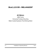
Parts Replacment for 70C, 70D 75C and 75D
FLEXIDYNE® Couplings and Drives
20 12
6
A
DRIVEN
END
MOTOR
END
2
4
8
44
34
24, 25, 2632
36
40
42
50
10
5
30
46
22
2
(Type H)
(Type F)
14, 15
22 20 28, 29 12
30
18
16
10
52
48
49
50 36 32 24, 25, 26
34
44
42
40
14, 15
60,61
28, 29
Reference Name of Part
No.
Required
Part Number
70C 75C 70D 75D
2 Coupling Flange
Type H
Type F
1 008041
008040
008043
008042
. . . .
. . . .
. . . .
. . . .
4
5
6
8
Taper-Lock Bushing w/screws (Motor End)
Taper-Lock Bushing w/screws (Driven End)
POLY-DISC® Coupling Element
Flange Pin
1
1
1
4
1215
1610
008032
409122
1615
1610
008033
409123
. . . .
. . . .
. . . .
. . . .
. . . .
. . . .
. . . .
. . . .
10
12
14
15
16
18
➀
Drive Hub
Drive Hub Housing
Drive Hub Screw
Lockwasher
Drive Hub Collar
Drive Hub Collar Set Screw
Drive Hub Key
1
1
6
6
1
1
305076
305078
415100
419007
......
......
......
305077
305078
415100
419007
......
......
......
➂
305079
417020
419043
305135
➁
......
➃
305079
417020
419043
305135
➁
443390
20
22
24
25
26
28
29
Housing Cover
Housing Seal
Housing Screw
Lockwasher
Hex Nut
Filler Plug
Lockwasher
1
2
6
6
6
1
1
305091
305138
411296
419007
407082
305018
419190
305091
305138
411296
419007
407082
305018
419190
305091
305138
411296
419007
407082
305018
419190
305091
305138
411296
419007
407082
305018
419190
30
32
34
36
Driven Hub
Rotor
Rotor Retainer
Rotor Screw
1
1
1
6
305075
305094
305096
415052
305075
305095
305096
415052
305073
305094
305096
415052
305074
305095
305096
415052
40
42
44
46
48
49
50
52
Ball Bearing
Retaining Ring
Duct Seat
Bronze Bearing
Needle Bearing
Needle Bearing Inner Race
Retaining Ring
Bearing Seal
1
1
1
1
1
1
➅
1
391200
421150
308024
426070
.....
......
421004
.....
391200
421150
308024
426070
.....
......
421004
.....
391200
421150
308024
.....
426022
426039
421145
305139
391200
421150
308024
.....
426022
426039
421145
305139
60
61
Sheave Screw
Lockwasher
4
4
...... ...... 417047 417050
...... ...... 419045 419045
➀ Not shown on parts drawing.
➁ Size 70D × 7/8 – 400062, 2 required; Sizes 70D × 11/8 & 75D × 11/8 – 400054, 1 required & 400058, 1 required; Size 75D × 13/8 – 400054, 2 required.
➂ 305069 required on Size 70D × 7/8; 305070 required on Size 70D × 1-1/8.
➃ 305071 required on Size 75D × 1-1/8; 305072 required on Size 75D × 1-3/8.
➄ 1 required on Size 75D × 1-3/8 only.
➅ 1 required on FLEXIDYNE Coupling units; 2 required on FLEXIDYNE Drive units

—
ABB Motors and Mechanical Inc.
5711 R. S. Boreham Jr. Street
Fort Smith, AR 72901
Ph: 1.479.646.4711
Mechanical Power Transmission Support
Ph: 1.864.297.4800
new.abb.com/mechanical-power-transmission
baldor.com
© ABB Motors and Mechanical Inc.
MN4034 (Replaces 499868)
All Rights Reserved. Printed in USA.
01/20 Printshop 300
*4034-0120*
Flexidyne Mechanism Trouble Analysis
Symptom Cause Cure
Vibration 1. Misalignment
2. Bent shaft
3. Excess ow charge
4. Fused ow charge
5. Improper installation – Output shaft
jammed against housing
1. Realign drive or coupling.
2. Replace or straighten.
3. Remove small amount of ow charge.
4. Correct the overload.
5. Readjust spacing between shafts and
Flexidyne housing.
Erratic Acceleration 1. Breakdown of ow charge
2. Caked ow charge
3. Below minimum amount of ow
charge
1. Replace ow charge.
2. Moist environment – use stainless ow
charge.
3. Add ow charge.
Flexidyne Mechanism Doesn’t Slip 1. Improper installation – Output shaft
jammed against housing
2. Flow charge in bearings – causing
bearing seizure
1. Readjust spacing between shafts and
Flexidyne housing.
2. Replace seals, bearings and
ow charge or replace Flexidyne
mechanism.
Excessive Slippage 1. Not enough ow charge
2. Overload
3. Worn ow charge
4. Worn rotor
1. Add ow charge.
2. Relieve overload
3. Replace ow charge.
4. Replace rotor.
Poor or short ow charge life 1. Excessive slip at start up
2. Excessive inching or jogging of
machine
1. Add ow charge to reduce starting
time.
2. Install time delay in motor control
circuit.
Flexidyne Mechanism Flow Charge Analysis
Condition Cause
1. Red oxide color, granular consistency
2. Red oxide color, powdery consistency, possibly with
powdery akes
3. Black, powdery
4. Red oxide, powdery and chunky
5. Clumping of ow charge
1. Normal after some usage.
2. Worn-out, can cause Flexidyne mechanism damage.
3. Rotor worn, excessive slip and heat.
4. Worn-out and moisture present.
5. Moisture present, use stainless ow charge.
/