Page is loading ...

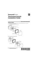
INSTALLATION GUIDE
GUIDE D’INSTALLATION
GUÍA DE INSTALACIÓN
CT230-GA / CT230-GB
LINKED UNIT
UNITÉ ESCLAVE
UNIDAD ENLAZADA
33-00222EFS-04

Need Help?
We are here to help. Call 1-800-468-1502.
Besoin d’aide?
Nous sommes là. Composez le 1 800 468-1502.
¿Asistencia?
Estamos aquí para ayudarlo. Llame al 1 800 468-1502.

CT230-GA / CT230-GB
1
ENGLISH
Read the entire document
CAUTION:
• Installation must be carried out by a certified electrician and must comply with national and
local electrical codes.
• Use the CT230 linked unit for resistive load only.
• Do NOT install the CT230 linked unit in an area where it can be exposed to water or rain.
• To prevent severe shock or electrocution, always turn the power OFF at the service panel
before working with wiring.
• Install the CT230 linked unit onto an electrical box.
• Connect the wires using solderless connectors for copper wires. Use special CO/ALR
solderless connectors for connection to aluminum wires.
• Keep the top and bottom air vents (openings) of the CT230 clean and unobstructed at all
times.
Before you start

Installation Guide
2
ENGLISH
The CT230 linked unit is designed to be used in a system for large floor heating applications whose
load is too high for a single conventional thermostat. The system consists of a master thermostat
and multiple CT230 linked units (see diagram on the following page). The heating area is divided
into zones of 15 A or less, each zone connected to a CT230 linked unit. The user sets the tempera-
ture and programs the heating schedule on the master thermostat.
• Each CT230 linked unit is powered by line voltage (120 VAC, 208 VAC or 240 VAC) and has its
own ground fault protection mechanism. Up to 10 CT230 linked units can be used in a given
setup.
• The master thermostat (not included) can be a TH114 or TH115 thermostat operating on
12 VDC. The master thermostat is powered by one of the CT230 linked units.
Supplied Parts
• One (1) CT230 linked unit
• Two (2) mounting screws
• Four (4) solderless connectors for copper wires
About the CT230 linked unit

CT230-GA / CT230-GB
3
ENGLISH
System diagram
Master
thermostat
CT230
Up to 10
zones
Sensor
cable
Heating
cables
(zone 1)
CT230 CT230
Heating
cables
(zone 2)
Heating
cables
(zone 3)

Installation Guide
4
ENGLISH
Install each CT230 linked unit as follows:
Turn the heating system off at the main electrical panel.
Loosen the bottom screw and remove the CT230 faceplate
from the wallplate. (The screw cannot be completely
removed.)
Connect the wallplate to the load (heating cables) and to the
power supply (see wiring diagram on page 6).
NOTE: The CT230 linked units can operate on different
voltages in the same setup (e.g., 5 units @ 120 V and
5@240V).
Install the wallplate to the electrical box using the provided
screws.
Installing the CT230 linked units
Wall-
Faceplate

CT230-GA / CT230-GB
5
ENGLISH
If not already done, affix the provided terminal sticker to the
wallplate.
Insert the wires (not included) through one of the two
openings on the wallplate and connect the CT230 linked units
together in a daisy-chain configuration (see connection
diagram on page 7).
Reinstall the faceplate on the wall plate and tighten the screw.
Access the ON/OFF switch by sliding the CT230 door upwards
and place the CT230 linked unit on OFF.
Sticker
Switch
Door

Installation Guide
6
ENGLISH
NOTE: Connect the wires using the provided solderless connectors for copper wires:
Wiring diagram
120 V
240 V
Load
Black
Red
Red
Black
Red
Red
Black
Power
supply
Load
Black
Red
White
Black
Red
White
Black
Black
Power
supply
Black

CT230-GA / CT230-GB
7
ENGLISH
Connection diagram
Sensor
CT230
Master
thermostat
NOTE:
• The wire distance between the master thermostat and each CT230 unit must not exceed
500 ft. (150 m). 20-AWG wires are recommended.
• The floor sensor cable must not exceed 200 ft. (60 m).
CT230 CT230
Up to 10 CT230
linked units

Installation Guide
8
ENGLISH
WARNING: Make sure all CT230 linked units are Off.
Connect the master thermostat to the nearest CT230 linked unit (see connection diagram on
page 7).
WARNING: Only one CT230 linked unit must be used to power the master thermostat.
Connect the floor sensor (included with the TH114-AF-12VDC & TH115-AF-12VDC
thermostat) to the master thermostat (no polarity, see connection diagram on page 7).
• Position the sensor cable such that it does not come in contact with the floor heating wires. The
sensor must be centered between two floor heating wires for best temperature control.
• Do NOT staple the sensor head (the plastic end) to the floor. Doing so might damage the sensor.
Any damage might not be noticeable during testing but can become apparent several days later.
Loosen the bottom screw and remove the faceplate from the wallplate. (The screw cannot be
completely removed.)
Install the wallplate on the wall using the provided screws and wall anchors.
Reinstall the faceplate on the wallplate.
Apply power to heating system and switch each CT230 linked unit and the master thermostat
to On.
Test the ground fault protection on each CT230 linked unit.
Installing the master thermostat

CT230-GA / CT230-GB
9
ENGLISH
The CT230 linked unit, with built-in ground fault protection, is different from conventional
thermostats. In the event of a ground fault, the ground fault protection mechanism on the CT230
linked unit will trip and quickly stop the flow of electricity to prevent serious injury.
Definition of a ground fault
Instead of following its normal safe path, electricity passes through a person’s body to reach the
ground. For example, a defective floor heating mat can cause a ground fault.
Ground fault protection, does not protect against circuit overloads, short circuits, or electrical
shocks. For example, you can still receive an electrical shock if you touch bare wires while standing
on a non-conducting surface such as a wood floor.
Ground fault protection reset
When the ground fault protection mechanism trips, the TEST light is On (red). To reset the ground
fault protection, switch the CT230 linked unit to OFF and back to ON. The TEST light will turn off if
the ground fault protection is functioning properly.
End of Life
If the TEST light is flashing permanently the device must be replaced.
Ground fault protection (GFCI)

Installation Guide
10
ENGLISH
Testing the ground fault protection
To ensure the ground fault protection on each CT230 linked unit is always in working order, test it
after installation and on a monthly basis thereafter.
Increase the setpoint temperature on the master thermostat above the
measured temperature in order to activate the heating system.
Press the TEST button.
• If the TEST light does NOT turn On, the test has failed. Cut power to the
heating system at the main electrical panel, have an electrician verify the
installation and, if necessary, replace the CT230 linked unit.
• If the TEST light turns on, continue the test.
Switch the CT230 linked unit to OFF then back to ON.
• If the TEST light turns off, the test has passed. Set the master thermostat back to the desired
temperature. The test is now completed.
• If the TEST light remains on, the test has failed. Continue with the rest of the procedure.
Switch the circuit breaker (at the service panel) of the heating system to off then back to on.
Repeat the test. If the test fails again, cut power to the heating system at the main electrical
panel, have an electrician verify the installation and, if necessary, replace the CT230 linked
unit.
TEST button/light

CT230-GA / CT230-GB
11
ENGLISH
Technical Specifications
Model Supply
Max. load (resistive only) Ground Fault
Protection
(GFCI)
Wiring
Current Power
CT230-GA
120 VAC, 60 Hz
15 A
1800 W
5 mA
4 wires,
double pole
240 VAC, 60 Hz 3600 W
CT230-GB
120 VAC, 60 Hz 1800 W
15 mA
240 VAC, 60 Hz 3600 W

Installation Guide
12
ENGLISH
Resideo warrants this product, excluding battery, to be free from defects in workmanship or materials, under normal use and service, for a period of three (3) years
from the date of first purchase by the original purchaser. If at any time during the warranty period the product is determined to be defective due to workmanship or
materials, Resideo shall repair or replace it (at Resideo's option).
If the product is defective,
(i) return it, with a bill of sale or other dated proof of purchase, to the place from which you purchased it; or
(ii) call Resideo Customer Care at 1-800-468-1502. Customer Care will make the determination whether the product should be returned to the following address:
Resideo Return Goods, 1985 Douglas Dr. N., Golden Valley, MN 55422, or whether a replacement product can be sent to you.
This warranty does not cover removal or reinstallation costs. This warranty shall not apply if it is shown by Resideo that the defect was caused by damage which
occurred while the product was in the possession of a consumer.
Resideo's sole responsibility shall be to repair or replace the product within the terms stated above. RESIDEO SHALL NOT BE LIABLE FOR ANY LOSS OR DAMAGE OF
ANY KIND, INCLUDING ANY INCIDENTAL OR CONSEQUENTIAL DAMAGES RESULTING, DIRECTLY OR INDIRECTLY, FROM ANY BREACH OF ANY WARRANTY,
EXPRESS OR IMPLIED, OR ANY OTHER FAILURE OF THIS PRODUCT.
Some states do not allow the exclusion or limitation of incidental or consequential damages, so this limitation may not apply to you.
THIS WARRANTY IS THE ONLY EXPRESS WARRANTY RESIDEO MAKES ON THIS PRODUCT. THE DURATION OF ANY IMPLIED WARRANTIES, INCLUDING THE WAR-
RANTIES OF MERCHANTABILITY AND FITNESS FOR A PARTICULAR PURPOSE, IS HEREBY LIMITED TO THE THREE YEAR DURATION OF THIS WARRANTY. Some
states do not allow limitations on how long an implied warranty lasts, so the above limitation may not apply to you.
This warranty gives you specific legal rights, and you may have other rights which vary from state to state. If you have any questions concerning this warranty, please
write Resideo Customer Care, 1985 Douglas Dr, Golden Valley, MN 55422 or call 1-800-468-1502.
Warranty

CT230-GA / CT230-GB
1
FRANÇAIS
Veuillez lire le document en entier
MISE EN GARDE :
• L’installation doit être effectuée par un électricien certifié et doit être conforme aux codes
nationaux et locaux de l’électricité.
• Utiliser l’unité CT230 pour une charge résistive seulement.
• Ne PAS installer l’unité CT230 à un endroit où il risque d’être exposé à l’eau ou à la pluie.
• Afin de prévenir les chocs électriques graves ou les électrocutions, toujours COUPER le
courant à partir du panneau électrique principal avant de travailler avec le câblage.
• Installer l’unité CT230 sur une boîte électrique.
• Relier les fils avec des connecteurs sans soudure pour fils de cuivre. Pour le raccordement à
des fils d'aluminium, utiliser des connecteurs marqués CO/ALR conçus à cette fin.
• Garder les ouvertures d’aération de l’unité CT230 propres et dégagées en tout temps.
Avant de commencer

Guide d’installation
2
FRANÇAIS
L’unité CT230 est conçu pour être utilisé dans un installation pour planchers chauffants de grande
surface ayant une charge trop élevée pour un seul thermostat conventionnel. L’installation com-
prend un thermostat maître et plusieurs unités CT230 (voir le schéma sur la page suivante). Ce sys-
tème permet de diviser la surface à chauffer en zones de 15 A ou moins. Chaque zone est reliée à
un unité CT230. L'utilisateur règle la température et programme l'horaire de chauffage à partir du
thermostat maître.
• Chaque unité CT230 est alimenté par la tension secteur (120 VAC, 208 VAC ou 240 VAC) et est
muni de son propre dispositif de protection de fuite à la terre. Le nombre maximale des unités
CT230 dans une installation est de 10.
• Le thermostat maître (non compris) peut être un thermostat TH114 ou TH115 fonctionnant
sous 12 VCC. Le thermostat maître reçoit son alimentation d'un des unités CT230.
Pièces fournies
•Un (1) unité CT230
• Deux (2) vis de montage
• Quatre (4) connecteurs sans soudure pour fils de cuivre
À propos de l’unité CT230

CT230-GA / CT230-GB
3
FRANÇAIS
Schéma du système
thermostat
maître
CT230
maximum de 10
zones
fils de la sonde
câbles chauffants
(zone 1)
CT230 CT230
câbles chauffants
(zone 2)
câbles chauffants
(zone 3)

Guide d’installation
4
FRANÇAIS
Installer chaque unité CT230 comme suit :
Mettre le système de chauffage hors tension à partir du pan-
neau électrique principal.
Desserrer la vis sous l’unité CT230 et séparer la façade de la
plaque murale. (La vis ne peut être complètement retirée.)
Brancher la plaque murale à la charge (câbles chauffants) et à
l’alimentation (voir le schéma de branchement à la page 6).
NOTA: Les unités CT230 peuvent fonctionner sur des
tensions différentes (p. ex. 5 unités sur du 120 V et 5 unités
sur du 240 V).
Fixer la plaque murale à la boite électrique avec les vis
fournies.
Installation des unités CT230
plaque
murale
façade

CT230-GA / CT230-GB
5
FRANÇAIS
Si ce n'est pas déjà fait, apposer l'autocollant fourni à la
plaque murale.
Insérer les fils (non compris) dans l'une des deux ouvertures
de la plaque murale et relier ensemble les unités esclaves
CT230 en guirlande (voir le diagramme de raccordement à la
page 7).
Réinstaller la façade sur la plaque murale et serrer la vis.
Glisser le couvercle vers le haut et basculer l’interrupteur à OFF.
collant
interrupteur
couvercle

Guide d’installation
6
FRANÇAIS
NOTA : Relier les fils en utilisant des connecteurs sans soudure pour fils de cuivre.
Schéma de branchement
120 V
charge
alimentation
noir
rouge
rouge
noir
noir
rouge
rouge
noir
240 V alimentation
charge
noir
rouge
blanc
noir
rouge
blanc
noir
noir
/