Page is loading ...

All disclosures, notices and warranty conditions are being written on the back of the box. Released on 20th of December, 2010.
Installation and mounting manual for EK-FC 6970 V2 water block
This product is intended for installation only by expert users. Please consult with a qualified technician for installation. Improper installation may result in damage to your equipment. EK Water Blocks assumes no liability
whatsoever, expressed or implied, for the use of these products, nor their installation. The following instructions are subject to change without notice. Please visit our web site at www.ekwaterblocks.com for updates.
Before installation of this product please read important notice, disclosure and warranty conditions printed on the back of the box.
The barb hose fittings require only a small amount of force to screw them in; otherwise the high flow fittings might break. These fittings do not need to be tightened with much force because the
liquid seal is made using o-rings.
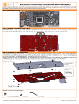
STEP 1: GENERAL INFORMATION. Sample picture of RADEON HD 6970 V2 graphic card
STEP 2: PREPARING YOUR GRAPHIC CARD.
1. REMOVING STOCK COOLER: Remove encircled
screws:
STEP 2 cont.: PREPARING YOUR GRAPHIC CARD.
1 cont.. REMOVING STOCK COOLER. Remove all encircled screws. All heat sink
assembly screws should be removed. There are up to 15 screws on the back of the
graphic card.
2. CLEANING THE PCB. Carefully detach the original heat sink after removing all
fasteners securing it to the board and bracket. Wipe off the remains (by using non–
abrasive cloth or Q-tip, as shown on sample photo) of the original thermal
compound until the components and circuit board are completely clean. EKWB does
not recommend using any liquids for removing paste.
3. APPLYING THERMAL COMPOUND
Apply thermal compound: lightly coat the GPU with for example Arctic Cooling MX2 ™ or
MX3 ™ thermal compound. Follow this link:
http://www.arctic-cooling.com/catalog/images/install_mx2_retail.pdf for detailed
instructions. EKWB recommends to apply thermal grease in cross form for best
performance (see sample picture).
4. CUTTING THERMAL PADS. Your block comes with thermal pads, which have to be
placed on chips (PLEASE REMOVE FOIL ON BOTH SIDES OF THERMAL PADS PRIOR
TO INSTALLATION. WARNING: DIMENSION BELLOW ARE SCALED.)
5. PLACING THERMAL PADS ON PCB. Place thermal pads on chips so that
numbers on chips match size of thermal pads. Thermal pad number 1, 2 and 3
will have to be cut by user to match all small power regulation chips (EKWB made
sure users have more than enough pads to cover all surfaces that need to be
covered to make block fully function). You can also use small drop of thermal
grease on chips to make thermal pads more adhesive.
6. PLACING STANDOFFS ON BLOCK. Standoffs are obligatory to make this
block fully functional. Please use small amount of thermal grease on
standoffs and glue them so they are concentric with mounting holes. Once
they are stuck to block be careful not to move them.
3
1
3
Thickness 0.5mm
Thickness 1.5mm
Thickness 1mm
2
1
We highly recommend using
small droplets of electrically
non-conductive thermal grease
over each phase regulator!
Placing the standoffs:
PCB number and equivalent:
AMD 109-D20431-00A
1
1
1
1
1
1
1
2
1

All disclosures, notices and warranty conditions are being written on the back of the box. Released on 20th of December, 2010.
7. PLACING BLOCK TO GRAPHIC CARD. During this process please make sure you align
holes on PCB with holes on block. Also pay attention not to use too much force by
pressing block down to PCB. Chips are prone to cracking.
8. ATTACHING BLOCK TO GRAPHIC CARD. By using Philips screwdriver screw in ten
enclosed M3x8 screws. EKWB recommends start screwing the screws around the
GPU core and continue outwards.
STEP 3: CHECKING FOR CONTACTS
Temporarily r
emove the water blocks to check for uniform surface contact between the block and the components. Note the pattern of contact on a piece of paper. Then repeat
steps 5 and 8 to reattach the block applying more or less pressure to the areas where you have found it necessary.
STEP 4: POSITIONING FITTINGS
Please use spacer on copper base (see sample picture). Screw in the fittings and plugs (please use spacers only on copper base), attach the liquid cooling tubes and connect the
water-block(s) into the cooling circuit. EKWB recommends using high flow fittings with the EK-FC 6970 V2 series water blocks. To ensure that the tubes are securely attached to
the barb/fittings, please use hose clamps or an appropriate substitute. The use of an algaecide is always recommended for any liquid cooling system.
You can use any opening as an inlet/outlet port.
STEP 5: INSERTING CARD IN YOUR PC CASE
Carefully lift your card with installed block and insert it in your PC case. Bear in mind that your card suddenly withstands extra weight thus again be very careful not to bend it or
cause any other unneeded moves that might damage your card or block during installation.
REQUIRED TOOLS AND MOUNTING SCREWS:
scissors philips screwdriver 10 x screws M3x8 DIN7985 10 x M3 PVC washers
Fittings
Gasket/O-ring
Spacer
Plug
6mm Allen key

All disclosures, notices and warranty conditions are being written on the back of the box and our web site. Released on 26th of January, 2011.
Installation and mounting manual for installing ɸ3mm LED
diodes in EK-FC 6970 V2 water block*
This product is intended for installation only by expert users. Please consult with a qualified technician for installation. Improper installation may result in damage to your equipment. EK Water Blocks assumes no liability
whatsoever, expressed or implied, for the use of these products, nor their installation. The following instructions are subject to change without notice. Please visit our web site at www.ekwaterblocks.com for updates.
Before installation of this product please read important notice, disclosure and warranty conditions printed on the back of the box.
IMPORTANT NOTICE: PLEASE NOTE THAT BY INSTALLING THE LED DIODES AND SUBSEQUENTLY REMOVING THE METAL LID WE CANNOT GUARANTEE THE WATER BLOCK AS FACTORY TESTED
LEAK-FREE!
* Only applies to EK-FC6970 V2 Nickel & EK-FC6970 V2 White Acetal
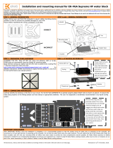
STEP 5: DISASSEMBLING THE WATER BLOCK
Please remove the EK-FC6970 V2 water block from your graphics card in
case you have already installed it. Drain the coolant in case the block was
already operational.
Remove all M3x6 and M3x12 screws securing the metal plate to the acrylic /
POM top. There is eleven (11) screw to remove all together. Make sure they
don’t get lost!
STEP 6: INSERTING THE ɸ3mm LED DIODES
Slide the ɸ3mm LED diodes through the opening (one by one). We
recommend using two LED diodes on a single cable:
STEP 6. Cont.: Align the cables into the pre-milled grooves.
STEP 7: RE-ASSEMBLE THE WATERBLOCK
Place the metal lid back on top of the water block. It is crucial that the rubber seal O-ring is positioned and aligned perfectly into it’s groove. Screw back all
M3x6 and M3x12 screws which are securing the metal plate to the acrylic / POM top. There is eleven (11) screw to screw in all together. Be especially careful
when screwing the M3x6 screws into the acrylic / POM top and use appropriate amount of force. Excessive force will strip the threads rendering the
block useless!
REQUIRED TOOLS AND MOUNTING SCREWS:
allen key 2.5mm
Make sure the O-ring is aligned
and sitting perfectly in the
milled groove.
Do not use excessive force
when screwing in the M3x6
screws attaching metal lid to
the acrylic / POM top!
/